EP0906997A1 - Verriegelungsvorrichtung mit einem nockenbetätigten Übertragungselement - Google Patents
Verriegelungsvorrichtung mit einem nockenbetätigten Übertragungselement Download PDFInfo
- Publication number
- EP0906997A1 EP0906997A1 EP98118362A EP98118362A EP0906997A1 EP 0906997 A1 EP0906997 A1 EP 0906997A1 EP 98118362 A EP98118362 A EP 98118362A EP 98118362 A EP98118362 A EP 98118362A EP 0906997 A1 EP0906997 A1 EP 0906997A1
- Authority
- EP
- European Patent Office
- Prior art keywords
- lever
- axis
- locking device
- cam
- active
- Prior art date
- Legal status (The legal status is an assumption and is not a legal conclusion. Google has not performed a legal analysis and makes no representation as to the accuracy of the status listed.)
- Withdrawn
Links
- 230000005540 biological transmission Effects 0.000 title claims abstract description 19
- 238000006073 displacement reaction Methods 0.000 description 2
- 230000000295 complement effect Effects 0.000 description 1
- 230000006835 compression Effects 0.000 description 1
- 238000007906 compression Methods 0.000 description 1
- 210000000056 organ Anatomy 0.000 description 1
Images


Classifications
-
- E—FIXED CONSTRUCTIONS
- E05—LOCKS; KEYS; WINDOW OR DOOR FITTINGS; SAFES
- E05B—LOCKS; ACCESSORIES THEREFOR; HANDCUFFS
- E05B1/00—Knobs or handles for wings; Knobs, handles, or press buttons for locks or latches on wings
- E05B1/0038—Sliding handles, e.g. push buttons
-
- E—FIXED CONSTRUCTIONS
- E05—LOCKS; KEYS; WINDOW OR DOOR FITTINGS; SAFES
- E05B—LOCKS; ACCESSORIES THEREFOR; HANDCUFFS
- E05B81/00—Power-actuated vehicle locks
- E05B81/02—Power-actuated vehicle locks characterised by the type of actuators used
- E05B81/04—Electrical
- E05B81/06—Electrical using rotary motors
-
- E—FIXED CONSTRUCTIONS
- E05—LOCKS; KEYS; WINDOW OR DOOR FITTINGS; SAFES
- E05B—LOCKS; ACCESSORIES THEREFOR; HANDCUFFS
- E05B81/00—Power-actuated vehicle locks
- E05B81/12—Power-actuated vehicle locks characterised by the function or purpose of the powered actuators
- E05B81/16—Power-actuated vehicle locks characterised by the function or purpose of the powered actuators operating on locking elements for locking or unlocking action
-
- E—FIXED CONSTRUCTIONS
- E05—LOCKS; KEYS; WINDOW OR DOOR FITTINGS; SAFES
- E05B—LOCKS; ACCESSORIES THEREFOR; HANDCUFFS
- E05B81/00—Power-actuated vehicle locks
- E05B81/24—Power-actuated vehicle locks characterised by constructional features of the actuator or the power transmission
- E05B81/32—Details of the actuator transmission
- E05B81/42—Cams
- E05B81/44—Cams in the form of grooves
-
- E—FIXED CONSTRUCTIONS
- E05—LOCKS; KEYS; WINDOW OR DOOR FITTINGS; SAFES
- E05B—LOCKS; ACCESSORIES THEREFOR; HANDCUFFS
- E05B15/00—Other details of locks; Parts for engagement by bolts of fastening devices
- E05B15/0053—Other details of locks; Parts for engagement by bolts of fastening devices means providing a stable, i.e. indexed, position of lock parts
-
- E—FIXED CONSTRUCTIONS
- E05—LOCKS; KEYS; WINDOW OR DOOR FITTINGS; SAFES
- E05B—LOCKS; ACCESSORIES THEREFOR; HANDCUFFS
- E05B17/00—Accessories in connection with locks
- E05B17/0054—Fraction or shear lines; Slip-clutches, resilient parts or the like for preventing damage when forced or slammed
-
- E—FIXED CONSTRUCTIONS
- E05—LOCKS; KEYS; WINDOW OR DOOR FITTINGS; SAFES
- E05B—LOCKS; ACCESSORIES THEREFOR; HANDCUFFS
- E05B83/00—Vehicle locks specially adapted for particular types of wing or vehicle
- E05B83/36—Locks for passenger or like doors
Definitions
- the invention relates to a locking device for a motor vehicle opening comprising a finger disengageable sliding transmission controlled by a cam.
- the invention relates more particularly to a locking device for a vehicle window automobile, of the type comprising an operating member for cause the opening of a door lock by through a linkage, and the type in which the linkage has a movable transmission finger, which is controlled between an active position, in which it cooperates with the operating member to cause the unlocking of the lock, and a disengaged position in which it is no longer likely to cooperate with the operating member so as to render the latter inoperative.
- the linkage which connects the operating member to the lock which, in turn, ensures maintaining the opening in the closed position, comprises usually rods and cross references.
- Such a device is to interpose in the linkage a movable element which, in an active position, allows the movement of the operating member to be transmitted to rest of the linkage to allow the operating member to order the lock. On the contrary, in a disengaged position of the transmission finger, the operating member can no longer act on the linkage and can therefore no longer order opening the lock.
- the object of the invention is to propose a new design of such a locking device in which the transmission finger can be controlled particularly simple and reliable between its active and disengaged.
- the invention provides a device for lock for a motor vehicle opening, of the type comprising an operating member to cause opening a lock of the sash via a linkage, and the type in which the linkage has a finger mobile transmission, which is controlled between an active position, in which it cooperates with the operating member for cause the lock to unlock, and a position disengaged in which he is no longer likely to cooperate with the operating member so as to make the latter inoperative, the finger being secured to a lever which is mounted pivoting on a fixed frame so as to pivot from a position rest at an open position around its axis of pivoting when, the finger being in the active position, the organ maneuvering causes the lock to open, and the lever being moved in sliding according to the direction of its axis of pivoting between an active position and a disengaged position to ensure the movement of the transmission finger between its corresponding active and disengaged positions, the lever has a cylindrical rod which extends along the pivot axis of the lever and which is guided, pivoting and sliding according to this axis
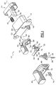
- the locking device 10 which is shown has a main housing 12, which forms a fixed frame, by example secured to the opening, and in which a pusher 14 is slidably mounted in a longitudinal direction of axis A1.
- the pusher 14 is movable longitudinally between a retracted position of rest, to which it is brought back by a compression spring 16 interposed between the pusher 14 and the case 12, and an advanced opening position in which it causes the opening of a door lock (not shown).
- the pusher 14 comprises a rod thrust 18 which extends longitudinally forward according to axis A1 through a window 20 arranged in a wall transverse front 22 of the housing 12 which forms the bottom of this case 12.
- the locking rod thrust 18 of pusher 14 is intended to cooperate with a linkage 24, which is arranged in front of the main housing 12, and which includes in particular an articulated reference 26 and a rod 28.
- the reference 26 is articulated on the housing 12, in front of the front transverse wall 22, around a transverse axis A2 perpendicular to the axis A1 and substantially horizontal such that shown in the figures.
- the reference 26 transforms a movement longitudinal axis A1 of pusher 14 in a movement of translation of the rod 28 in a perpendicular direction to axes A1 and A2.
- the rod thrust 18 does not act directly on the linkage 24 but via a transmission finger 30 which is worn by a lever 32.
- the lever 32 comprises a cylindrical rod 34 of axis A2, which is here substantially coincident with the axis of articulation of the reference 26, the rod 34 ensuring the pivoting mounting of the lever relative to the housing 12 of the device 10.
- the finger transmission 30 is in the form of a cylinder tubular with axis parallel to axis A2, but offset from the axis A2 of the rod 34 at one end of which it is connected by an arm 31 of radial orientation relative to the axis A2.
- the lever 32 is capable of sliding axially in the direction longitudinal of the axis A2 of its rod 34.
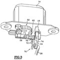
- the lever 34 is first of all capable of occupying a active axial position which is illustrated in FIGS. 2 and 3.
- the finger transmission 30 is arranged substantially along the longitudinal axis A1 of the push rod 18 of the pusher 14 and it is then arranged between a front end 36 of the push rod 18 and a bearing surface 38 of the articulated gear 26 so that, when the pusher 14 is advanced from its rest position, illustrated in FIG. 2, in its open position, illustrated in Figure 3, the push rod 18 causes the pivoting of the lever 32 from an angular position of rest to a position angular opening, the transmission finger 30 causing itself, bearing against the bearing surface 38, the pivoting of the reference 26 around the axis A2.
- the reference 26 causes the displacement of the rod 28 which, in turn, controls the opening of the lock.
- Elastic return means not shown allow to bring all the linkage 24 and the lever 32 towards their rest position when the pusher 14 is released and regains its rest position under the action spring 16.
- the lever 32 is capable of being moved axially towards a disengaged position, in the direction of the axis A2, i.e. in a direction perpendicular to the general plane of movements of the parts of the linkage 24 and of the pusher 14 between their rest position and their open position.
- the rod 34 of the lever 32 which is guided in rotation relative to the housing 12, is also guided in translation along its axis A2.
- the lever 32 is slidably controlled between its active and disengaged positions by a cam device.
- the device 10 comprises a wheel 52 which is rotatably mounted against the transverse front face 22 of the case 12 around an axis A4 parallel to the axis A1.
- the wheel 52 is thus arranged longitudinally along the axis A1 between the face front 22 of the housing 12 and the lever 32.
- the wheel 52 has a groove 56 arranged in a spiral around the axis A4.
- the groove 56 has a first end 58 which is radially more eccentric from the A4 axis than a second end 60 radially more inside.
- the groove 56 is intended for form a cam path for a cam follower 62 which is carried by the rod 34 of the lever 32 and which extends along an axis parallel to axis A4 when lever 32 is in position angular rest. In this position, the cam follower 62 is received inside the cam path formed by the groove 56.
- the wheel 52 forming a cam, is a toothed wheel which is likely to be rotated around its axis A4 by an electric motor 44, the motor shaft of the latter being provided with a control pinion 42 which cooperates with a surface external toothed side 64 of wheel 52.
- the motor 44 is intended to be received in a casing 46 which is fitted against the transverse front face 22 of the housing main 12 and which also ensures the rotation guidance of the toothed wheel 52 forming a cam and the guide in pivoting and in sliding of the lever 32 whose rod 34 is received in a cylindrical housing with axis A2 of the casing 46.
- Cam follower 62 extends perpendicularly from a plate element 66 of the lever 32 which extends to it radially with respect to the axis A2 of the rod 34. This element of plate 66 is intended to cooperate, when the lever 32 is in disengaged position, with a complementary stop surface 68 of the casing 46 to immobilize the lever 32 in an angular position rest, as illustrated in Figure 12.
- bistable return means which force lever 32 towards one or towards the other of its active or disengaged axial positions.
- the bistable return means consist of a pin 70 bent into two branches 72.
- the two branches 72 extend backwards substantially in the longitudinal direction of axis A1 and their free ends are mounted free in rotation about their axis respectively in housings 74, 76 of lever 32 and housing 46.
- the pin 70 not only ensures the bistable return of the lever 32 according to the axial direction but also its angular recall towards its rest position.
- the lever 32 includes a breakable pin 50 which extends axially from the transmission finger 30, in front of the window 20 of the housing body 12 when the lever 32 is in the disengaged position.
- the pawn 50 is capable of cooperating with the pusher 14 to prevent it to be brought to its open position. Indeed, the lever 32 is then immobilized in the angular position of rest.
- the pusher 14 can then be brought to its position longitudinal opening but, the transmission finger being in the disengaged position, and the pusher 14 cannot cooperate with the articulated return 26 nor with the rest of the linkage 24, pusher 14 is rendered inoperative in the sense that it can no longer order the opening of the lock.
Landscapes
- Lock And Its Accessories (AREA)
Applications Claiming Priority (2)
| Application Number | Priority Date | Filing Date | Title |
|---|---|---|---|
| FR9712192A FR2769037B1 (fr) | 1997-10-01 | 1997-10-01 | Dispositif de verrouillage comportant un doigt de transmission commande par came |
| FR9712192 | 1997-10-01 |
Publications (1)
| Publication Number | Publication Date |
|---|---|
| EP0906997A1 true EP0906997A1 (de) | 1999-04-07 |
Family
ID=9511667
Family Applications (1)
| Application Number | Title | Priority Date | Filing Date |
|---|---|---|---|
| EP98118362A Withdrawn EP0906997A1 (de) | 1997-10-01 | 1998-09-29 | Verriegelungsvorrichtung mit einem nockenbetätigten Übertragungselement |
Country Status (2)
| Country | Link |
|---|---|
| EP (1) | EP0906997A1 (de) |
| FR (1) | FR2769037B1 (de) |
Cited By (6)
| Publication number | Priority date | Publication date | Assignee | Title |
|---|---|---|---|---|
| FR2798156A1 (fr) * | 1999-09-03 | 2001-03-09 | Valeo Securite Habitacle | Dispositif de verrouillage d'un ouvrant de vehicule automobile comportant des moyens motorises de blocage de la tringlerie |
| US6938507B2 (en) | 2000-11-29 | 2005-09-06 | Meritor Light Vechicle Systems (Uk) Limited | Actuator |
| WO2007025644A1 (de) * | 2005-08-30 | 2007-03-08 | D. la Porte Söhne GmbH | Betätigungsvorrichtung für ein schloss |
| EP1568832A3 (de) * | 2004-02-26 | 2007-06-06 | D. La Porte Söhne Gmbh | Betätigungsvorrichtung für ein schloss |
| ITMC20080176A1 (it) * | 2008-09-30 | 2010-04-01 | So Ge Mi Spa | Dispositivo per la chiusura automatica della serratura di un portello di un veicolo. |
| CN111803164A (zh) * | 2020-08-27 | 2020-10-23 | 武汉智瓴医疗科技有限公司 | 用于击发吻合器的电动推击装置及电动吻合器 |
Families Citing this family (2)
| Publication number | Priority date | Publication date | Assignee | Title |
|---|---|---|---|---|
| FR2798950B1 (fr) | 1999-09-29 | 2002-05-10 | Valeo Securite Habitacle | Dispositif de verrouillage comportant un doigt de transmission debrayable commande par came |
| DE10322387A1 (de) * | 2003-05-17 | 2004-12-02 | Huf Hülsbeck & Fürst Gmbh & Co. Kg | Schließeinrichtung für Türen oder Klappen von Fahrzeugen |
Citations (6)
| Publication number | Priority date | Publication date | Assignee | Title |
|---|---|---|---|---|
| GB930060A (en) * | 1961-07-17 | 1963-07-03 | Ford Motor Co | Improved door latch mechanism actuating device |
| FR2303929A1 (fr) * | 1975-03-14 | 1976-10-08 | Peugeot & Renault | Dispositif de condamnation d'une porte de coffre arriere d'un vehicule par debrayage de la commande d'ouverture |
| DE3500550A1 (de) * | 1985-01-10 | 1985-10-31 | Daimler-Benz Ag, 7000 Stuttgart | Schlosssystem in einem kraftfahrzeug-tuerverschluss |
| EP0589158A1 (de) * | 1992-08-25 | 1994-03-30 | Bayerische Motoren Werke Aktiengesellschaft | Fernsteuerbares Schloss, insbesondere für Kraftfahrzeugtüren |
| DE19541396A1 (de) * | 1995-11-07 | 1997-05-15 | Ymos Ag Ind Produkte | Kraftfahrzeug-Türgriff |
| EP0791708A2 (de) * | 1996-02-26 | 1997-08-27 | Valeo Securite Habitacle | Verriegelungsvorrichtung eines Fahrzeugsflügels mit Mitteln zur Blockierung der Betätigungsgestange |
-
1997
- 1997-10-01 FR FR9712192A patent/FR2769037B1/fr not_active Expired - Fee Related
-
1998
- 1998-09-29 EP EP98118362A patent/EP0906997A1/de not_active Withdrawn
Patent Citations (6)
| Publication number | Priority date | Publication date | Assignee | Title |
|---|---|---|---|---|
| GB930060A (en) * | 1961-07-17 | 1963-07-03 | Ford Motor Co | Improved door latch mechanism actuating device |
| FR2303929A1 (fr) * | 1975-03-14 | 1976-10-08 | Peugeot & Renault | Dispositif de condamnation d'une porte de coffre arriere d'un vehicule par debrayage de la commande d'ouverture |
| DE3500550A1 (de) * | 1985-01-10 | 1985-10-31 | Daimler-Benz Ag, 7000 Stuttgart | Schlosssystem in einem kraftfahrzeug-tuerverschluss |
| EP0589158A1 (de) * | 1992-08-25 | 1994-03-30 | Bayerische Motoren Werke Aktiengesellschaft | Fernsteuerbares Schloss, insbesondere für Kraftfahrzeugtüren |
| DE19541396A1 (de) * | 1995-11-07 | 1997-05-15 | Ymos Ag Ind Produkte | Kraftfahrzeug-Türgriff |
| EP0791708A2 (de) * | 1996-02-26 | 1997-08-27 | Valeo Securite Habitacle | Verriegelungsvorrichtung eines Fahrzeugsflügels mit Mitteln zur Blockierung der Betätigungsgestange |
Cited By (8)
| Publication number | Priority date | Publication date | Assignee | Title |
|---|---|---|---|---|
| FR2798156A1 (fr) * | 1999-09-03 | 2001-03-09 | Valeo Securite Habitacle | Dispositif de verrouillage d'un ouvrant de vehicule automobile comportant des moyens motorises de blocage de la tringlerie |
| US6938507B2 (en) | 2000-11-29 | 2005-09-06 | Meritor Light Vechicle Systems (Uk) Limited | Actuator |
| EP1568832A3 (de) * | 2004-02-26 | 2007-06-06 | D. La Porte Söhne Gmbh | Betätigungsvorrichtung für ein schloss |
| WO2007025644A1 (de) * | 2005-08-30 | 2007-03-08 | D. la Porte Söhne GmbH | Betätigungsvorrichtung für ein schloss |
| ITMC20080176A1 (it) * | 2008-09-30 | 2010-04-01 | So Ge Mi Spa | Dispositivo per la chiusura automatica della serratura di un portello di un veicolo. |
| WO2010038249A1 (en) * | 2008-09-30 | 2010-04-08 | So.Ge.Mi.-S.P.A. | Automatic closing device of vehicle door locks |
| CN111803164A (zh) * | 2020-08-27 | 2020-10-23 | 武汉智瓴医疗科技有限公司 | 用于击发吻合器的电动推击装置及电动吻合器 |
| CN111803164B (zh) * | 2020-08-27 | 2023-11-10 | 武汉智瓴医疗科技有限公司 | 用于击发吻合器的电动推击装置及电动吻合器 |
Also Published As
| Publication number | Publication date |
|---|---|
| FR2769037B1 (fr) | 1999-11-19 |
| FR2769037A1 (fr) | 1999-04-02 |
Similar Documents
| Publication | Publication Date | Title |
|---|---|---|
| EP3581742B1 (de) | Flächenbündiger türgriff und verfahren zum betrieb davon | |
| EP3404177B1 (de) | Steuermechanismus eines flächenbündigen griffs | |
| EP3405633B1 (de) | Externe öffnungssteuerung eines kraftfahrzeugs | |
| EP3404176B1 (de) | Vorrichtung zum entriegeln eines türschlosses | |
| FR2503233A1 (fr) | Dispositif de reglage de position, notamment installation combinee de manoeuvre de vitre et de verrouillage central de porte de vehicule automobile | |
| EP0179002A1 (de) | Einrichtung zum automatischen Schliessen, sowie zum Offenhalten von Türen | |
| FR2787822A1 (fr) | Agencement de poignee pour une piece de carrosserie mobile d'un vehicule automobile | |
| FR2652318A1 (fr) | Retroviseur exterieur pour vehicule. | |
| FR2769037A1 (fr) | Dispositif de verrouillage comportant un doigt de transmission commande par came | |
| EP1201851B1 (de) | Türgriffanordnung für eine Schiebetür eines Kraftfahrzeuges | |
| EP1745186B1 (de) | Zurückziehbarer einsatzschlüssel mit einsatztreibmitteln | |
| EP3763903B1 (de) | Griff eines öffnungselements für kraftfahrzeug | |
| EP0243214B1 (de) | Verriegelungsvorrichtung verwendbar als Diebstahlsicherung für ein elektrisches Kraftfahrzeugtürschloss und übereinstimmendes Schloss | |
| EP0102263B1 (de) | Elektrisches Schloss für Kraftfahrzeugtür | |
| FR2769036A1 (fr) | Dispositif de verrouillage comportant un doigt de transmission commande par une cremaillere | |
| EP0940530A1 (de) | Verriegelungsvorrichtung für einen Kraftfahrzeugsflügel mit einem drehbaren Element, das mittels eines Nockens in eine nicht gekuppelte Position verschoben werden kann | |
| EP1458945B1 (de) | Elektrische verriegelung | |
| EP2069169A1 (de) | Wischermechanismus mit einem mittel zur verriegelung einer antriebswelle in einer winkelstellung | |
| EP4321713B1 (de) | Verriegelungsvorrichtung für eine klappe eines fahrzeugs | |
| FR2769038A1 (fr) | Dispositif de verrouillage comportant un doigt de transmission debrayable par basculement | |
| FR3107295A1 (fr) | Dispositif de verrouillage pour une pièce mobile d’un véhicule | |
| EP2503082B1 (de) | Motorised lock for automobile | |
| FR2474573A1 (fr) | Dispositif d'actionnement electrique pour un organe de manoeuvre de serrures et objets analogues | |
| EP1088954A1 (de) | Verriegelungsvorrichtung mit einem mittels eines Nockens ausschaltbaren Übertragungsfinger | |
| FR2927431A1 (fr) | Dispositif de commande en ouverture d'un ouvrant de vehicule automobile. |
Legal Events
| Date | Code | Title | Description |
|---|---|---|---|
| PUAI | Public reference made under article 153(3) epc to a published international application that has entered the european phase |
Free format text: ORIGINAL CODE: 0009012 |
|
| AK | Designated contracting states |
Kind code of ref document: A1 Designated state(s): AT BE CH CY DE DK ES FI FR GB GR IE IT LI LU MC NL PT SE |
|
| AX | Request for extension of the european patent |
Free format text: AL;LT;LV;MK;RO;SI |
|
| AKX | Designation fees paid | ||
| REG | Reference to a national code |
Ref country code: DE Ref legal event code: 8566 |
|
| STAA | Information on the status of an ep patent application or granted ep patent |
Free format text: STATUS: THE APPLICATION IS DEEMED TO BE WITHDRAWN |
|
| 18D | Application deemed to be withdrawn |
Effective date: 19991008 |