EP0046317B1 - Procédé et dispositif pour détecter la direction d'un court-circuit - Google Patents
Procédé et dispositif pour détecter la direction d'un court-circuit Download PDFInfo
- Publication number
- EP0046317B1 EP0046317B1 EP19810200845 EP81200845A EP0046317B1 EP 0046317 B1 EP0046317 B1 EP 0046317B1 EP 19810200845 EP19810200845 EP 19810200845 EP 81200845 A EP81200845 A EP 81200845A EP 0046317 B1 EP0046317 B1 EP 0046317B1
- Authority
- EP
- European Patent Office
- Prior art keywords
- current
- signal
- voltage
- difference
- signals
- Prior art date
- Legal status (The legal status is an assumption and is not a legal conclusion. Google has not performed a legal analysis and makes no representation as to the accuracy of the status listed.)
- Expired
Links
- 238000000034 method Methods 0.000 title claims description 10
- 230000008569 process Effects 0.000 title description 2
- 238000005259 measurement Methods 0.000 claims description 36
- 230000006870 function Effects 0.000 claims description 6
- 238000001514 detection method Methods 0.000 description 17
- 238000011156 evaluation Methods 0.000 description 8
- 230000005284 excitation Effects 0.000 description 7
- 230000010355 oscillation Effects 0.000 description 6
- 230000015572 biosynthetic process Effects 0.000 description 5
- 230000008859 change Effects 0.000 description 5
- 230000008901 benefit Effects 0.000 description 3
- 238000010586 diagram Methods 0.000 description 3
- 230000000903 blocking effect Effects 0.000 description 2
- 230000001419 dependent effect Effects 0.000 description 2
- 238000012986 modification Methods 0.000 description 2
- 230000004048 modification Effects 0.000 description 2
- 238000012544 monitoring process Methods 0.000 description 2
- 238000005070 sampling Methods 0.000 description 2
- 230000001960 triggered effect Effects 0.000 description 2
- 230000006978 adaptation Effects 0.000 description 1
- 230000003111 delayed effect Effects 0.000 description 1
- 238000011161 development Methods 0.000 description 1
- 230000005611 electricity Effects 0.000 description 1
- 238000012545 processing Methods 0.000 description 1
- 230000001681 protective effect Effects 0.000 description 1
- 230000004044 response Effects 0.000 description 1
- 230000009131 signaling function Effects 0.000 description 1
Images

Classifications
-
- G—PHYSICS
- G01—MEASURING; TESTING
- G01R—MEASURING ELECTRIC VARIABLES; MEASURING MAGNETIC VARIABLES
- G01R31/00—Arrangements for testing electric properties; Arrangements for locating electric faults; Arrangements for electrical testing characterised by what is being tested not provided for elsewhere
- G01R31/08—Locating faults in cables, transmission lines, or networks
-
- H—ELECTRICITY
- H02—GENERATION; CONVERSION OR DISTRIBUTION OF ELECTRIC POWER
- H02H—EMERGENCY PROTECTIVE CIRCUIT ARRANGEMENTS
- H02H3/00—Emergency protective circuit arrangements for automatic disconnection directly responsive to an undesired change from normal electric working condition with or without subsequent reconnection ; integrated protection
- H02H3/38—Emergency protective circuit arrangements for automatic disconnection directly responsive to an undesired change from normal electric working condition with or without subsequent reconnection ; integrated protection responsive to both voltage and current; responsive to phase angle between voltage and current
- H02H3/382—Emergency protective circuit arrangements for automatic disconnection directly responsive to an undesired change from normal electric working condition with or without subsequent reconnection ; integrated protection responsive to both voltage and current; responsive to phase angle between voltage and current involving phase comparison between current and voltage or between values derived from current and voltage
Definitions
- the invention relates to methods and a device for short-circuit direction detection on electrical devices, in particular electrical lines and power supply networks, according to the preambles of claims 1, 2 and 3.
- the invention relates to a prior art of methods and devices for short-circuit direction detection, as described in FR-A-2 380 631.
- a phase direction comparison of current and voltage difference signals which are derived from power supply lines to be monitored, generates an error direction criterion with respect to the measurement location.
- These difference signals are by means of memory elements, for. B. in terms of amplitude and phase tuned oscillators, which are controlled by the output signal of an error detector (impedance relay). This error detector output signal also causes the error direction signal to be released. Storage in the memory elements only begins after a period of time ⁇ T 2 after the error has occurred, ie after the error detector has responded. After that, a time period ⁇ T 1 passes again until an error direction signal is available.
- the object of the invention is to shorten the time for a short-circuit direction detection and at the same time to ensure a high reliability of the detection.
- One advantage of the invention is that the evaluable signs of the differential signals are available comparatively quickly and thus enable protective devices or current cutoffs of the lines affected by the short circuit to be triggered quickly and selectively.
- a voltage reference signal is derived from the time profile of the voltage signal by a predefinable time delay, which is an integral multiple of the basic period.
- phase angle comparison of current and voltage signals are known from the book by Leonhard Müller, Selective Protection of Electrical Systems, 1971, Publishing and Business Corporation of Elektrizticianstechnike mbH., Frankfurt / Main, p. 58 ff. These known methods essentially work with the fundamental oscillation of electricity - and voltage and therefore require extensive filters for both the current and voltage measurement channels with regard to the compensation processes in the event of a short circuit.
- a reliable sign or phase angle evaluation of the current and voltage signals for ⁇ fault direction detection is therefore only possible after the filter has settled with a corresponding delay.
- the phase angle evaluation also limits - for example by evaluating voltage zero crossings - the response time of a short-circuit direction detector down to at least one half period of the basic oscillation.
- a measuring point 2 with a current transformer 3 and a voltage transformer 4 is provided in a power supply line 1 to be monitored for a short circuit.
- K denotes a short-circuit point in a predeterminable forward direction V of the power supply line 1.
- the current measurement signal i derived from the current transformer 3 and proportional to the current in the power supply line 1 becomes a current measurement channel with two subchannels 1 1 and 1 2 for the two opposite sign oscillations fed.
- the voltage measurement signal u derived from the voltage converter 4 and proportional to the voltage in the power supply line 1 is fed to a voltage measurement channel U.
- a difference signal generator DI 1 or DI 2 is arranged, which on the one hand and the current measurement signals i 1 and i 2 on the other hand, based on the relevant half-oscillation of the current measurement signal i, Limit or to a current reference signal + i o or - i o are limited, forms a current difference signal ⁇ i 1 and ⁇ i 2 .
- These two current difference signals .DELTA.i 1 and .DELTA.i 2 assigned to the half oscillations of the current are applied to a sign detector of a conventional type, e.g. B.
- the current limit values for the current measurement signals i 1 or i 2 are shown in the sub-channels 1 1 and 1 2 are formed by means of reference signal transmitters GI 1 and GI 2 , which are designed as measurement limiters. The following applies to the current measurement signal i 1 from GI 1 :
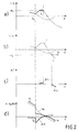
- the output signal of the difference signal formers DI 1 (FIG. 2a) or D1 2 (FIG. 2b) remains zero as long as + i o or - i o is not exceeded or undershot by i.
- the amount of the current limit value i o thus represents a limit value which corresponds to an overcurrent excitation criterion.
- FIG. 2c shows the current difference signals ⁇ i 1 and ⁇ i 2 corresponding to the limit violations in FIGS. 2a and 2b.
- 2d shows corresponding signals for the voltage in the event of a short circuit in the short circuit point K at time t0 in the forward direction V with respect to the measuring point.
- i o is then not a constant but a function of the current measurement signal i o .
- a current limit value i o is obtained shortly before an error occurs, depending on an error excitation signal, e.g. B. depending on a limit violation of a current rise or a di / dt signal.
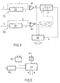
- the excitation channel is designated by A in FIG.
- a release criterion for the direction detection in the form of a limit value monitoring of ⁇ i 1 and ⁇ i 2 can be provided by means of corresponding limit switches GS 1 and GS 2 and a downstream OR gate GO for the release or blocking of a sign comparison circuit CS .
- These limit switches deliver z. B. only then an output signal via line 9 when predetermined limit values are exceeded.
- the sign comparison circuit points. e.g. B. a known and therefore not shown equivalence in series with a release switch. This enables closer error selection to be achieved.
- t is the time and ⁇ is a predeterminable delay period of z. B. 4 ms, preferably less than half a period of the network frequency.
- the output signal of the difference signal generator DU arrives via a sign detector in the form of a trigger TR u , z. B. a circuit for realizing the signal function, together with the corresponding binary signal from the trigger TR i to the sign comparison circuit CS.
- a signal e.g. B. at the output 5 of the sign comparison circuit CS with a different sign of the signals ⁇ i and Au corresponds to a short circuit in the forward direction V with respect to the measuring point 2 in accordance with the indicated arrow directions of i and u.
- a signal at the output 6 of the sign comparison circuit CS with the same sign of Ai and Au corresponds to a short circuit in the reverse direction, ie a short circuit in the opposite direction from V.
- a reversal of the current and voltage direction at the current transformer 3 and voltage transformer 4 has no influence on the output signals at the Outputs 5 and 6. If only one of these two values is reversed, the outputs of the sign comparison circuit CS must also be interchanged.
- a simple current measuring channel I with a reference signal generator GI in the form of a delay circuit ZI is provided as a dynamic memory circuit.
- the undelayed current measurement signal i and the current measurement signal delayed in ZI are fed as the current reference signal i o to the subsequent difference signal generator DI.
- the delay time of ZI can be comparatively short, preferably less than a fundamental half-period, for example less than 3 ms, since it is essentially only a question of generating a difference signal which indicates the respective change direction of the current with its sign, namely in as short as possible after the error occurs.
- the lower limit of the delay time is practically only determined by the interference level of the current measurement signal, which should not impair reliable sign detection.
- This version is also suitable for continuous monitoring of the measurement signals if necessary, independently of a separate fault excitation, with the relevant sign information of the current or the current change occurring continuously.
- the current delay mentioned in the formation of i o does not represent a detection delay because a short-circuit-related, e.g. B. sudden change in current immediately enters the current difference signal and determines its sign.
- the voltage reference signal u o can basically be formed in the same way as in the circuit according to FIG. 1 by means of a delay.
- an oscillator SU which is matched to the fundamental oscillation and is coupled on the input side for synchronization with the voltage measurement signal is provided for the voltage reference signal transmitter GU s .
- the voltage reference signal u o thus represents a continuation of the undisturbed voltage beyond the occurrence of the fault.
- the generally sudden voltage change in the event of a short circuit accordingly immediately generates a comparatively large difference signal.
- the difference signal formation gives the advantage of high signal dynamics in comparison with a detection in which signal amplitudes are used.
- the formation of the voltage reference signal using an oscillator has the particular advantage that the reference voltage, in contrast to the mere delay of the voltage measurement signal, is available for repeated direction detection even after a basic oscillation period has elapsed.
- the evaluation is again carried out in a sign comparison circuit CS.
- a separate release of the evaluation circuit as a function of the magnitude of the current difference signal is provided, specifically in the form of a magnitude comparison with predeterminable low, generally zero-point symmetrical current limit values G 1 and G 2 .
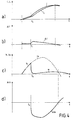
- the sign evaluation is only released if the amount ⁇ i exceeds predetermined values. This avoids uncertainties in the direction detection of short circuits when ⁇ i goes through 0, cf. 4a and b.
- the release can be blocked for smaller, interference-sensitive amounts of the voltage difference signal ⁇ u by increasing the amounts of the current limit values G 1 and G 2 .
- this limit value setting enables a particularly reliable release criterion for direction detection.
- FIGS. 4a-4d are shown for a short circuit in the forward direction V at time t at the short circuit point K in FIGS. 4a-4d, specifically for i, u, i o , u o and the corresponding ones Difference signals ⁇ i and ⁇ u.
- the evaluation of the difference signals ⁇ i and ⁇ u and thus the error direction detection can be triggered or released with a certain time delay above the error occurrence detected by a special excitation.
- the sign comparison circuit CS is connected to the trigger channel A with a corresponding blocking and release input via a timing element Z.
- the remaining circuit which can overlap with the embodiment according to FIG. 1 or FIG. 3, only the triggers TR and TR u are indicated for the sign detection of the difference signals.
- a single-channel limiter for ⁇ i 0 could be used instead of the two subchannels of the current measuring channel.
- the triggers TR i TR u with binary output signals
- circuits with 3 output states e.g. B. «- 1», «0», and «+ 1» can be used, whereby the 0 signal is present when the predefinable limit value for the current or the voltage has not been exceeded. Leaving state “0” corresponds to a release criterion for the emission of a short-circuit direction signal.
- the triggers TR i and TR u can be connected to the enable input of the sign comparison circuit CS via lines 7 and 8 shown in dashed lines and the enable line 9.
Landscapes
- Physics & Mathematics (AREA)
- General Physics & Mathematics (AREA)
- Locating Faults (AREA)
- Testing Of Short-Circuits, Discontinuities, Leakage, Or Incorrect Line Connections (AREA)
- Measurement Of Current Or Voltage (AREA)
Claims (4)
caractérisé en ce que
caractérisé en ce que
caractérisé en ce que
Applications Claiming Priority (2)
| Application Number | Priority Date | Filing Date | Title |
|---|---|---|---|
| CH616780 | 1980-08-15 | ||
| CH6167/80 | 1980-08-15 |
Publications (2)
| Publication Number | Publication Date |
|---|---|
| EP0046317A1 EP0046317A1 (fr) | 1982-02-24 |
| EP0046317B1 true EP0046317B1 (fr) | 1985-01-30 |
Family
ID=4305322
Family Applications (1)
| Application Number | Title | Priority Date | Filing Date |
|---|---|---|---|
| EP19810200845 Expired EP0046317B1 (fr) | 1980-08-15 | 1981-07-23 | Procédé et dispositif pour détecter la direction d'un court-circuit |
Country Status (3)
| Country | Link |
|---|---|
| EP (1) | EP0046317B1 (fr) |
| JP (1) | JPS5754873A (fr) |
| DE (1) | DE3168624D1 (fr) |
Families Citing this family (5)
| Publication number | Priority date | Publication date | Assignee | Title |
|---|---|---|---|---|
| EP0098624B1 (fr) * | 1982-06-23 | 1986-01-22 | BBC Aktiengesellschaft Brown, Boveri & Cie. | Procédé pour détecter des défauts ou la direction des défauts dans des lignes électriques et moyens pour sa mise en oeuvre |
| FR2538122A1 (fr) * | 1982-12-16 | 1984-06-22 | Enertec | Perfectionnement aux procedes et dispositifs de determination d'un parametre associe a une ligne electrique en defaut |
| JPH073450B2 (ja) * | 1984-02-22 | 1995-01-18 | 財団法人鉄道総合技術研究所 | 直流電鉄き電回路の故障点標定方法 |
| JPH0654339B2 (ja) * | 1985-07-04 | 1994-07-20 | 日立電線株式会社 | 故障方向標定方式 |
| CN111796164B (zh) * | 2020-07-16 | 2021-04-13 | 西南交通大学 | 一种全并联at牵引网故障测距方法 |
Family Cites Families (2)
| Publication number | Priority date | Publication date | Assignee | Title |
|---|---|---|---|---|
| FR2380631A1 (fr) * | 1977-02-09 | 1978-09-08 | Schlumberger Compteurs | Relais directionnel |
| US4187461A (en) * | 1978-02-21 | 1980-02-05 | Dranetz Engineering Laboratories, Inc. | Dynamic threshold impulse directivity indicator |
-
1981
- 1981-07-23 DE DE8181200845T patent/DE3168624D1/de not_active Expired
- 1981-07-23 EP EP19810200845 patent/EP0046317B1/fr not_active Expired
- 1981-08-13 JP JP12605881A patent/JPS5754873A/ja active Pending
Also Published As
| Publication number | Publication date |
|---|---|
| JPS5754873A (en) | 1982-04-01 |
| EP0046317A1 (fr) | 1982-02-24 |
| DE3168624D1 (en) | 1985-03-14 |
Similar Documents
| Publication | Publication Date | Title |
|---|---|---|
| DE69114732T2 (de) | Einrichtung zur Überwachung des Betriebs eines Mikroprozessorsystems oder dergleichen. | |
| EP0127139B1 (fr) | Circuit de contrôle d'une tension d'alimentation | |
| DE4419617C2 (de) | Anordnung zur Feststellung und/oder Überwachung eines vorbestimmten Füllstands in einem Behälter | |
| DE2523006C3 (de) | Verfahren und Einrichtung zur Fehlerortung auf einer Leitung | |
| DE2609654A1 (de) | Digitaler ueberstromausloeser | |
| DE2952156C2 (fr) | ||
| DE2338882A1 (de) | Verfahren und fernwirksystem zum einund ausschalten von elektrischen verbrauchern | |
| DE2545325B2 (de) | Schaltungsanordnung zur Messung des Isolationswiderstandes erdfreier Starkstromschaltungen | |
| EP0358887A2 (fr) | Circuit de détection d'erreur dans un appareil de mesure | |
| EP0046317A1 (fr) | Procédé et dispositif pour détecter la direction d'un court-circuit | |
| CH623963A5 (fr) | ||
| EP0098624A1 (fr) | Procédé pour détecter des défauts ou la direction des défauts dans des lignes électriques et moyens pour sa mise en oeuvre | |
| EP0741871A1 (fr) | Procede de mesure du courant passant dans le conducteur d'un reseau de transport de courant alternatif | |
| DE2939021C2 (de) | Verfahren zum digitalen Vervielfachen einer Signal-Frequenz | |
| DE3836811C2 (fr) | ||
| DE2144537C3 (de) | Meldeanlage | |
| DE2621071A1 (de) | Pendelschutzrelais | |
| EP0015226B1 (fr) | Circuit pour mémoriser la position de phase d'une tension alternative | |
| DE2554223C3 (de) | Steuereinrichtung zur Aufrechterhaltung der Stabilität eines Wechselrichters | |
| DE2316437A1 (de) | Geraet zum anzeigen der geschwindigkeit einer stroemungsmittelstroemung | |
| DE4430177A1 (de) | Überwachungsvorrichtung für einen Prozessor | |
| DE19738346C2 (de) | Signalüberwachungsschaltung | |
| DE3124073C2 (de) | Verfahren und Anordnung zur Durchführung des Verfahrens zur digitalen Überwachung von definierten Stromzuständen oder diesen proportionalen Spannungsabfällen | |
| EP0149097A2 (fr) | Procédé et dispositif pour l'évaluation sûre d'une alarme d'une ligne de signalisation d'un dispositif de signalisation de danger | |
| EP0050744B1 (fr) | Dispositif pour détecter le glissement de fréquence d'un circuit oscillateur |
Legal Events
| Date | Code | Title | Description |
|---|---|---|---|
| PUAI | Public reference made under article 153(3) epc to a published international application that has entered the european phase |
Free format text: ORIGINAL CODE: 0009012 |
|
| AK | Designated contracting states |
Designated state(s): CH DE SE |
|
| 17P | Request for examination filed |
Effective date: 19820319 |
|
| GRAA | (expected) grant |
Free format text: ORIGINAL CODE: 0009210 |
|
| AK | Designated contracting states |
Designated state(s): CH DE LI SE |
|
| REF | Corresponds to: |
Ref document number: 3168624 Country of ref document: DE Date of ref document: 19850314 |
|
| PLBE | No opposition filed within time limit |
Free format text: ORIGINAL CODE: 0009261 |
|
| STAA | Information on the status of an ep patent application or granted ep patent |
Free format text: STATUS: NO OPPOSITION FILED WITHIN TIME LIMIT |
|
| 26N | No opposition filed | ||
| PGFP | Annual fee paid to national office [announced via postgrant information from national office to epo] |
Ref country code: SE Payment date: 19890619 Year of fee payment: 9 |
|
| PGFP | Annual fee paid to national office [announced via postgrant information from national office to epo] |
Ref country code: DE Payment date: 19890925 Year of fee payment: 9 |
|
| PGFP | Annual fee paid to national office [announced via postgrant information from national office to epo] |
Ref country code: CH Payment date: 19891024 Year of fee payment: 9 |
|
| PG25 | Lapsed in a contracting state [announced via postgrant information from national office to epo] |
Ref country code: SE Effective date: 19900724 |
|
| PG25 | Lapsed in a contracting state [announced via postgrant information from national office to epo] |
Ref country code: LI Effective date: 19900731 Ref country code: CH Effective date: 19900731 |
|
| REG | Reference to a national code |
Ref country code: CH Ref legal event code: PL |
|
| PG25 | Lapsed in a contracting state [announced via postgrant information from national office to epo] |
Ref country code: DE Effective date: 19910403 |
|
| EUG | Se: european patent has lapsed |
Ref document number: 81200845.6 Effective date: 19910402 |