EP0046432A2 - Scheibenbremse - Google Patents
Scheibenbremse Download PDFInfo
- Publication number
- EP0046432A2 EP0046432A2 EP81401290A EP81401290A EP0046432A2 EP 0046432 A2 EP0046432 A2 EP 0046432A2 EP 81401290 A EP81401290 A EP 81401290A EP 81401290 A EP81401290 A EP 81401290A EP 0046432 A2 EP0046432 A2 EP 0046432A2
- Authority
- EP
- European Patent Office
- Prior art keywords
- pin assembly
- caliper
- sleeve
- opening
- bolt
- Prior art date
- Legal status (The legal status is an assumption and is not a legal conclusion. Google has not performed a legal analysis and makes no representation as to the accuracy of the status listed.)
- Withdrawn
Links
Images

Classifications
-
- F—MECHANICAL ENGINEERING; LIGHTING; HEATING; WEAPONS; BLASTING
- F16—ENGINEERING ELEMENTS AND UNITS; GENERAL MEASURES FOR PRODUCING AND MAINTAINING EFFECTIVE FUNCTIONING OF MACHINES OR INSTALLATIONS; THERMAL INSULATION IN GENERAL
- F16D—COUPLINGS FOR TRANSMITTING ROTATION; CLUTCHES; BRAKES
- F16D55/00—Brakes with substantially-radial braking surfaces pressed together in axial direction, e.g. disc brakes
- F16D55/02—Brakes with substantially-radial braking surfaces pressed together in axial direction, e.g. disc brakes with axially-movable discs or pads pressed against axially-located rotating members
- F16D55/22—Brakes with substantially-radial braking surfaces pressed together in axial direction, e.g. disc brakes with axially-movable discs or pads pressed against axially-located rotating members by clamping an axially-located rotating disc between movable braking members, e.g. movable brake discs or brake pads
- F16D55/224—Brakes with substantially-radial braking surfaces pressed together in axial direction, e.g. disc brakes with axially-movable discs or pads pressed against axially-located rotating members by clamping an axially-located rotating disc between movable braking members, e.g. movable brake discs or brake pads with a common actuating member for the braking members
- F16D55/225—Brakes with substantially-radial braking surfaces pressed together in axial direction, e.g. disc brakes with axially-movable discs or pads pressed against axially-located rotating members by clamping an axially-located rotating disc between movable braking members, e.g. movable brake discs or brake pads with a common actuating member for the braking members the braking members being brake pads
- F16D55/226—Brakes with substantially-radial braking surfaces pressed together in axial direction, e.g. disc brakes with axially-movable discs or pads pressed against axially-located rotating members by clamping an axially-located rotating disc between movable braking members, e.g. movable brake discs or brake pads with a common actuating member for the braking members the braking members being brake pads in which the common actuating member is moved axially, e.g. floating caliper disc brakes
- F16D55/2265—Brakes with substantially-radial braking surfaces pressed together in axial direction, e.g. disc brakes with axially-movable discs or pads pressed against axially-located rotating members by clamping an axially-located rotating disc between movable braking members, e.g. movable brake discs or brake pads with a common actuating member for the braking members the braking members being brake pads in which the common actuating member is moved axially, e.g. floating caliper disc brakes the axial movement being guided by one or more pins engaging bores in the brake support or the brake housing
- F16D55/227—Brakes with substantially-radial braking surfaces pressed together in axial direction, e.g. disc brakes with axially-movable discs or pads pressed against axially-located rotating members by clamping an axially-located rotating disc between movable braking members, e.g. movable brake discs or brake pads with a common actuating member for the braking members the braking members being brake pads in which the common actuating member is moved axially, e.g. floating caliper disc brakes the axial movement being guided by one or more pins engaging bores in the brake support or the brake housing by two or more pins
-
- F—MECHANICAL ENGINEERING; LIGHTING; HEATING; WEAPONS; BLASTING
- F16—ENGINEERING ELEMENTS AND UNITS; GENERAL MEASURES FOR PRODUCING AND MAINTAINING EFFECTIVE FUNCTIONING OF MACHINES OR INSTALLATIONS; THERMAL INSULATION IN GENERAL
- F16D—COUPLINGS FOR TRANSMITTING ROTATION; CLUTCHES; BRAKES
- F16D55/00—Brakes with substantially-radial braking surfaces pressed together in axial direction, e.g. disc brakes
- F16D55/02—Brakes with substantially-radial braking surfaces pressed together in axial direction, e.g. disc brakes with axially-movable discs or pads pressed against axially-located rotating members
- F16D55/22—Brakes with substantially-radial braking surfaces pressed together in axial direction, e.g. disc brakes with axially-movable discs or pads pressed against axially-located rotating members by clamping an axially-located rotating disc between movable braking members, e.g. movable brake discs or brake pads
- F16D55/224—Brakes with substantially-radial braking surfaces pressed together in axial direction, e.g. disc brakes with axially-movable discs or pads pressed against axially-located rotating members by clamping an axially-located rotating disc between movable braking members, e.g. movable brake discs or brake pads with a common actuating member for the braking members
- F16D55/225—Brakes with substantially-radial braking surfaces pressed together in axial direction, e.g. disc brakes with axially-movable discs or pads pressed against axially-located rotating members by clamping an axially-located rotating disc between movable braking members, e.g. movable brake discs or brake pads with a common actuating member for the braking members the braking members being brake pads
- F16D55/226—Brakes with substantially-radial braking surfaces pressed together in axial direction, e.g. disc brakes with axially-movable discs or pads pressed against axially-located rotating members by clamping an axially-located rotating disc between movable braking members, e.g. movable brake discs or brake pads with a common actuating member for the braking members the braking members being brake pads in which the common actuating member is moved axially, e.g. floating caliper disc brakes
- F16D55/2265—Brakes with substantially-radial braking surfaces pressed together in axial direction, e.g. disc brakes with axially-movable discs or pads pressed against axially-located rotating members by clamping an axially-located rotating disc between movable braking members, e.g. movable brake discs or brake pads with a common actuating member for the braking members the braking members being brake pads in which the common actuating member is moved axially, e.g. floating caliper disc brakes the axial movement being guided by one or more pins engaging bores in the brake support or the brake housing
- F16D55/22655—Constructional details of guide pins
-
- Y—GENERAL TAGGING OF NEW TECHNOLOGICAL DEVELOPMENTS; GENERAL TAGGING OF CROSS-SECTIONAL TECHNOLOGIES SPANNING OVER SEVERAL SECTIONS OF THE IPC; TECHNICAL SUBJECTS COVERED BY FORMER USPC CROSS-REFERENCE ART COLLECTIONS [XRACs] AND DIGESTS
- Y10—TECHNICAL SUBJECTS COVERED BY FORMER USPC
- Y10T—TECHNICAL SUBJECTS COVERED BY FORMER US CLASSIFICATION
- Y10T403/00—Joints and connections
- Y10T403/32—Articulated members
- Y10T403/32254—Lockable at fixed position
- Y10T403/32262—At selected angle
- Y10T403/32311—Ball and socket
-
- Y—GENERAL TAGGING OF NEW TECHNOLOGICAL DEVELOPMENTS; GENERAL TAGGING OF CROSS-SECTIONAL TECHNOLOGIES SPANNING OVER SEVERAL SECTIONS OF THE IPC; TECHNICAL SUBJECTS COVERED BY FORMER USPC CROSS-REFERENCE ART COLLECTIONS [XRACs] AND DIGESTS
- Y10—TECHNICAL SUBJECTS COVERED BY FORMER USPC
- Y10T—TECHNICAL SUBJECTS COVERED BY FORMER US CLASSIFICATION
- Y10T403/00—Joints and connections
- Y10T403/75—Joints and connections having a joining piece extending through aligned openings in plural members
Definitions
- the present invention relates to a disc brake which includes a caliper slidably mounted on at least one pin assembly.
- the pin assembly is releasably secured to a torque plate and the caliper cooperates with a pair of friction pads to engage the latter with a.rotor during a brake application
- a disc brake with a pair of pin assemblies requires substantially zero drag for the caliper when the latter slides on the pin assemblies during braking and also upon termination of braking when the caliper is retrac- ' ted to permit the friction pads to disengage the rotor.
- the pair of pin assemblies threadably engage openings on the torque plate and extend therefrom to slidably fit within openings on the caliper. If the openings on the torque plate are not exactly coaxial with the openings on the caliper, the pin assemblies will be off center within the caliper openings to wedge against the walls of the caliper openings. This wedging is detrimental to the free sliding required of the caliper.
- pin assembly Another problem with the pin assemblies of a disc brake, is the possibility of either pin assembly forming an angle relative to the caliper opening. In this situation no amount of lateral adjustment will concentrically align the pin assembly within the caliper opening. If the axis of the opening on the torque plate is not exactly normal (at an angle other than 90°) to a torque plate face the pin assembly will form an angle relative to the caliper opening. Also, if the pin assembly is not linear, or, if the torque plate face forms an angle other than 90° with the axis of the torque plate opening, it is possible for the pin assembly to form an angle relative to the caliper opening and develop anwanted friction opposing the sliding movement of the caliper on the pin assembly.
- the present invention provides a remedy to accommodate lateral alignment of the caliper and torque plate openings as well as angular orientation of at least one pin assembly within a caliper opening.
- the invention proposes a disc brake comprising a torque member disposed adjacent a rotor to be braked, a caliper member movably disposed relative to said torque member and said rotor and extending over the outer periphery of a portion of said rotor, at least one pin assembly extending axially from said torque member in a direction remote from said rotor, said caliper member including one opening for movably receiving said one pin assembly and said torque member including one opening for releasably receiving said one pin assembly characterized in that said one pin assembly includies means for maintening the outer surface of said pin assembly concentrically disposed within said caliper member opening when said torque member opening is angularly disposed relative to said caliper member opening.
- the one pin assembly includes a sleeve slidably engaging the wall of its corresponding caliper opening, a bolt releasably secured to the torque plate via a threaded opening to retain the sleeve within the caliper opening,' and a pair of washers engageable with the sleeve.
- the bolt passes through oversized openings on the pair of washers and the sleeve to accommodate lateral movement of the washers and sleeve relative to the bolt and each washer cooperates with the sleeve to define an annular arcuate surface or interface therebetween.
- One of the washers opposes the end of the bolt opposite the torque plate and the other washer is retained in engagement with the face of the torque plate by the sleeve.
- the other pin assembly is designed to take substantially all of the braking torque.
- the other pin assembly includes a bolt, a sleeve and a pair of wedge washers.
- the wedge washers are disposed within a clearance between the bolt and sleeve to substantially prevent lateral displacement between the sleeve and bolt.
- the other pin assembly defining a substantially fixed anchor member for absorbing torque
- the one pin assembly accommodates lateral movement to permit a close sliding fit between the one pin assembly and its caliper opening.
- the one pin assembly also accommodates angularity, which could result between the one pin assembly and the caliper, or between the caliper and the torque plate, in view of manufacturing tolerances associated with the closer sliding fit defined by the other pin assembly.
- the advantages offered by the present invention are that the pair of pin assemblies compensate for both lateral movement to align the pin assemblies with openings in the caliper and torque plate and angularity to prevent wedging between the pin assemblies and the caliper during movement of the latter.
- a disc brake assembly 10 includes a torque plate or support 12 fixed to a vehicle frame (not shown), a caliper 14 movable relative to the support, a pair of friction elements 16 and 18 cooperating with the caliper to engage a rotor 20 during braking; and a pair of pin assemblies 22 and 24 (only assembly 22 being shown in figure 1) to movably mount the caliper 14 relative to the support.
- the rotor 20 is connected to a rotating wheel assembly 26 in a conventional manner via stud 28.
- the caliper includes a bore 30 for receiving a piston 32 and a pressure chamber 34 receives fluid pressure during braking to bias the piston towards the rotor.
- the caliper includes openings 36 and 38 for receiving pin assemblies 22 and 24, respectively, and the support 12 defines threaded bores 40 and 42 releasably securing the pin assemblies thereto.
- Each pin assembly 22 and 24 includes respective sleeves 44 and 46 with openings 48 and 50 for receiving bolts 52 and 54.
- the pin assembly 22 also includes a pair of wedge washers 56 and 58 disposed between the bolt 52 and the sleeve 44 which is relieved with tapered surfaces 60 and 62 for receiving the wedge washers 56 and 58.
- the wedge washer 58 engages a face 64 of support 12 and substantially takes up any radial clearance between the bolt 52 and sleeve 44 adjacent the face 64.
- the wedge washer 56 engages a ring 66 opposing the bolt head 68 and substantially takes up any radial clearance between the bolt 52 and sleeve 44 adjacent the ring 66 or head 68.
- the pin assembly 24 includes a pair of arcuate washers 70 and 72 engageable with the sleeve 46. Both washers define arcuate surfaces 74 and 76 which cooperate with matching arcuate surfaces 78 and 80 on sleeve 46 in a manner hereinafter described.
- the arcuate washer 70 opposes the bolt head 82 via ring 84 and the arcuate washer 72 is engageable with the face 64.
- the arcuate washers 70 and 72 define openings substantially equal in diameter to sleeve opening 50 and these openings form a large clearance 86 with bolt 54.
- the wedge washers 56 and 58 define openings substantially equal in diameter to sleeve opening 48, and these openings form a close fit with bolt 52.
- the arcuate washers bqcause the sleeve 46 is free to take an axially aligned position with the opening 38 even though the bolt 54 is skewed relative to the axis of the opening 38.
- the bolt 54 is shown in figure 2 defining an angle A relative to the axis B of opening 38. In this position the bolt 54 is pivoted clockwise relative to face 64 and the arcuate washer 70 rotated clockwise relative to the arcuate surface 78 of sleeve 46.
- the face 64 is shown in figure 2 defining an angle C relative to a normal axis D-of the opening 38 so that the arcuate surface 80 of sleeve 46 is rotated clockwise relative to the arcuate washer 72.
- the orientation of the caliper 14 relative to the support 12 is controlled by the pin assembly 22 and the pin assembly 24 is adopted via the arcuate washers and the large clearance to accommodate any manufacturing lateral offset of openings 38 and 42 and any angularity imposed by opening 38, opening 42, face 64 or-bolt 54.
- the pin assembly 22 is also adapted to absorb substantially all of the braking torque transmitted to the caliper 14 because of the close fit between bolt 52 and sleeve opening 48 and the wedge washers 56 and 58.
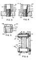
- the sleeve 144 is relieved via tapered surface 146 to partially receive the wedge washer 158. Also the support 112 is relieved via tapered surface 148 to receive the remaining portion of wedge washer 158. As a result any lateral movement of the sleeve 144 is opposed by the interference between the wedge washer and the bolt and also between the wedge washer and the support.
- the pin assembly 222 includes a sleeve 244 with a frusto conical surface 246 engageable with a tapered surface 248 of the support 212. Because the sleeve 244 is partially received within the recess 250 defining the tapered surface 248, lateral movement of the sleeve is opposed by the support 212. With this construction it is possible to eliminate a wedge washer adjacent the support 212. Also in figure 5, the bolt 352 of pin assembly 322 includes a frusto conical surface 354 engageable with a tapered surface 346 of sleeve 344 to retain the sleeve secured relative to the support and to oppose lateralmovement of the sleeve. Consequently, the structure of figure 5 eliminates the need for a wedge washer adjacent the bolt head 358.
- the pin assembly 422 which replaces the prior pin assemblies 22, 122, 222 and 322 comprises a bolt 452 with an outer surface 454 in substantially close sliding fit with the caliper opening 36. Because of the close sliding fit of bolt 452, the other pin assembly 24 is adapted to accommodate any lateral offset between openings 36 and 42 via the clearance 86, and also to accommodate angularity between the axis of opening 36 and pin assembly 24 via the arcuate washer 70 and 72.
- figure 2 shows the arcuate surfaces of the washers and the sleeve having radii of curvature extending in opposite directions, it is possible to reverse the concavity of the arcuate surfaces at each washer and its associated end of the sleeve, as shown in figure 6 at pin assembly 24.
Landscapes
- Engineering & Computer Science (AREA)
- General Engineering & Computer Science (AREA)
- Mechanical Engineering (AREA)
- Braking Arrangements (AREA)
Applications Claiming Priority (2)
| Application Number | Priority Date | Filing Date | Title |
|---|---|---|---|
| US06/179,322 US4334599A (en) | 1980-08-18 | 1980-08-18 | Disc brake and mounting pin assembly therefor |
| US179322 | 1980-08-18 |
Publications (2)
| Publication Number | Publication Date |
|---|---|
| EP0046432A2 true EP0046432A2 (de) | 1982-02-24 |
| EP0046432A3 EP0046432A3 (de) | 1982-03-03 |
Family
ID=22656082
Family Applications (1)
| Application Number | Title | Priority Date | Filing Date |
|---|---|---|---|
| EP81401290A Withdrawn EP0046432A3 (de) | 1980-08-18 | 1981-08-11 | Scheibenbremse |
Country Status (8)
| Country | Link |
|---|---|
| US (1) | US4334599A (de) |
| EP (1) | EP0046432A3 (de) |
| JP (1) | JPS5754739A (de) |
| AR (1) | AR224460A1 (de) |
| AU (1) | AU7398081A (de) |
| BR (1) | BR8105240A (de) |
| CA (1) | CA1172179A (de) |
| MX (1) | MX153226A (de) |
Cited By (9)
| Publication number | Priority date | Publication date | Assignee | Title |
|---|---|---|---|---|
| FR2550836A1 (fr) * | 1983-08-18 | 1985-02-22 | Lucas Ind Plc | Frein a disque a garniture partielle avec pince flottante |
| DE3635828A1 (de) * | 1986-10-22 | 1988-05-05 | Teves Gmbh Alfred | Teilbelag-scheibenbremse, insbesondere fuer kraftfahrzeuge |
| EP0451728A1 (de) * | 1990-04-05 | 1991-10-16 | Lucas Industries Public Limited Company | Teilbelag-Scheibenbremse für Kraftfahrzeuge |
| WO1994001693A1 (fr) * | 1992-07-10 | 1994-01-20 | Bendix Espana S.A. | Dispositif de guidage d'etrier coulissant pour frein a disque |
| EP0645551A1 (de) * | 1993-09-21 | 1995-03-29 | Sime Industrie | Schwimmsattel-Scheibenbremse |
| US5526904A (en) * | 1993-04-15 | 1996-06-18 | Lucas Industries Public Limited Company | Floating caliper brake, especially a floating caliper spot type disc brake |
| DE10143805B4 (de) * | 2001-09-06 | 2006-10-26 | Continental Teves Ag & Co. Ohg | Bolzenführungseinheit für eine Schwimmsattel-Scheibenbremse |
| WO2017076529A1 (de) * | 2015-11-05 | 2017-05-11 | Knorr-Bremse Systeme für Nutzfahrzeuge GmbH | Scheibenbremse für ein nutzfahrzeug |
| EP3779224A1 (de) * | 2019-08-16 | 2021-02-17 | Meritor Heavy Vehicle Braking Systems (UK) Limited | Halterung für einen führungsstift einer scheibenbremse |
Families Citing this family (43)
| Publication number | Priority date | Publication date | Assignee | Title |
|---|---|---|---|---|
| JPS626996Y2 (de) * | 1980-07-02 | 1987-02-18 | ||
| US4441592A (en) * | 1982-08-27 | 1984-04-10 | Kool-Stop International Inc. | Bicycle brake assembly |
| US4708397A (en) * | 1986-08-12 | 1987-11-24 | Weinmann Paul R | Motor vehicle wheel mounting means and method |
| US4732519A (en) * | 1986-12-24 | 1988-03-22 | Illinois Tool Works Inc. | Fastener assembly with axial play |
| US4867461A (en) * | 1988-03-01 | 1989-09-19 | J. L. French Corporation | Gasket sealing system |
| FR2631405B1 (fr) * | 1988-05-10 | 1993-02-19 | Bendix France | Frein a disque et systeme de support pour un tel frein |
| US4906036A (en) * | 1988-09-26 | 1990-03-06 | The Hartwell Corporation | Pivoting adjustment screw |
| IT1232064B (it) * | 1989-03-30 | 1992-01-23 | Fiat Auto Spa | Dispositivo di collegamento di parti meccaniche alla scocca di un autoveicolo |
| US5226510A (en) * | 1989-04-28 | 1993-07-13 | Bendix Europe Services Techniques | Disc brake with slidable caliper |
| US5326206A (en) * | 1993-04-19 | 1994-07-05 | Northrop Corporation | Method for compensating for bolt hole misalignment and bolt assemblies therefor |
| US5395194A (en) * | 1993-10-13 | 1995-03-07 | H. Thad Johnson | Convoluted bolt retainer |
| US5489177A (en) * | 1994-06-08 | 1996-02-06 | Crest Products, Inc. | Fastener assembly with axially captivated washer |
| JPH08169207A (ja) * | 1994-08-18 | 1996-07-02 | Bridgestone Metalpha Kk | 空気入りラジアルタイヤ |
| US5529150A (en) * | 1995-05-16 | 1996-06-25 | Hayes Industrial Brake, Inc. | Parking brake |
| ZA983955B (en) * | 1997-05-15 | 2001-08-13 | Sdgi Holdings Inc | Anterior cervical plating system. |
| US5807052A (en) * | 1997-06-27 | 1998-09-15 | Illinois Tool Works Inc. | Pre-assembled manifold fastener system and method therefor |
| US6030161A (en) * | 1998-06-23 | 2000-02-29 | Textron, Inc. | Sleeve and captive bolt assembly |
| US6039525A (en) * | 1998-10-21 | 2000-03-21 | Johnson; H. Thad | Integrated spring ring retainer for captivating a fastener to a workpiece |
| US6059503A (en) * | 1998-10-27 | 2000-05-09 | Johnson; H. Thad | Captivated fastener assembly |
| US6026909A (en) * | 1998-10-30 | 2000-02-22 | Techtronic Industries Co., Ltd. | Power tool |
| US6585468B2 (en) | 2001-02-02 | 2003-07-01 | H. Thad Johnson | Captivated fastener assembly with post-formed retention feature and method for forming the same |
| DE10150214B4 (de) * | 2001-10-12 | 2020-10-29 | Knorr-Bremse Systeme für Nutzfahrzeuge GmbH | Scheibenbremse, insbesondere für ein Nutzfahrzeug |
| US6794792B2 (en) * | 2002-11-13 | 2004-09-21 | General Electric Company | Cold structural enclosure for multi-pole rotor having super-conducting field coil windings. |
| US8172885B2 (en) * | 2003-02-05 | 2012-05-08 | Pioneer Surgical Technology, Inc. | Bone plate system |
| US8900277B2 (en) | 2004-02-26 | 2014-12-02 | Pioneer Surgical Technology, Inc. | Bone plate system |
| US7740649B2 (en) | 2004-02-26 | 2010-06-22 | Pioneer Surgical Technology, Inc. | Bone plate system and methods |
| US20070051568A1 (en) * | 2005-09-08 | 2007-03-08 | Akebono Corporation (North America) | Tapered pin design |
| US7682117B2 (en) * | 2006-09-27 | 2010-03-23 | Illinois Tool Works Inc. | Work piece isolating assembly |
| US7708512B2 (en) * | 2006-10-18 | 2010-05-04 | Newfrey Llc | Compression limiter |
| US7393015B1 (en) * | 2007-06-18 | 2008-07-01 | Honda Motor Co., Ltd. | Vehicle sub-frame attachment apparatus and method |
| WO2009006604A1 (en) | 2007-07-03 | 2009-01-08 | Pioneer Surgical Technology, Inc. | Bone plate system |
| US8361126B2 (en) | 2007-07-03 | 2013-01-29 | Pioneer Surgical Technology, Inc. | Bone plate system |
| US7753633B2 (en) * | 2007-11-14 | 2010-07-13 | Newfrey Llc | Power seal bolt assembly |
| US8920091B2 (en) * | 2008-04-29 | 2014-12-30 | Raytheon Company | Fastener with bilateral seal for liquid immersion cooling applications |
| CN103649579B (zh) * | 2011-06-07 | 2016-05-25 | 丰田自动车株式会社 | 盘式制动装置及制动钳滑动机构 |
| DE102012013957A1 (de) | 2012-07-13 | 2014-01-16 | Knorr-Bremse Systeme für Nutzfahrzeuge GmbH | Scheibenbremse für ein Nutzfahrzeug |
| DE102014106536B4 (de) * | 2014-05-09 | 2016-01-07 | Knorr-Bremse Systeme für Nutzfahrzeuge GmbH | Scheibenbremse für ein Nutzfahrzeug |
| US9551387B2 (en) * | 2015-02-06 | 2017-01-24 | Kelsey-Hayes Company | Disc brake assembly with guide pin locating feature |
| US10767715B2 (en) * | 2018-10-11 | 2020-09-08 | Bendix Spicer Foundation Brake Llc | Pivotable actuator mounting device |
| US11877779B2 (en) | 2020-03-26 | 2024-01-23 | Xtant Medical Holdings, Inc. | Bone plate system |
| CN114321218B (zh) * | 2020-09-29 | 2023-10-17 | 比亚迪股份有限公司 | 盘式制动器和具有其的车辆 |
| IT202100014294A1 (it) * | 2021-06-01 | 2022-12-01 | Brembo Spa | Pinza flottante |
| US20250084904A1 (en) * | 2023-09-12 | 2025-03-13 | Bendix Commercial Vehicle Systems Llc | Air disc brake system drag reduction guide pin and methods for the use and assembly thereof |
Family Cites Families (13)
| Publication number | Priority date | Publication date | Assignee | Title |
|---|---|---|---|---|
| US663464A (en) * | 1900-04-05 | 1900-12-11 | Samuel F Prince Jr | Boiler-stay. |
| US1411261A (en) * | 1921-04-25 | 1922-04-04 | Wickes Boiler Company | Stay bolt |
| US3220289A (en) * | 1963-04-24 | 1965-11-30 | Amsted Ind Inc | Intermediate shaft support bearing |
| GB1193641A (en) * | 1966-06-18 | 1970-06-03 | Girling Ltd | Disc Brake. |
| US3702125A (en) * | 1970-06-18 | 1972-11-07 | Dan W Jeffries | Compensating hydraulic brake structure with manual override |
| US3682277A (en) * | 1970-07-24 | 1972-08-08 | Girling Ltd | Disc brakes and mounting structure therefor |
| US3749362A (en) * | 1971-04-09 | 1973-07-31 | Nasa | Fastener stretcher |
| GB1519502A (en) * | 1974-08-29 | 1978-07-26 | Toyota Motor Co Ltd | Disc brake assembly with anti-rattle springs |
| GB1506718A (en) * | 1974-11-05 | 1978-04-12 | Girling Ltd | Disc brakes for vehicles |
| JPS52106781U (de) * | 1976-02-12 | 1977-08-13 | ||
| GB1572451A (en) * | 1976-06-01 | 1980-07-30 | Girling Ltd | Sliding caliper disc brake |
| JPS54144556A (en) * | 1978-04-30 | 1979-11-10 | Aisin Seiki Co Ltd | Disc brake |
| JPS5544107A (en) * | 1978-09-19 | 1980-03-28 | Aisin Seiki Co Ltd | Mounting structure of movable calliper in disk brake |
-
1980
- 1980-08-18 US US06/179,322 patent/US4334599A/en not_active Expired - Lifetime
-
1981
- 1981-08-06 CA CA000383310A patent/CA1172179A/en not_active Expired
- 1981-08-11 EP EP81401290A patent/EP0046432A3/de not_active Withdrawn
- 1981-08-11 AU AU73980/81A patent/AU7398081A/en not_active Abandoned
- 1981-08-14 MX MX188742A patent/MX153226A/es unknown
- 1981-08-17 BR BR8105240A patent/BR8105240A/pt not_active IP Right Cessation
- 1981-08-18 JP JP56128286A patent/JPS5754739A/ja active Pending
- 1981-08-18 AR AR286458A patent/AR224460A1/es active
Cited By (16)
| Publication number | Priority date | Publication date | Assignee | Title |
|---|---|---|---|---|
| GB2145175A (en) * | 1983-08-18 | 1985-03-20 | Lucas Ind Plc | A spot type disc brake |
| FR2550836A1 (fr) * | 1983-08-18 | 1985-02-22 | Lucas Ind Plc | Frein a disque a garniture partielle avec pince flottante |
| DE3635828A1 (de) * | 1986-10-22 | 1988-05-05 | Teves Gmbh Alfred | Teilbelag-scheibenbremse, insbesondere fuer kraftfahrzeuge |
| EP0451728A1 (de) * | 1990-04-05 | 1991-10-16 | Lucas Industries Public Limited Company | Teilbelag-Scheibenbremse für Kraftfahrzeuge |
| US5439084A (en) * | 1992-07-10 | 1995-08-08 | Bendix Espana S.A. | Device for a guiding sliding caliper for a disk-brake |
| WO1994001693A1 (fr) * | 1992-07-10 | 1994-01-20 | Bendix Espana S.A. | Dispositif de guidage d'etrier coulissant pour frein a disque |
| US5526904A (en) * | 1993-04-15 | 1996-06-18 | Lucas Industries Public Limited Company | Floating caliper brake, especially a floating caliper spot type disc brake |
| FR2710379A1 (fr) * | 1993-09-21 | 1995-03-31 | Sime Ind | Frein à disque à montage coulissant. |
| EP0645551A1 (de) * | 1993-09-21 | 1995-03-29 | Sime Industrie | Schwimmsattel-Scheibenbremse |
| DE10143805B4 (de) * | 2001-09-06 | 2006-10-26 | Continental Teves Ag & Co. Ohg | Bolzenführungseinheit für eine Schwimmsattel-Scheibenbremse |
| WO2017076529A1 (de) * | 2015-11-05 | 2017-05-11 | Knorr-Bremse Systeme für Nutzfahrzeuge GmbH | Scheibenbremse für ein nutzfahrzeug |
| CN108474424A (zh) * | 2015-11-05 | 2018-08-31 | 克诺尔商用车制动系统有限公司 | 用于商用车的盘式制动器 |
| US10900527B2 (en) | 2015-11-05 | 2021-01-26 | Knorr-Bremse Systeme Fuer Nutzfahrzeuge Gmbh | Disk brake for a utility vehicle |
| EP3779224A1 (de) * | 2019-08-16 | 2021-02-17 | Meritor Heavy Vehicle Braking Systems (UK) Limited | Halterung für einen führungsstift einer scheibenbremse |
| EP3779224B1 (de) | 2019-08-16 | 2022-10-05 | Meritor Heavy Vehicle Braking Systems (UK) Limited | Halterung für einen führungsstift einer scheibenbremse |
| US11603895B2 (en) | 2019-08-16 | 2023-03-14 | Meritor Heavy Vehicle Braking Systems (Uk) Limited | Mounting for a guide pin of a disc brake |
Also Published As
| Publication number | Publication date |
|---|---|
| AU7398081A (en) | 1982-02-25 |
| JPS5754739A (en) | 1982-04-01 |
| BR8105240A (pt) | 1982-04-27 |
| US4334599A (en) | 1982-06-15 |
| EP0046432A3 (de) | 1982-03-03 |
| CA1172179A (en) | 1984-08-07 |
| AR224460A1 (es) | 1981-11-30 |
| MX153226A (es) | 1986-08-26 |
Similar Documents
| Publication | Publication Date | Title |
|---|---|---|
| EP0046432A2 (de) | Scheibenbremse | |
| US4281745A (en) | Brake disk for disk brakes on a rail vehicle | |
| US4181217A (en) | Conveyor-belt drum | |
| US6988598B2 (en) | Disc brake rotor mounting system | |
| US5947234A (en) | Disc brake | |
| US4798268A (en) | Multiple disc brake | |
| JP2000018291A (ja) | ラジアルマウント型ディスクブレーキ | |
| US4082167A (en) | Sliding caliper-type disc brake and support structure therefore | |
| EP0826894B1 (de) | Scheibenbremsvorrichtung | |
| EP3682133B1 (de) | Scheibenbremsrotoranordnung | |
| US4265341A (en) | Easy-to-assemble sliding arrangement in disc brake | |
| JPH0556411B2 (de) | ||
| US5439077A (en) | Brake disk for wheel disk brakes | |
| EP0096553B1 (de) | Scheibenzusammensetzungen für Bremsen | |
| US4476962A (en) | Disc brake having a sliding yoke | |
| CN112524180B (zh) | 包括具有分段摩擦环的制动盘的轨道轮 | |
| US4696376A (en) | Configuration for a disk brake torque tube | |
| US4460070A (en) | Spot-type brake | |
| CA1171003A (en) | Disc brake caliper support | |
| US5845764A (en) | Wear element for screw presses or the like | |
| US4051925A (en) | Disc brakes for vehicles including a screw-threaded draw bar assembly | |
| US6533079B2 (en) | Disc brake | |
| GB2033989A (en) | Floating-caliper Disc Brake | |
| US4732242A (en) | Spot-type disc brake for vehicles | |
| JP2566307B2 (ja) | スポット型ディスクブレーキ |
Legal Events
| Date | Code | Title | Description |
|---|---|---|---|
| PUAI | Public reference made under article 153(3) epc to a published international application that has entered the european phase |
Free format text: ORIGINAL CODE: 0009012 |
|
| PUAL | Search report despatched |
Free format text: ORIGINAL CODE: 0009013 |
|
| 17P | Request for examination filed |
Effective date: 19810821 |
|
| AK | Designated contracting states |
Designated state(s): DE FR GB IT |
|
| AK | Designated contracting states |
Designated state(s): DE FR GB IT |
|
| STAA | Information on the status of an ep patent application or granted ep patent |
Free format text: STATUS: THE APPLICATION IS DEEMED TO BE WITHDRAWN |
|
| 18D | Application deemed to be withdrawn |
Effective date: 19840216 |
|
| RIN1 | Information on inventor provided before grant (corrected) |
Inventor name: RITSEMA, IRVING RAY Inventor name: WOO, JI YAH |