EP0046484A2 - Véhicule articulé à plusieurs essieux - Google Patents
Véhicule articulé à plusieurs essieux Download PDFInfo
- Publication number
- EP0046484A2 EP0046484A2 EP81104302A EP81104302A EP0046484A2 EP 0046484 A2 EP0046484 A2 EP 0046484A2 EP 81104302 A EP81104302 A EP 81104302A EP 81104302 A EP81104302 A EP 81104302A EP 0046484 A2 EP0046484 A2 EP 0046484A2
- Authority
- EP
- European Patent Office
- Prior art keywords
- articulated
- brake
- primary
- vehicle according
- car
- Prior art date
- Legal status (The legal status is an assumption and is not a legal conclusion. Google has not performed a legal analysis and makes no representation as to the accuracy of the status listed.)
- Granted
Links
Images


Classifications
-
- B—PERFORMING OPERATIONS; TRANSPORTING
- B62—LAND VEHICLES FOR TRAVELLING OTHERWISE THAN ON RAILS
- B62D—MOTOR VEHICLES; TRAILERS
- B62D47/00—Motor vehicles or trailers predominantly for carrying passengers
- B62D47/02—Motor vehicles or trailers predominantly for carrying passengers for large numbers of passengers, e.g. omnibus
- B62D47/025—Motor vehicles or trailers predominantly for carrying passengers for large numbers of passengers, e.g. omnibus articulated buses with interconnecting passageway, e.g. bellows
-
- B—PERFORMING OPERATIONS; TRANSPORTING
- B62—LAND VEHICLES FOR TRAVELLING OTHERWISE THAN ON RAILS
- B62D—MOTOR VEHICLES; TRAILERS
- B62D53/00—Tractor-trailer combinations; Road trains
- B62D53/04—Tractor-trailer combinations; Road trains comprising a vehicle carrying an essential part of the other vehicle's load by having supporting means for the front or rear part of the other vehicle
- B62D53/06—Semi-trailers
Definitions
- the invention relates to an articulated vehicle with a plurality of axles, in particular an articulated bus, which has a primary and secondary car, in which at least the axis of the secondary car is driven via a drive motor, in particular associated with the secondary car, and in which the secondary car is connected to the primary car via an articulated connection , in particular the front axle of the primary car being provided for steering the vehicle.
- Articulated vehicles of this type are known as articulated buses.
- a slewing ring is arranged between the primary carriage and the secondary carriage, which forms the pivot point of the secondary carriage to the primary carriage, the vehicle bodies being replaced laterally by bellows in this area.
- the secondary car forms an articulation angle with the primary car and therefore the thrust forces of the secondary car, depending on the articulation angle, act differently on the primary car along a tangent that is to be thought of as the circle formed by the curve to be driven . Without special support between the primary and secondary cars, this would result in the primary car being severely impaired in its cornering position.
- the invention has for its object to design an articulated vehicle, in particular an articulated bus so that it can be safely controlled even on wet or slippery road surfaces, even when cornering heavily, without the vehicle breaking out or kinking between the secondary and the primary car needs to be feared.
- the invention consists in that an articulated brake is provided which acts on the articulated connection as a function of the articulation angle between the primary and secondary car.
- an articulated brake acts on the articulated connection as a function of the articulation angle between the primary and secondary car.
- the articulated brake can develop its maximum braking force so that the articulation angle can be determined beforehand, so that a further increase in the articulation angle can no longer occur.
- the articulated brake is inefficient and increases its braking force to the extent by the bend angle is increased by a ven mars originally K.
- the braking forces perpendicular to the direction of thrust of the secondary carriage can only act on the primary carriage between surfaces suitably provided on the joint. Only significantly smaller braking forces are required for this.
- the joint brake can be for example a pneumatically operated R egg environment brake.
- Articulated vehicles of this type are usually equipped with compressed air units, which can therefore also be used to actuate the articulated brake without the need to provide an additional auxiliary power supply to a vehicle with the articulated brake according to the invention.
- a friction brake can be effectively arranged in the area of the connection between the two car halves and act in such a way that it can prevent a further increase in this angle at the largest permitted articulation angle.
- the brake can of course also be an oil pressure-actuated disc brake.
- a mechanical step switch is provided in the area of the slewing ring, which consists of a step wheel that increases its circumference in steps and comes into contact with mechanical switching points when the appropriate kink angle is reached.
- the switching points can control the compressed air supply to the friction brake via solenoid valves when acted on by the stepped wheel. In most cases, such a tap change will suffice to allow the braking effect to occur constantly within the angle range defined by the tap changer. It can also be inexpensive to provide a stepless switch that enables angle-dependent control.
- This configuration also opens up the possibility of triggering other control processes. For example, it is possible to trigger a warning signal for the driver when the maximum articulation angle is reached or, for automatic transmissions and reverse driving, where the maximum articulation angle can be reached, to automatically switch the reverse gear into neutral. This avoids overloading the chassis.
- the articulated brake is applied when the service brake is actuated. This can prevent the secondary car from breaking out compared to the primary car when the brakes are applied hard. In particular, it is fixed in its position in relation to the primary carriage by fully applying the articulated brake. Rolling movements or a lateral displacement can then no longer occur.
- both the service brake and the articulated brake are applied via the switches.
- the result of this is that no greater than the maximum articulation angle can occur, since the vehicle is braked immediately in this case. Damage that would be caused to the body of both the primary and the secondary car when this angle is exceeded can be effectively avoided in this way.
- steering shock absorbers can also be provided in a favorable manner between the primary and the secondary vehicle, each of which is located on the opposite vehicle support sides and can be arranged at an angle to the longitudinal axis of the vehicle.
- These steering shock absorbers have the advantage that they can dampen a rolling movement of the secondary carriage when driving straight ahead.
- the articulated brake can be controlled in such a way that it occurs at small articulation angles, such as, for example. caused by rolling movements, does not respond. This control could also be carried out while driving straight ahead by means of a corresponding control of the articulated brake according to the invention, but this would require a more extensive control.
- the steering shock absorbers can also be designed such that they block when a predetermined buckling speed is exceeded, so that a further kinking of primary and secondary cars is avoided .
- the tank and / or all other heavy attachments between the rear axle and the joint are attached as close as possible to the joint.
- the support load of the secondary carriage in the joint can be greater. This prevents lurching movements and makes the connection between the two vehicles more secure.
- the invention also opens up the possibility of applying a partial brake pressure to the articulated brake at high driving speeds, so that straight-ahead driving is also stabilized.
- the design according to the invention has the advantage that the articulated brake can be provided with an axle bolt fixedly connected to the primary carriage via a fastening arm, which is anyway required for the articulated brake, and that this axle bolt on the side facing away from the fastening arm can be used to provide an actuating arm for the handlebar to the steered axles of the secondary carriage to fix.
- This embodiment allows a space-saving arrangement in which there are no difficulties for the accommodation of the articulated brake, the shock absorber and the actuation for the additional steering on the secondary carriage.
- the secondary carriage 1 shows an articulated bus, in which 1 denotes a secondary car and 2 a primary car, which are connected to one another via an articulated connection 3.
- the secondary carriage 1 carries the drive unit 6 and can be controlled from the primary carriage via the steerable axle 5.
- the two carriages are laterally connected to each other via bellows in the area of the articulated connection, as is the case with articulated buses, for example.
- an articulated cable is usually equipped with a service brake 21, which is shown only schematically in FIG Axis 5a is shown. It is provided that such a service brake 21 interacts with the articulated brake 11 arranged in the area of the articulated connection 3 in such a way that it is fully acted upon when the service brake 21 is actuated.
- the drive unit as a central motor 6 'for driving the axis 5a. However, the load in the area of the articulated connection 3 becomes lower when the drive unit 6 is arranged in the secondary carriage.
- Such an articulated vehicle is shown schematically in cornering in FIG. 2.
- the secondary carriage 1 and the primary carriage 2 form an articulation angle 0 (with one another, which is established as a function of the steering deflection of the steering wheels 5.
- articulation angle 0 With one another, which is established as a function of the steering deflection of the steering wheels 5.
- shear forces occur on the primary carriage, which originate from the secondary carriage 1 and are not completely in the direction of the Act longitudinal axis of the primary carriage 2.
- an articulated brake 11 in the articulated connection 3 which is indicated in FIGS. 1 and 2 and can be seen schematically from FIG. 3 and is designed, for example, in the manner of a pressure-actuated disc or multi-disc brake is.
- the articulation is between the two opposite ends 1a and 2a of the two carriages 1 and 2 are manufactured in such a way that a fastening arm 8, which is fastened to the primary carriage 2, is connected in a rotationally fixed manner to an axle bolt 9, on which brake disks 9a and 9b can be provided.
- the articulated brake can be, for example, a compressed air-actuated friction brake, which is acted upon via a compressed air line 17 by one of the two carriages, which also carries the compressed air unit usually located on such articulated vehicles, in a manner not shown in detail.
- Adherence to a certain articulation angle can then be ensured by the articulated brake 11 with considerably lower forces, the articulated brake being able to be controlled such that it develops an ever increasing braking force with increasing articulation angles.
- the occurring thrust forces of the secondary carriage 1 can therefore no longer cause blocking forces which could have negative effects on the chassis and the body.
- the axle pin 9 which coincides with the hinge axis in the exemplary embodiment, can also be used to force the steering of one - or more - axis 7 of the secondary carriage to effect.
- the axle pin 9 With increasing total length of the articulated bus, it becomes necessary with a view to complying with certain prescribed curve radii in addition to the axis 5 of the primary car 2 and the axle 7 of the secondary car 1, which in a conventional manner via a steerable arrangement of the wheels Axis 7 and via a tie rod 25 assigned to this and a steering rod 26 leading to the primary carriage 2.
- the handlebar 26 can now be hinged in a very simple manner to an actuating arm 27 which is connected in a rotationally fixed manner to the axle pin 9. Since this axle pin 9 is firmly connected to the primary carriage 2 via the fastening arm 8, the wheels of the axle 7 are inevitably steered when cornering (FIG. 2). There are no space problems when accommodating the linkage of the steering rod 26 on the primary car, although in the area of the articulated connection 3 the articulated brake 11 and, as will be explained below, a control device for the articulated brake 11 and shock absorber 15 are arranged.
- axle pin 9 penetrates the brake housing 10 in a sealed manner upwards and on this, its end facing away from the fastening arm 8, is firmly provided with the actuating arm 27 which has a ball joint pin 28 for articulating the handlebar 26 can carry.
- a stepped washer 12 which is arranged, for example, in the region of a swivel ring 14 which forms the joint between primary carriage 2 and secondary carriage 1 and is shown in FIG. 4 and which is fixed with one of the two Carriages, for example the primary carriage 2, are connected via the axle bolts 9 which are fixedly arranged thereon.
- switches 18 can then be actuated in a simple manner, depending on the articulation angle, which are mounted on a holder 19, which in turn is firmly connected to the other carriage, that is to say in the case of the secondary carriage 1, in a manner not shown.
- the signals emanating from the switches 18 can then be sent to known solenoid valves 20, which can regulate the compressed air supply via the supply line 17 into the articulated brake 11 accordingly.
- the control takes place so that the articulated brake becomes ineffective in straight-ahead travel and its braking force increases with increasing articulation angles by opening the stepped disc by the rotary movement in one of the arrow directions of the switch 18 and one with increasing angles several solenoid valves 20, so that at maximum braking force, the sum of the pressures passed through the individual valves is present in the compressed air line 17 and applies the brake.
- the articulated brake can then have developed its maximum braking force, as a result of which a further kinking and thus an increase in the articulation angle ⁇ between the two carriages 1 and 2 can no longer take place.
- This blocking takes place in such a way that the secondary carriage 1 does not support itself on the primary carriage 2 mechanically via shock absorbers which are under maximum tension in this case, but prevents a further rotational movement in the joint 3 itself.
- the articulated brake can remain switched off within a certain, small angular range.
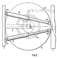
- the rolling movements of the secondary carriage 1 in relation to the primary carriage 2 which then occur when driving straight ahead can be absorbed in a simple manner via two steering shock absorbers 15, the arrangement of which in the region of the turntable 14 is also shown schematically in FIG. 5.
- They can be arranged, for example, above the articulated brake 11 in such a way that they are supported at one end 15a on a carriage, for example 2, and with the other end 15b on the carriage 1.
- the shock absorbers 15 can be arranged in such a way that they are r. it the connecting axis of the two carriage halves 1 and 2 form an angle ⁇ .
- the damper functions are then increasingly taken over by the articulated brake 11. It is also advantageous if a partial brake pressure is generated in the articulated brake 11 at high driving speeds, which is used for stabilization when driving straight ahead.
- control can be carried out via the switch 18 in such a way that the service brake 21 is also acted on at the same time. This makes it impossible for this maximum articulation angle ⁇ to be exceeded, as a result of which the body of both the primary and the secondary car would be damaged.
- the articulated brake significantly increases the ability of articulated vehicles to corner, even on wet and slippery roads.
- an articulated brake operating according to the invention can also be advantageously used in the joints of other vehicles which are connected to one another via an articulation. If the articulated brake is applied via the service brake, the secondary carriage can be effectively prevented from breaking out in relation to the primary carriage, both when driving straight ahead and when cornering.
Landscapes
- Engineering & Computer Science (AREA)
- Chemical & Material Sciences (AREA)
- Combustion & Propulsion (AREA)
- Transportation (AREA)
- Mechanical Engineering (AREA)
- Vehicle Body Suspensions (AREA)
- Steering-Linkage Mechanisms And Four-Wheel Steering (AREA)
- Body Structure For Vehicles (AREA)
- Steering Control In Accordance With Driving Conditions (AREA)
- Arrangement Or Mounting Of Propulsion Units For Vehicles (AREA)
- Air-Conditioning For Vehicles (AREA)
Priority Applications (1)
| Application Number | Priority Date | Filing Date | Title |
|---|---|---|---|
| AT81104302T ATE33801T1 (de) | 1980-08-23 | 1981-06-04 | Gelenkfahrzeug mit mehreren achsen. |
Applications Claiming Priority (2)
| Application Number | Priority Date | Filing Date | Title |
|---|---|---|---|
| DE3031862A DE3031862C2 (de) | 1980-08-23 | 1980-08-23 | Gelenkfahrzeug mit mehreren Achsen |
| DE3031862 | 1980-08-23 |
Publications (3)
| Publication Number | Publication Date |
|---|---|
| EP0046484A2 true EP0046484A2 (fr) | 1982-03-03 |
| EP0046484A3 EP0046484A3 (en) | 1982-11-10 |
| EP0046484B1 EP0046484B1 (fr) | 1988-04-27 |
Family
ID=6110262
Family Applications (1)
| Application Number | Title | Priority Date | Filing Date |
|---|---|---|---|
| EP81104302A Expired EP0046484B1 (fr) | 1980-08-23 | 1981-06-04 | Véhicule articulé à plusieurs essieux |
Country Status (6)
| Country | Link |
|---|---|
| US (1) | US4469347A (fr) |
| EP (1) | EP0046484B1 (fr) |
| AT (1) | ATE33801T1 (fr) |
| CA (1) | CA1164498A (fr) |
| DE (2) | DE3031862C2 (fr) |
| HU (1) | HU193631B (fr) |
Cited By (6)
| Publication number | Priority date | Publication date | Assignee | Title |
|---|---|---|---|---|
| WO1984000730A1 (fr) * | 1982-08-18 | 1984-03-01 | Falkenried Fahrzeug Gmbh | Procede de reglage de la resistance au pivotement lateral de vehicules routiers comprenant au moins deux parties du vehicule reliees par une unite d'articulation et unite d'articulation pour la mise en oeuvre du procede |
| EP0161472A3 (fr) * | 1984-05-16 | 1987-08-26 | AUTOTRASPORTI PADOVA ATP S.p.A. | Dispositif de contrôle de l'angle relatif entre un tracteur et une semi-remorque |
| US4763916A (en) * | 1984-02-24 | 1988-08-16 | Autoipari Kutato Es Fejleszto Vallalat | Hydraulic jackknifing-affecting apparatus for articulated vehicles |
| EP0381930A3 (fr) * | 1989-02-07 | 1991-09-04 | MAURI & C. S.a.s. di MAURI Ambrogio e ZORLONI Costanza | Module de contrôle de la plate-forme rotative d'un véhicule articulé à trois essieux |
| EP0475340A1 (fr) * | 1990-09-10 | 1992-03-18 | HYMER LEICHTMETALLBAU GmbH & Co. KG | Articulation pour autobus surbaissé et articulé |
| EP2570335A3 (fr) * | 2011-09-16 | 2018-10-17 | Samco Agricultural Manufacturing Limited | Remorque et procédé et appareil pour couplage de remorque à un attelage trois points d'un tracteur |
Families Citing this family (17)
| Publication number | Priority date | Publication date | Assignee | Title |
|---|---|---|---|---|
| DE3623668A1 (de) * | 1986-07-12 | 1988-01-14 | Man Nutzfahrzeuge Gmbh | Knickschutzbremse fuer gelenkomnibus |
| US5016899A (en) * | 1989-12-14 | 1991-05-21 | Leonard Euteneier | No-slack restricted-drum stabilizer for commercial multitrailer combinations |
| US5957476A (en) * | 1996-02-28 | 1999-09-28 | Simpson; William A. | Anti-jackknife system for tractor-trailers |
| AU770359B2 (en) | 1999-02-26 | 2004-02-19 | Shell Internationale Research Maatschappij B.V. | Liner hanger |
| FI117795B (fi) * | 2001-12-21 | 2007-02-28 | John Deere Forestry Oy | Nivelajoneuvon stabilointi |
| PL1531117T3 (pl) * | 2003-11-15 | 2006-10-31 | Huebner Gmbh | Ciągnik z przyczepą, szczególnie dwuosiową |
| KR100892715B1 (ko) | 2007-12-07 | 2009-04-15 | 현대자동차주식회사 | 대형굴절버스 차선제어 보조시스템 |
| HU229757B1 (hu) * | 2011-11-02 | 2014-06-30 | Istvan Dr Szabo | Két forgáspontú futómûves csuklóegység közúti jármûvekhez |
| WO2015095727A2 (fr) | 2013-12-20 | 2015-06-25 | Barnet Corbin | Système chirurgical et méthodes associées |
| EP3227169B1 (fr) | 2014-12-02 | 2020-08-12 | Husqvarna AB | Robot de tondeuse à gazon à transmission intégrale |
| CN105361983B (zh) * | 2015-09-14 | 2017-05-10 | 张英华 | 机器人及其控制方法 |
| US10040327B2 (en) * | 2016-05-10 | 2018-08-07 | Deere & Company | Oscillation control system and method |
| EP3484265A1 (fr) | 2016-07-12 | 2019-05-22 | Husqvarna AB | Véhicule robotisé à transmission intégrale doté de frein de direction |
| DE102017003148A1 (de) * | 2017-03-31 | 2018-10-04 | Scania Cv Ab | Verfahren und System zum Steuern eines Gelenkfahrzeugs |
| DE102019127269A1 (de) * | 2019-10-10 | 2021-04-15 | Schaeffler Technologies AG & Co. KG | Knicklenkerfahrzeug und Verfahren zur sicheren Lenkung und Spurhaltung eines Knicklenkerfahrzeugs |
| US11548573B1 (en) * | 2021-08-20 | 2023-01-10 | David M Regen | Jackknife prevention apparatus |
| JP7758611B2 (ja) * | 2022-03-23 | 2025-10-22 | 株式会社ジェイテクト | 連結車両の制御装置 |
Family Cites Families (19)
| Publication number | Priority date | Publication date | Assignee | Title |
|---|---|---|---|---|
| US2201353A (en) * | 1938-03-19 | 1940-05-21 | Harold A Soulis | Motor vehicle construction |
| US2213221A (en) * | 1939-07-26 | 1940-09-03 | Clarence B Johnson | Fifth-wheel mechanism |
| DE847256C (de) * | 1950-08-03 | 1952-08-21 | Erhard Huebner | Schlingerbremse fuer Lastwagenanhaenger |
| US3093713A (en) * | 1959-11-06 | 1963-06-11 | Grigsby Company Inc | Electrical component assembly |
| US3005643A (en) * | 1960-11-04 | 1961-10-24 | Frank C Dugan | Braking system for truck trailers |
| GB1075802A (en) * | 1963-08-29 | 1967-07-12 | Frederick John Charles Hope | Anti jack-knife device for use with fifth-wheel couplings particularly on articulated vehicles |
| GB1240554A (en) * | 1967-07-20 | 1971-07-28 | Isuzu Motors Ltd | Tractor-trailer combinations comprising anti-jack-knife devices |
| US3512803A (en) * | 1967-10-02 | 1970-05-19 | Mather Co | Stabilizing device for articulated vehicles |
| GB1307061A (en) * | 1969-01-31 | 1973-02-14 | Monnery D W | Articulated vehicle control system |
| US3580610A (en) * | 1969-05-06 | 1971-05-25 | Robert C Warren | Automatic antijackknifing control for articulated vehicles |
| US3819234A (en) * | 1972-03-06 | 1974-06-25 | Kelsey Hayes Co | Trailer sway control system |
| DE2420203C3 (de) * | 1974-04-26 | 1987-09-10 | Hamburger Hochbahn Ag, 2000 Hamburg | Einrichtung zum Schutz eines Gelenk- Straßenfahrzeugs gegen übermäßiges Einknicken |
| HU173149B (hu) * | 1975-07-14 | 1979-03-28 | Autoipari Kutato Intezet | Protivoskladnoe ustrojstvo k avtopoezdu |
| DE2547487A1 (de) * | 1975-10-23 | 1977-04-28 | Bosch Gmbh Robert | Fahrzeug bestehend aus fuehrungsteil und schubteil |
| DE2748713C2 (de) * | 1977-10-29 | 1986-11-27 | Daimler-Benz Ag, 7000 Stuttgart | Vorrichtung zur Beeinflussung des Knickwinkels für einen Gelenkzug |
| DE2810651A1 (de) * | 1978-03-11 | 1979-09-13 | Maschf Augsburg Nuernberg Ag | Zweigliedriger omnibus |
| DE2919831A1 (de) * | 1979-05-16 | 1980-11-20 | Maschf Augsburg Nuernberg Ag | Gelenkfahrzeug mit einer schutzvorrichtung gegen uebermaessiges einknicken |
| US4313616A (en) * | 1979-05-18 | 1982-02-02 | Howard D U | Speed responsive trailer stabilizer with zero slack |
| HU179667B (en) * | 1979-12-28 | 1982-11-29 | Autoipari Kutato Intezet | Turn angle limiting device for jointed vehicle |
-
1980
- 1980-08-23 DE DE3031862A patent/DE3031862C2/de not_active Expired
-
1981
- 1981-06-04 DE DE8181104302T patent/DE3176720D1/de not_active Expired
- 1981-06-04 EP EP81104302A patent/EP0046484B1/fr not_active Expired
- 1981-06-04 AT AT81104302T patent/ATE33801T1/de not_active IP Right Cessation
- 1981-08-18 HU HU812422A patent/HU193631B/hu unknown
- 1981-08-18 US US06/294,060 patent/US4469347A/en not_active Expired - Fee Related
- 1981-08-19 CA CA000384161A patent/CA1164498A/fr not_active Expired
Cited By (7)
| Publication number | Priority date | Publication date | Assignee | Title |
|---|---|---|---|---|
| WO1984000730A1 (fr) * | 1982-08-18 | 1984-03-01 | Falkenried Fahrzeug Gmbh | Procede de reglage de la resistance au pivotement lateral de vehicules routiers comprenant au moins deux parties du vehicule reliees par une unite d'articulation et unite d'articulation pour la mise en oeuvre du procede |
| US4688818A (en) * | 1982-08-18 | 1987-08-25 | Juergen Grassmuck | Method for regulating the bending stability of road vehicles |
| US4763916A (en) * | 1984-02-24 | 1988-08-16 | Autoipari Kutato Es Fejleszto Vallalat | Hydraulic jackknifing-affecting apparatus for articulated vehicles |
| EP0161472A3 (fr) * | 1984-05-16 | 1987-08-26 | AUTOTRASPORTI PADOVA ATP S.p.A. | Dispositif de contrôle de l'angle relatif entre un tracteur et une semi-remorque |
| EP0381930A3 (fr) * | 1989-02-07 | 1991-09-04 | MAURI & C. S.a.s. di MAURI Ambrogio e ZORLONI Costanza | Module de contrôle de la plate-forme rotative d'un véhicule articulé à trois essieux |
| EP0475340A1 (fr) * | 1990-09-10 | 1992-03-18 | HYMER LEICHTMETALLBAU GmbH & Co. KG | Articulation pour autobus surbaissé et articulé |
| EP2570335A3 (fr) * | 2011-09-16 | 2018-10-17 | Samco Agricultural Manufacturing Limited | Remorque et procédé et appareil pour couplage de remorque à un attelage trois points d'un tracteur |
Also Published As
| Publication number | Publication date |
|---|---|
| DE3031862C2 (de) | 1983-11-03 |
| CA1164498A (fr) | 1984-03-27 |
| ATE33801T1 (de) | 1988-05-15 |
| EP0046484A3 (en) | 1982-11-10 |
| HU193631B (en) | 1987-11-30 |
| DE3176720D1 (en) | 1988-06-01 |
| US4469347A (en) | 1984-09-04 |
| DE3031862A1 (de) | 1982-03-04 |
| EP0046484B1 (fr) | 1988-04-27 |
Similar Documents
| Publication | Publication Date | Title |
|---|---|---|
| EP0046484B1 (fr) | Véhicule articulé à plusieurs essieux | |
| DE3342355C2 (fr) | ||
| EP0141093B1 (fr) | Suspension pour des roues avant dirigeables de véhicules automobiles | |
| DE3926665C2 (de) | Radaufhängung für Kraftfahrzeuge | |
| DE3507141C2 (fr) | ||
| WO2007118629A1 (fr) | FUSéE D'ESSIEU POUR VéHICULE | |
| DD203706A5 (de) | Stabilisierungsvorrichtung fuer fahrzeugachsen | |
| DE3441560C2 (fr) | ||
| DE3514823A1 (de) | Unabhaengige radaufhaengung fuer kraftfahrzeuge | |
| DE3744089C1 (de) | Kraftfahrzeuglenkung | |
| EP1565370B1 (fr) | Palier pivotant et essieu orientable muni d'un tel palier | |
| DE69310779T2 (de) | Hinterradlenkeinrichtung | |
| DE69013517T2 (de) | Vierradlenkungssystem. | |
| DE60004214T2 (de) | Selbstlenkende achse | |
| EP4598758A1 (fr) | Système de suspension de roue de véhicule à moteur, et véhicule à moteur | |
| DE3912520B4 (de) | Hinterachse für ein Kraftfahrzeug | |
| CH670426A5 (fr) | ||
| DE102022104584A1 (de) | Lenksystem und lenkbare Achse für ein Kraftfahrzeug | |
| DE4134501A1 (de) | Lastwagen, insbesondere sattelauflieger | |
| DD202121A5 (de) | Vorrichtung zur beeinflussung des knickwinkels mittels reibungsbremsen fuer einen gelenkzug | |
| DE2332387A1 (de) | Radaufhaengung fuer gelenkte raeder von kraftfahrzeugen | |
| DE102020123524B4 (de) | Radmodul für ein Kraftfahrzeug | |
| DE2263506A1 (de) | Steuervorrichtung fuer einen anhaengewagen | |
| EP2871114B1 (fr) | Essieu directeur | |
| DD244316A5 (de) | Verankerungssystem fuer starre achsen von fahrzeugen mit staarr an dem fahrgestell befestigten, vertikal beweglichen aufhaengungen |
Legal Events
| Date | Code | Title | Description |
|---|---|---|---|
| PUAI | Public reference made under article 153(3) epc to a published international application that has entered the european phase |
Free format text: ORIGINAL CODE: 0009012 |
|
| AK | Designated contracting states |
Designated state(s): AT BE CH DE FR GB IT LI LU NL SE |
|
| PUAL | Search report despatched |
Free format text: ORIGINAL CODE: 0009013 |
|
| AK | Designated contracting states |
Designated state(s): AT BE CH DE FR GB IT LI LU NL SE |
|
| 17P | Request for examination filed |
Effective date: 19830413 |
|
| RAP1 | Party data changed (applicant data changed or rights of an application transferred) |
Owner name: DIAMOIL S.A. |
|
| RAP1 | Party data changed (applicant data changed or rights of an application transferred) |
Owner name: SCHENK FAHRZEUGWERK GMBH |
|
| RAP1 | Party data changed (applicant data changed or rights of an application transferred) |
Owner name: SCHENK FAHRZEUGWERK GMBH |
|
| RAP1 | Party data changed (applicant data changed or rights of an application transferred) |
Owner name: HYMER-LEICHTMETALLBAU |
|
| RAP1 | Party data changed (applicant data changed or rights of an application transferred) |
Owner name: HYMER-LEICHTMETALLBAU |
|
| GRAA | (expected) grant |
Free format text: ORIGINAL CODE: 0009210 |
|
| AK | Designated contracting states |
Kind code of ref document: B1 Designated state(s): AT BE CH DE FR GB IT LI LU NL SE |
|
| REF | Corresponds to: |
Ref document number: 33801 Country of ref document: AT Date of ref document: 19880515 Kind code of ref document: T |
|
| ITF | It: translation for a ep patent filed | ||
| REF | Corresponds to: |
Ref document number: 3176720 Country of ref document: DE Date of ref document: 19880601 |
|
| ET | Fr: translation filed | ||
| PG25 | Lapsed in a contracting state [announced via postgrant information from national office to epo] |
Ref country code: LU Free format text: LAPSE BECAUSE OF NON-PAYMENT OF DUE FEES Effective date: 19880630 |
|
| GBT | Gb: translation of ep patent filed (gb section 77(6)(a)/1977) | ||
| PLBE | No opposition filed within time limit |
Free format text: ORIGINAL CODE: 0009261 |
|
| STAA | Information on the status of an ep patent application or granted ep patent |
Free format text: STATUS: NO OPPOSITION FILED WITHIN TIME LIMIT |
|
| 26N | No opposition filed | ||
| PG25 | Lapsed in a contracting state [announced via postgrant information from national office to epo] |
Ref country code: SE Effective date: 19890605 |
|
| PG25 | Lapsed in a contracting state [announced via postgrant information from national office to epo] |
Ref country code: BE Effective date: 19890630 |
|
| BERE | Be: lapsed |
Owner name: HYMER-LEICHTMETALLBAU Effective date: 19890630 |
|
| PG25 | Lapsed in a contracting state [announced via postgrant information from national office to epo] |
Ref country code: NL Effective date: 19900101 |
|
| NLV4 | Nl: lapsed or anulled due to non-payment of the annual fee | ||
| PG25 | Lapsed in a contracting state [announced via postgrant information from national office to epo] |
Ref country code: FR Free format text: LAPSE BECAUSE OF NON-PAYMENT OF DUE FEES Effective date: 19900228 |
|
| REG | Reference to a national code |
Ref country code: FR Ref legal event code: ST |
|
| PGFP | Annual fee paid to national office [announced via postgrant information from national office to epo] |
Ref country code: GB Payment date: 19920616 Year of fee payment: 12 |
|
| PG25 | Lapsed in a contracting state [announced via postgrant information from national office to epo] |
Ref country code: GB Effective date: 19930604 |
|
| PGFP | Annual fee paid to national office [announced via postgrant information from national office to epo] |
Ref country code: AT Payment date: 19930618 Year of fee payment: 13 |
|
| ITTA | It: last paid annual fee | ||
| PGFP | Annual fee paid to national office [announced via postgrant information from national office to epo] |
Ref country code: CH Payment date: 19930827 Year of fee payment: 13 |
|
| GBPC | Gb: european patent ceased through non-payment of renewal fee |
Effective date: 19930604 |
|
| PG25 | Lapsed in a contracting state [announced via postgrant information from national office to epo] |
Ref country code: AT Effective date: 19940604 |
|
| PG25 | Lapsed in a contracting state [announced via postgrant information from national office to epo] |
Ref country code: LI Effective date: 19940630 Ref country code: CH Effective date: 19940630 |
|
| EUG | Se: european patent has lapsed |
Ref document number: 81104302.5 Effective date: 19900412 |
|
| REG | Reference to a national code |
Ref country code: CH Ref legal event code: PL |
|
| PGFP | Annual fee paid to national office [announced via postgrant information from national office to epo] |
Ref country code: DE Payment date: 19950704 Year of fee payment: 15 |
|
| PG25 | Lapsed in a contracting state [announced via postgrant information from national office to epo] |
Ref country code: DE Effective date: 19970301 |