EP0475340A1 - Articulation pour autobus surbaissé et articulé - Google Patents
Articulation pour autobus surbaissé et articulé Download PDFInfo
- Publication number
- EP0475340A1 EP0475340A1 EP91115252A EP91115252A EP0475340A1 EP 0475340 A1 EP0475340 A1 EP 0475340A1 EP 91115252 A EP91115252 A EP 91115252A EP 91115252 A EP91115252 A EP 91115252A EP 0475340 A1 EP0475340 A1 EP 0475340A1
- Authority
- EP
- European Patent Office
- Prior art keywords
- swivel
- low
- omnibus
- floor
- tubes
- Prior art date
- Legal status (The legal status is an assumption and is not a legal conclusion. Google has not performed a legal analysis and makes no representation as to the accuracy of the status listed.)
- Ceased
Links
- 230000000087 stabilizing effect Effects 0.000 claims description 3
- 239000000463 material Substances 0.000 description 2
- 239000000654 additive Substances 0.000 description 1
- 230000000996 additive effect Effects 0.000 description 1
- 238000010276 construction Methods 0.000 description 1
- 238000009434 installation Methods 0.000 description 1
- 230000010354 integration Effects 0.000 description 1
- 230000002787 reinforcement Effects 0.000 description 1
- 238000005728 strengthening Methods 0.000 description 1
- 230000007704 transition Effects 0.000 description 1
Images


Classifications
-
- B—PERFORMING OPERATIONS; TRANSPORTING
- B62—LAND VEHICLES FOR TRAVELLING OTHERWISE THAN ON RAILS
- B62D—MOTOR VEHICLES; TRAILERS
- B62D47/00—Motor vehicles or trailers predominantly for carrying passengers
- B62D47/02—Motor vehicles or trailers predominantly for carrying passengers for large numbers of passengers, e.g. omnibus
- B62D47/025—Motor vehicles or trailers predominantly for carrying passengers for large numbers of passengers, e.g. omnibus articulated buses with interconnecting passageway, e.g. bellows
-
- B—PERFORMING OPERATIONS; TRANSPORTING
- B60—VEHICLES IN GENERAL
- B60D—VEHICLE CONNECTIONS
- B60D5/00—Gangways for coupled vehicles, e.g. of concertina type
Definitions
- the present invention is therefore based on the object of developing a swivel joint of the type mentioned at the outset in such a way that a substantially lower overall height is achieved.
- the invention is characterized by the technical teaching according to claim 1.
- the present invention there is no additive stacking of different components, but that in the present invention the components engage with one another and are integrated into one another.
- the overall height is reduced in that the height of the frame tube is used to accommodate the other components mentioned above (slewing ring and stool) within this height. According to the invention, an integration of the above-mentioned components in the frame tube is therefore provided.
- Previously known low-floor joints have a total height of approx. 250 to 300 mm. According to the invention, this height is significantly below; it is in the range from 120 to 180 mm.
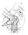
- a frame tube 4 is connected to the chassis of the front end on the bottom side of a front end 1.
- the frame tube consists of three square tubes arranged parallel to one another, which are connected to one another via the plates to be described later in the region of the swivel joint.
- an identical frame tube bundle 5 is fastened to the rear carriage 2, which frame tube consists of three tubes which are arranged in parallel and at a mutual distance from one another and are connected to one another via the further plates to be described later.
- a bellows 3 is arranged on the front end, which is attached to the rear end 2 in the same way.
- the top of the swivel joint is covered by a cover plate 13.
- the cover plate 13 is hinge-like and has a center or center offset hinge 17, which consists of a flexible material, such as. B. a plastic material. There is therefore no defined hinge axis, but an intermediate part is provided between the two fixed plate-like parts of the cover plate, which intermediate part acts as a hinge 17 and permits changes in length, resulting from torsional movements of the front and rear carriages.
- This part then absorbs the torsional movement and thus also the resulting changes in length relative to the front body 1 and the rear body 2.
- the front frame tube 4 extends with its end face 19 only shortly before the turntable 12 and that an upper plate 6 and a lower plate 7 are welded onto the top and the bottom of the respective frame tube 4.
- the slewing ring here consists of an inner and an outer race with balls arranged between them, the inner ring 20 being supported by an intermediate ring 21 on the underside of the upper plate 6.
- connection of the slewing ring 12 to the rear carriage is released in an analogous manner.
- an upper plate 8 and a lower plate 9 are welded onto the rear frame tube 5.
- the end face 22 of the frame tube 5 extends to just before the pitch axis 10, an upper plate 8 and a lower plate 9 being fastened in the same way to the frame tube 5, which plates accommodate the outer ring 23 of the rotating ring 12 between them.
- an intermediate ring 21 is provided, which is supported on the underside of the upper plate 8.
- the outer ring 23 is supported on the underside of the plate 8 by a padding 24.
- the slewing ring 12 can also be constructed differently, for example in such a way that the two rings 20, 23 are located near the top of the plates 6, 8 and that the rings 21 and the padding 24 are then separate Support at the bottom of plates 7 and 9.
- the padding 24 has a ring shape or is provided with local reinforcements.
- a slide plate 18 is arranged which carries the bellows carrier 14, which in turn is covered upwards by the cover plate 13.
- the essential advantage of a low overall height is achieved, because the frame tube 4 only has a height of 100 m and the previously mentioned plates 6, 7 are welded onto the frame tube 4 with an overall height of about 10 mm, which Plates 6, 7 form the receiving opening 15 between them in order to receive the entire slewing ring there.
- pitch axis 10 is structurally distant from the articulated shaft 11 of the slewing ring 12, which also results in a reduction in the overall height because the two components are not built up on one another, but are spatially separated from one another and therefore do not require any additional overall height.
- the supply lines 25 from the front end can be installed in the rear end between the upper and lower plates 6-9 and can be arranged in the area between the spaced frame tubes 4, 5 in order to optimally protect these supply lines against damage. It is thus avoided that, as is known, the supply lines have to be routed along the outside of the bus wall.
- the stabilizing cylinders 26 can also be guided in the space between the plates 6 - 9 and are therefore optimally protected against damage and likewise do not increase the overall height due to their installation in the frame tubes 4, 5.
- the plates 6 - 9 are designed so that they can also serve as a mechanical stop for the swivel joint.
Landscapes
- Engineering & Computer Science (AREA)
- Mechanical Engineering (AREA)
- Chemical & Material Sciences (AREA)
- Combustion & Propulsion (AREA)
- Transportation (AREA)
- Joints Allowing Movement (AREA)
- Tents Or Canopies (AREA)
- Body Structure For Vehicles (AREA)
Applications Claiming Priority (2)
| Application Number | Priority Date | Filing Date | Title |
|---|---|---|---|
| DE19904028649 DE4028649A1 (de) | 1990-09-10 | 1990-09-10 | Drehgelenk fuer niederflur-drehgelenk-omnibusse |
| DE4028649 | 1990-09-10 |
Publications (1)
| Publication Number | Publication Date |
|---|---|
| EP0475340A1 true EP0475340A1 (fr) | 1992-03-18 |
Family
ID=6413936
Family Applications (1)
| Application Number | Title | Priority Date | Filing Date |
|---|---|---|---|
| EP91115252A Ceased EP0475340A1 (fr) | 1990-09-10 | 1991-09-10 | Articulation pour autobus surbaissé et articulé |
Country Status (4)
| Country | Link |
|---|---|
| EP (1) | EP0475340A1 (fr) |
| CS (1) | CS277491A3 (fr) |
| DE (1) | DE4028649A1 (fr) |
| HU (1) | HU215299B (fr) |
Citations (4)
| Publication number | Priority date | Publication date | Assignee | Title |
|---|---|---|---|---|
| DE1136222B (de) * | 1956-05-15 | 1962-09-06 | Kaessbohrer Fahrzeug Karl | Strassengelenkwagenzug |
| EP0046484A2 (fr) * | 1980-08-23 | 1982-03-03 | Hymer-Leichtmetallbau | Véhicule articulé à plusieurs essieux |
| EP0340760A1 (fr) * | 1988-05-06 | 1989-11-08 | Waggon Union GmbH | Jonction articulée |
| DE3904756A1 (de) * | 1989-02-16 | 1990-08-23 | Hymer Leichtmetallbau | Drehgelenk fuer niederflur-gelenkomnibusse |
-
1990
- 1990-09-10 DE DE19904028649 patent/DE4028649A1/de not_active Withdrawn
-
1991
- 1991-09-09 CS CS912774A patent/CS277491A3/cs unknown
- 1991-09-10 EP EP91115252A patent/EP0475340A1/fr not_active Ceased
- 1991-09-10 HU HU912917A patent/HU215299B/hu not_active IP Right Cessation
Patent Citations (4)
| Publication number | Priority date | Publication date | Assignee | Title |
|---|---|---|---|---|
| DE1136222B (de) * | 1956-05-15 | 1962-09-06 | Kaessbohrer Fahrzeug Karl | Strassengelenkwagenzug |
| EP0046484A2 (fr) * | 1980-08-23 | 1982-03-03 | Hymer-Leichtmetallbau | Véhicule articulé à plusieurs essieux |
| EP0340760A1 (fr) * | 1988-05-06 | 1989-11-08 | Waggon Union GmbH | Jonction articulée |
| DE3904756A1 (de) * | 1989-02-16 | 1990-08-23 | Hymer Leichtmetallbau | Drehgelenk fuer niederflur-gelenkomnibusse |
Also Published As
| Publication number | Publication date |
|---|---|
| HUT61700A (en) | 1993-03-01 |
| DE4028649A1 (de) | 1992-03-12 |
| HU912917D0 (en) | 1992-01-28 |
| CS277491A3 (en) | 1992-03-18 |
| HU215299B (hu) | 1998-11-30 |
Similar Documents
| Publication | Publication Date | Title |
|---|---|---|
| DE2903795C2 (de) | Kopfabschluß einer Flugpassagierverladebrücke | |
| EP1741573B1 (fr) | Couverture du joint pour véhicules articulés | |
| DE2656622C2 (de) | Energieführungskette zur Aufnahme von Energieführungsleitungen | |
| EP1126986A1 (fr) | Dispositif de liaison entre deux pieces articulees d'un vehicule articule | |
| DE19501600C2 (de) | Stützanlage eines Verlegefahrzeuges, insbesondere eines Kettenfahrzeuges | |
| EP1712443B1 (fr) | Véhicule articulé à unités multiples, notamment véhicule ferroviaire. | |
| DE202013100563U1 (de) | Brücke zwischen zwei gelenkig miteinander verbundenen Fahrzeugteilen | |
| DE3033364C2 (de) | Anordnung einer Sattelkupplung auf einer Brückenkonstruktion eines Sattelschleppers | |
| DE4342402C2 (de) | Antriebs- und Riegelmechanismus für einen geradlinig ausfahrbaren Überrollbügel | |
| DE1951498B2 (de) | Korntank fuer maehdrescher | |
| DE2535131A1 (de) | Schiebeverdeck fuer lkw und anhaenger | |
| DE2450747C2 (de) | Zweiachsiges schienenfahrzeug mit einem verwindungsfaehigen untergestell | |
| DE60033900T2 (de) | Führung für eine bewegliche Abdeckung und bewegliche Abdeckung unter Verwendung einer solchen Führung | |
| DE4028649A1 (de) | Drehgelenk fuer niederflur-drehgelenk-omnibusse | |
| DE2612829C2 (de) | Geteilte Lenksäule | |
| EP0562092A1 (fr) | Couloir de communication flexible protege contre les intemperies et monte entre deux wagons de marchandises ayant des toits reglables en hauteur | |
| DE9108115U1 (de) | Zusammenschiebbares Verdeck für Fahrzeuge oder Fahrzeugaufbauten | |
| CH717246B1 (de) | Kuppelstange, insbesondere für ein Schienenfahrzeug. | |
| DE8429553U1 (de) | Kraftfahrzeug mit einem rahmen und einem aufbau | |
| EP0537670A1 (fr) | Soufflet pour connexion de véhicules articulés | |
| DE2218625C3 (de) | Klappbrücke zum Verbinden von Rampen | |
| CH630857A5 (en) | Displacement device for the fifth-wheel coupling on a semitrailer motor vehicle | |
| DE2833953C2 (de) | Vorrichtung zum Verringern des Luftwiderstandes eines Lastkraftwagens | |
| DE19914564B4 (de) | Gelenkverbindungsanordnung | |
| EP1473206B1 (fr) | Paroi d'extrémité pour wagon de chemin de fer |
Legal Events
| Date | Code | Title | Description |
|---|---|---|---|
| PUAI | Public reference made under article 153(3) epc to a published international application that has entered the european phase |
Free format text: ORIGINAL CODE: 0009012 |
|
| AK | Designated contracting states |
Kind code of ref document: A1 Designated state(s): AT CH DE FR GB IT LI |
|
| 17P | Request for examination filed |
Effective date: 19920908 |
|
| 17Q | First examination report despatched |
Effective date: 19930708 |
|
| RAP1 | Party data changed (applicant data changed or rights of an application transferred) |
Owner name: HYMER LEICHTMETALLBAU GMBH & CO. KG |
|
| STAA | Information on the status of an ep patent application or granted ep patent |
Free format text: STATUS: THE APPLICATION HAS BEEN REFUSED |
|
| 18R | Application refused |
Effective date: 19940812 |
|
| APAF | Appeal reference modified |
Free format text: ORIGINAL CODE: EPIDOSCREFNE |