EP0046736A2 - Stützvorrichtung für Zweiradfahrzeuge - Google Patents
Stützvorrichtung für Zweiradfahrzeuge Download PDFInfo
- Publication number
- EP0046736A2 EP0046736A2 EP81830118A EP81830118A EP0046736A2 EP 0046736 A2 EP0046736 A2 EP 0046736A2 EP 81830118 A EP81830118 A EP 81830118A EP 81830118 A EP81830118 A EP 81830118A EP 0046736 A2 EP0046736 A2 EP 0046736A2
- Authority
- EP
- European Patent Office
- Prior art keywords
- extremity
- rod
- rocker element
- support
- extreme
- Prior art date
- Legal status (The legal status is an assumption and is not a legal conclusion. Google has not performed a legal analysis and makes no representation as to the accuracy of the status listed.)
- Withdrawn
Links
- 230000000284 resting effect Effects 0.000 title claims abstract description 19
- 230000000694 effects Effects 0.000 claims abstract description 7
- 230000002093 peripheral effect Effects 0.000 claims description 4
- 230000010355 oscillation Effects 0.000 claims 1
- 238000010276 construction Methods 0.000 description 2
- 238000003780 insertion Methods 0.000 description 1
- 230000037431 insertion Effects 0.000 description 1
- 238000012986 modification Methods 0.000 description 1
- 230000004048 modification Effects 0.000 description 1
Images
Classifications
-
- B—PERFORMING OPERATIONS; TRANSPORTING
- B62—LAND VEHICLES FOR TRAVELLING OTHERWISE THAN ON RAILS
- B62H—CYCLE STANDS; SUPPORTS OR HOLDERS FOR PARKING OR STORING CYCLES; APPLIANCES PREVENTING OR INDICATING UNAUTHORIZED USE OR THEFT OF CYCLES; LOCKS INTEGRAL WITH CYCLES; DEVICES FOR LEARNING TO RIDE CYCLES
- B62H1/00—Supports or stands forming part of or attached to cycles
- B62H1/02—Articulated stands, e.g. in the shape of hinged arms
Definitions
- resting devices for two wheel vehicles particularly bicycles and motorcycles, commonly called “stands”
- stands consist essentially of a support that can be fastened to the frame of the vehicle in an integral fashion and sustains, by means of a pivot, a long rod.
- the said rod is movable from a first extreme position of minimum volume, in which it is kept almost horizontal at the side of the lower part of the frame of the vehicle, to a second extreme position for resting the vehicle, in which the said rod is virtually in a vertical position, slightly inclined towards the vehicle, and resting on the ground, in such a way as to constitute a reliable "prop" for the said vehicle.
- the object of the invention is to overcome the aforementioned difficulties by creating a resting device for two wheel vehicles which, in addition to being-particularly quick and easy to assemble, allows the user to bring about the return of the resting rod to its position of minimum volume in an easier way, through an external lever on which the sole of one of the shoes of the user can press down without any difficulty.
- the device forming the subject of the invention of the type that comprises & support that can be fastened to the frame of the vehicle in an integral fashion and sustains, by means of a pivot, a long rod movable from a first, almost horizontal, extreme position of minimum volume, to a second, almost vertical, extreme position for resting the vehicle, the said resting device being characterized by the fact that it comprises elastic means that exert on the said long rod, a torque pointed in the direction that goes from the said second to the said first extreme position of minimum volume and that, contemporaneously, come into contact with a first extremity of a rocker element, pivoted to the said support, causing a couple that tends to maintain the second extremity of the said rocker element in contact with the peripheral part of the said rod placed in the region of the said pivot, there being along the said part a member for locating the second extremity of the said rocker element, so as to maintain the said rod stably in the said second extreme resting position and overcome the said torque to which the said rod is subjecte
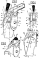
- the resting device in question comprises a support (1) that can be fastened, at (2), to the frame of a two wheel vehicle in an integral fashion and sustains, by means of a pivot, a long rod (3). More specifically, the rod (3) is able to rotate around a pin (4) carried transversely by a pair of opposite walls (5) and (6) of the support (1).
- the rod (3) is movable from a first, almost horizontal, extreme position of minimum volume (see Figure 3), to a second, almost vertical, extreme position for resting the vehicle (see Figures 1, 2 and 4).
- the resting device in question comprises, furthermore, elastic means, constituted by one single helical spring (7) wound around the pin (4).
- One extremity (7a) of the said spring (7) exerts an effect on the rod (3) and causes a torque pointed in the direction S that goes from the said second to the first extreme position of minimum volume.
- the other extremity (7b) of the spring (7) exerts an effect on a first extremity (8a) of a rocker element (8).
- each peripheral section (3a) is provided with a locator member, in the case in question a tooth (10), which serves to contrast the extremity (8b) of the rocker element (8), so as to maintain the rod (3) stably in the second extreme position, that is to say in its resting position, and to counteract the torque S to which the said rod (3) is subjected.
- the rocker element (8) is provided with a tail piece (11) that extends towards the outside of the support (1) and with which is integral an unlocking lever (12) operated from the outside through a top to bottom thrust in the direction of the arrow F.
- the operation of the lever (12) contrasts the couple S 1 applied to the rocker element (8), raises the extremity (8b) thereof from the tooth (10), and releases the rod (3) which is thus able to return from the second vertical position to the first position of minimum volume.
- the conformation of the rocker element (8) is, in plan view form, substantially a "U", where the extremity (8a) is constituted by an “ansa” (see Figures 1 and 3) formed on the stem that, in the case in question, extends along the pivoting axis (9), while the other stem coincides, in practice, with the extremity (8b).
- the tail piece (11) is shaped in the form of an "L” upside down, as can clearly be seen in Figures 1 and 3.
- the stem coinciding with the extremity (8b) protrudes transversely from the aforementioned walls (5) and (6), through a pair of slots (14) and (15), respectively, provided to allow the free ocillation of the extremity (8b) from a first extreme lowered position, corresponding to the said first extreme position of minimum volume of the rod (3), to a second extreme raised position adopted because of the operation of the unlocking lever (12).
- the other stem that is to say the one coinciding with the pivoting axis (9), protrudes from the wall (6), through a corresponding slot (16) provided to allow the extremity (8a) (shaped, as stated previously, with an "ansa”) to pass freely at the time of assembly.
- the said assembly operation is particularly simple since the rocker element is, in practice, inserted by its stems inside the aforementioned slots, and only subsequently is one extremity bent to' constitute the tail piece (11) that is shaped in the form of an "L" upside down.
- the rocker element (8) is located right inside the support (1), apart from the extremity thereof that constitutes the tail piece (11) (see Figure 4) which, this time, is bent prior to insertion.
- the rocker element (8) is pivoted at (9) to the support (1) at an intermediate point in between the stens that define the extremities (8a) and (8b).
- the rod (3) is provided with a projection (17) that serves to locate the extremity (7a) of the spring (7), while the extremity (7b) of the spring (7) exerts an effect on the extremity (8a) of the rocker element in, for example, the region of a small "ansa" (18).
Landscapes
- Engineering & Computer Science (AREA)
- Mechanical Engineering (AREA)
- Vehicle Body Suspensions (AREA)
- Lock And Its Accessories (AREA)
Applications Claiming Priority (2)
| Application Number | Priority Date | Filing Date | Title |
|---|---|---|---|
| IT494180U IT8004941V0 (it) | 1980-08-27 | 1980-08-27 | Dispositivo di appoggio per veicoli a due ruote |
| IT494180U | 1980-08-27 |
Publications (2)
| Publication Number | Publication Date |
|---|---|
| EP0046736A2 true EP0046736A2 (de) | 1982-03-03 |
| EP0046736A3 EP0046736A3 (de) | 1982-09-15 |
Family
ID=11116268
Family Applications (1)
| Application Number | Title | Priority Date | Filing Date |
|---|---|---|---|
| EP81830118A Withdrawn EP0046736A3 (de) | 1980-08-27 | 1981-07-15 | Stützvorrichtung für Zweiradfahrzeuge |
Country Status (2)
| Country | Link |
|---|---|
| EP (1) | EP0046736A3 (de) |
| IT (1) | IT8004941V0 (de) |
Cited By (4)
| Publication number | Priority date | Publication date | Assignee | Title |
|---|---|---|---|---|
| USD317143S (en) | 1988-06-29 | 1991-05-28 | Gebrueder Pletscher Ag | Kickstand for a bicycle or similar article |
| US6412805B1 (en) * | 2000-08-17 | 2002-07-02 | Bor Yueh Industries Co., Ltd. | Support leg frame of a bicycle |
| US7014203B2 (en) * | 2004-01-12 | 2006-03-21 | Dong-Shuei Liu | Kick stand assembly for a baby stroller |
| KR20190017194A (ko) * | 2017-08-10 | 2019-02-20 | 주식회사 에니텍시스 | 랜딩 장치 |
Family Cites Families (3)
| Publication number | Priority date | Publication date | Assignee | Title |
|---|---|---|---|---|
| GB784720A (en) * | 1955-03-19 | 1957-10-16 | Francis & Barnett Ltd | Improvements in cycle stands |
| US4119327A (en) * | 1977-07-13 | 1978-10-10 | Space-Age Control, Inc. | Lever for motorcycle center stand |
| FR2431415A1 (fr) * | 1978-07-21 | 1980-02-15 | Doncque Pierre | Dispositif de sustentation et d'immobilisation de vehicule, en particulier de motocyclette |
-
1980
- 1980-08-27 IT IT494180U patent/IT8004941V0/it unknown
-
1981
- 1981-07-15 EP EP81830118A patent/EP0046736A3/de not_active Withdrawn
Cited By (4)
| Publication number | Priority date | Publication date | Assignee | Title |
|---|---|---|---|---|
| USD317143S (en) | 1988-06-29 | 1991-05-28 | Gebrueder Pletscher Ag | Kickstand for a bicycle or similar article |
| US6412805B1 (en) * | 2000-08-17 | 2002-07-02 | Bor Yueh Industries Co., Ltd. | Support leg frame of a bicycle |
| US7014203B2 (en) * | 2004-01-12 | 2006-03-21 | Dong-Shuei Liu | Kick stand assembly for a baby stroller |
| KR20190017194A (ko) * | 2017-08-10 | 2019-02-20 | 주식회사 에니텍시스 | 랜딩 장치 |
Also Published As
| Publication number | Publication date |
|---|---|
| EP0046736A3 (de) | 1982-09-15 |
| IT8004941V0 (it) | 1980-08-27 |
Similar Documents
| Publication | Publication Date | Title |
|---|---|---|
| US4499676A (en) | Ski boot | |
| EP0248149B1 (de) | Schischuh | |
| US2452649A (en) | Slipper | |
| JPS6224081B2 (de) | ||
| US4575958A (en) | Ski boot | |
| US5899483A (en) | Device for retaining a boot on a gliding board, the device including a journalled dorsal support element | |
| EP0046736A2 (de) | Stützvorrichtung für Zweiradfahrzeuge | |
| EP0916272A2 (de) | Verriegelungsvorrichtung für von Sportschuhen, insbesondere für Skischuhe | |
| JPS6229066B2 (de) | ||
| KR100333282B1 (ko) | 자동차의 수동식 틸트장치 | |
| US4135728A (en) | Devices mounted on a ski | |
| ATE142852T1 (de) | Skischuh | |
| US3979132A (en) | Heel binding for cross country skis | |
| US4222584A (en) | Ski boot heel binding | |
| EP0546292A2 (de) | Skibremse | |
| JP2647633B2 (ja) | スキー靴 | |
| JPH0233808Y2 (de) | ||
| US4166635A (en) | Device for holding a boot to a sports article | |
| JPS605468Y2 (ja) | 押釦装置 | |
| JPH03221Y2 (de) | ||
| US4893830A (en) | Apparatus for the retention of a boot on a ski | |
| JPS6127578Y2 (de) | ||
| KR200328650Y1 (ko) | 조향핸들의 틸트 조정장치 | |
| JPS594517Y2 (ja) | プツシユ−スイツチにおけるロツク機構 | |
| JPH023994Y2 (de) |
Legal Events
| Date | Code | Title | Description |
|---|---|---|---|
| PUAI | Public reference made under article 153(3) epc to a published international application that has entered the european phase |
Free format text: ORIGINAL CODE: 0009012 |
|
| AK | Designated contracting states |
Designated state(s): BE DE FR GB |
|
| PUAL | Search report despatched |
Free format text: ORIGINAL CODE: 0009013 |
|
| AK | Designated contracting states |
Designated state(s): BE DE FR GB |
|
| 17P | Request for examination filed |
Effective date: 19820902 |
|
| STAA | Information on the status of an ep patent application or granted ep patent |
Free format text: STATUS: THE APPLICATION IS DEEMED TO BE WITHDRAWN |
|
| 18D | Application deemed to be withdrawn |
Effective date: 19840202 |
|
| RIN1 | Information on inventor provided before grant (corrected) |
Inventor name: MONTANELLI, GUIDO |