EP0046824A2 - Interrupteur à gaz comprimé - Google Patents
Interrupteur à gaz comprimé Download PDFInfo
- Publication number
- EP0046824A2 EP0046824A2 EP80108160A EP80108160A EP0046824A2 EP 0046824 A2 EP0046824 A2 EP 0046824A2 EP 80108160 A EP80108160 A EP 80108160A EP 80108160 A EP80108160 A EP 80108160A EP 0046824 A2 EP0046824 A2 EP 0046824A2
- Authority
- EP
- European Patent Office
- Prior art keywords
- switch
- space
- contact piece
- arc
- extinguishing
- Prior art date
- Legal status (The legal status is an assumption and is not a legal conclusion. Google has not performed a legal analysis and makes no representation as to the accuracy of the status listed.)
- Granted
Links
- 238000005192 partition Methods 0.000 claims abstract description 30
- 238000003860 storage Methods 0.000 claims abstract description 15
- 230000000171 quenching effect Effects 0.000 claims description 18
- 238000010791 quenching Methods 0.000 claims description 17
- 230000003628 erosive effect Effects 0.000 claims description 6
- OKTJSMMVPCPJKN-UHFFFAOYSA-N Carbon Chemical compound [C] OKTJSMMVPCPJKN-UHFFFAOYSA-N 0.000 claims description 3
- 229910002804 graphite Inorganic materials 0.000 claims description 3
- 239000010439 graphite Substances 0.000 claims description 3
- 238000000926 separation method Methods 0.000 claims 1
- 238000011144 upstream manufacturing Methods 0.000 claims 1
- 239000011810 insulating material Substances 0.000 abstract description 3
- VQKWAUROYFTROF-UHFFFAOYSA-N arc-31 Chemical compound O=C1N(CCN(C)C)C2=C3C=C4OCOC4=CC3=NN=C2C2=C1C=C(OC)C(OC)=C2 VQKWAUROYFTROF-UHFFFAOYSA-N 0.000 description 3
- 229910018503 SF6 Inorganic materials 0.000 description 1
- UUAGAQFQZIEFAH-UHFFFAOYSA-N chlorotrifluoroethylene Chemical group FC(F)=C(F)Cl UUAGAQFQZIEFAH-UHFFFAOYSA-N 0.000 description 1
- 239000004020 conductor Substances 0.000 description 1
- 238000010438 heat treatment Methods 0.000 description 1
- 238000002955 isolation Methods 0.000 description 1
- 238000004519 manufacturing process Methods 0.000 description 1
- 239000000463 material Substances 0.000 description 1
- 229920000642 polymer Polymers 0.000 description 1
- -1 polytetrafluoroethylene Polymers 0.000 description 1
- 229920001343 polytetrafluoroethylene Polymers 0.000 description 1
- 239000004810 polytetrafluoroethylene Substances 0.000 description 1
- SFZCNBIFKDRMGX-UHFFFAOYSA-N sulfur hexafluoride Chemical compound FS(F)(F)(F)(F)F SFZCNBIFKDRMGX-UHFFFAOYSA-N 0.000 description 1
- 229960000909 sulfur hexafluoride Drugs 0.000 description 1
Images
Classifications
-
- H—ELECTRICITY
- H01—ELECTRIC ELEMENTS
- H01H—ELECTRIC SWITCHES; RELAYS; SELECTORS; EMERGENCY PROTECTIVE DEVICES
- H01H33/00—High-tension or heavy-current switches with arc-extinguishing or arc-preventing means
- H01H33/70—Switches with separate means for directing, obtaining, or increasing flow of arc-extinguishing fluid
- H01H33/98—Switches with separate means for directing, obtaining, or increasing flow of arc-extinguishing fluid the flow of arc-extinguishing fluid being initiated by an auxiliary arc or a section of the arc, without any moving parts for producing or increasing the flow
Definitions
- the present invention relates to a gas pressure switch, with a fixed contact piece, with a rod-shaped movable contact piece which can be brought axially into engagement with the fixed contact piece, and with a housing whose interior is inserted into the housing between an erosion electrode located in front of the fixed contact piece and one which is spaced apart in the switch-off direction for the movable contact piece having a pressure opening opening extending arc pressure chamber, in a between the partition wall and a spaced therefrom in the switch-off direction and inserted into the housing extinguishing chamber and in an existing on the side facing away from the extinguishing space of the intermediate wall with the extinguishing space in the course of Switch-off stroke is subdivided via an expansion space which comes into gas connection through the channel which is released by the movable contact piece, the arc pressure space and the quenching space being connected to one another via a large one Communicate the volume of the space than the storage space having the arc pressure space and provided with at least one flow deflecting body.
- a gas pressure switch of the type described is known.
- the purpose of the open channel provided in this known compressed gas switch between the arcing pressure chamber and the quenching space via the storage space is that the pressure generated in the arcing pressure space by the auxiliary arc drives fresh gas into the quenching space from the storage space, thereby making it easier to extinguish the main arc in the quenching space.
- a second channel is connected in parallel to this open channel in the course of the switch-off stroke, namely after the movable contact piece has been installed in the partition Has left passage opening between the arc pressure chamber and the quenching room.
- This direct connection between the arc pressure chamber and the extinguishing room causes on the one hand that a decrease in pressure occurs in the arc pressure room, which results in a reduction in the fresh gas flow from the storage space into the extinguishing room and, on the other hand, that hot gas ionized into the extinguishing room through the direct channel which has become free flows, which makes it difficult to extinguish the main arc.
- the quenching properties of this known switch depend on the ratio of the flow resistances from the arc pressure chamber to the quenching chamber on the one hand via the storage space and on the other hand via the passage opening provided for the movable contact piece in the partition.
- a further pressure gas switch with an arc pressure chamber and an extinguishing chamber is known, but in which a storage space provided with at least one flow deflecting body is missing.
- the arc pressure chamber is in direct connection with the extinguishing chamber which is closed off from an expansion chamber with a pressure relief valve attached to the fixed contact piece.
- the movable contact piece is formed over part of its length by an insulating piece. This isolation piece is bridged in the switch-on position by an electrically conductive sleeve arranged between the arc pressure chamber and the quenching chamber.
- the part of the movable contact piece attached to the insulating piece is pulled out of the fixed contact piece, after which the arc quenching begins when the relatively hot and ionized gas flows out of the quenching space via the pressure relief valve into the expansion space.
- the disadvantage of this gas pressure switch is that it is difficult to find a material for the insulating piece in the movable contact piece that can withstand the electrical, thermal and mechanical stresses.
- the pressure relief valve that closes the extinguishing chamber is a very sensitive element that is endangered particularly when relatively high short-circuit currents are switched off or at least its response values do not remain constant. This gas pressure switch is also unsuitable for carrying relatively high operating currents and for interrupting relatively high short-circuit currents.
- a spring-loaded trailing pin is provided between the movable and the fixed contact piece.
- the trailing pin separates first from the fixed contact piece, creating a pressure-generating auxiliary arc.
- the movable contact piece separates from the trailing pin in the extinguishing area.
- the pressure generated by the auxiliary arc and also by the main arc in the quenching space drives quenching gas through a nozzle released by the movable switching element in the course of the switch-off stroke.
- This pressure gas switch is also not suitable for carrying relatively high operating currents, because the contact points between the fixed contact piece and the trailing pin and between the trailing pin and the fixed contact piece are also arcing points, which means that the contact resistance of these contact points can become too high without being noticed during operation. The heating of these contact points can exceed the permissible limits unnoticed at high operating currents.
- the object of the present invention is to design a gas pressure switch of the type mentioned at the outset for guiding relatively high operating currents and for interrupting relatively high short-circuit currents.
- the fixed contact piece which is enclosed by the latter in the course of the switch-on stroke against the action of a spring in its initial position by the movable contact piece, is axially displaceable and in the course of the switch-off stroke the movable contact piece is left until it leaves the partition and then the is connected between the arc pressure chamber and the quenching space in the partition closing trailing insulating piston and that the arc pressure chamber and the Edge areas facing the extinguishing space of the passage opening in the partition are electrically conductively connected to one another.
- the trailing insulating piston can advantageously be hollow.
- the insulating piston is pressure-compensated and does not have to have a spring that would have to counteract the pressure in the extinguishing chamber.
- the extinguishing chamber can communicate with an additional expansion space arranged on the side of the trailing insulating piston facing away from the extinguishing chamber in the course of the switch-off stroke after the movable switching element has been separated from the trailing insulating piston via the hollow trailing insulating piston. This measure allows the expansion space to be subdivided or enlarged by an additional space.
- the edge region of the passage opening in the partition wall can consist of an electrically conductive ring inserted into the partition wall. This enables economically advantageous manufacturing processes for the partition.
- the ring can advantageously consist of graphite.
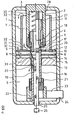
- the pressure gas switch shown has an extinguishing gas, e.g. Sulfur hexafluoride, filled., 1 sealed from the outside from an insulating material.
- a fixed contact piece 2 is arranged in the housing 1, which is led out through the upper end wall 3 of the housing and is anchored in this end wall.
- the fixed contact piece 2 has a ring of resilient contact fingers 4, which are preceded by an erosion electrode 5.
- the interior of the housing 1 is divided into an arc pressure space 6, a storage space 7, an extinguishing space 8 and an expansion space 9.
- the arcing pressure chamber 6 lies between the erosion electrode 5 and a partition 10 fastened in the switching direction 1 at a distance from it.
- the storage space 7 is delimited by the fixed contact piece 2, by the housing 1 and the partition wall 10 and has a fixed contact piece 2 coaxially at a distance surrounding, attached to the partition 10, open at the top, cylindrical flow deflector 11.
- the storage space 7 is on the one hand directly connected to the arc pressure space 6 and on the other hand to the extinguishing space 8 via a plurality of openings 12 provided radially behind the flow deflecting body 11 in the partition 10.
- the extinguishing space 8 is separated from the expansion space 9 by an electrically insulating intermediate wall 13 fastened in the housing 1 and divided by an insulating disk 15 provided with openings 14.
- a movable, tubular contact piece 16 extends - in the switch-on position shown in the right half of the figure - through the passages formed in the intermediate wall 13 and in the insulating disk 15, through the passage opening provided in the partition wall 10 tion 17 and engages with its free end 18 in the ring of contact fingers 4.
- the movable tubular contact piece 16 is closed inside by an intermediate floor 19. Openings 20 are provided in the tube wall between the intermediate floor 19 and the free end 18 of the movable contact piece 16, which allow the gas connection between the extinguishing space 8 and the expansion space 9 in the course of the switch-off stroke.
- the lower end of the movable contact piece 16 is guided by a set of sliding contacts 21, which in turn are fastened to a ring 22 which forms the inner end of a connecting conductor 23. This is tightly attached at 24 in the housing 1 and led out laterally from this.
- the lower end of the movable contact piece 16 is coupled via an insulating switching rod 25 to a drive 26, only shown schematically, with which the movable contact piece 16 is axially displaceable.
- An axially displaceable trailing insulating piston 27 is guided in the fixed contact piece 2. It can be made from polytetrafluoroethylene, from a polymer of trifluorochloroethylene or from another suitable electrical insulating material.
- This trailing insulating piston 27 is moved in the course of the switch-on stroke against the action of a spring 28 into its starting position by the movable contact piece 16 and in the course of the switch-off stroke the movable contact piece 16 follow until the partition 10 is released under the action of the spring 28.
- the trailing insulating piston 27 stops and closes the passage opening 17 located between the arc pressure chamber 6 and the extinguishing chamber 8 in the partition 10.
- an electrically conductive ring 29 is inserted into the partition 10. This ring 29 delimits the passage opening 17 in the partition 10 and is made of graphite.
- an additional expansion space 30 is accommodated, which comes into gas connection with the extinguishing space 8 via the hollow trailing insulating piston 27 in the course of the switch-off stroke.
- the trailing insulating piston 27 follows the movement of the movable contact piece 16 under the action of the spring 28.
- An auxiliary arc 31 does not ignite in the arcing pressure chamber 6 until the upper end 18 of the movable contact piece 16 has the contact fingers 4 and the erosion electrode 5 has left.
- This arc is the "pressure build-up arc" that causes an increase in pressure in the arc pressure space.
- the upper end 18 of the movable contact piece 16 leaves the passage opening 17 in the partition 10.
- the trailing insulating piston 27 dips into this passage opening 17 with its tip, stops and closes it.
- the auxiliary arc 31 meanwhile continues to burn in the arc pressure chamber 6 between the erosion electrode 5 and the ring 29.
Landscapes
- Circuit Breakers (AREA)
- Percussion Or Vibration Massage (AREA)
- Glass Compositions (AREA)
- Vehicle Body Suspensions (AREA)
- Arc-Extinguishing Devices That Are Switches (AREA)
Priority Applications (1)
| Application Number | Priority Date | Filing Date | Title |
|---|---|---|---|
| AT80108160T ATE8440T1 (de) | 1980-09-01 | 1980-12-23 | Druckgasschalter. |
Applications Claiming Priority (2)
| Application Number | Priority Date | Filing Date | Title |
|---|---|---|---|
| CH6564/80 | 1980-09-01 | ||
| CH656480 | 1980-09-01 |
Publications (3)
| Publication Number | Publication Date |
|---|---|
| EP0046824A2 true EP0046824A2 (fr) | 1982-03-10 |
| EP0046824A3 EP0046824A3 (en) | 1982-03-17 |
| EP0046824B1 EP0046824B1 (fr) | 1984-07-11 |
Family
ID=4311582
Family Applications (1)
| Application Number | Title | Priority Date | Filing Date |
|---|---|---|---|
| EP80108160A Expired EP0046824B1 (fr) | 1980-09-01 | 1980-12-23 | Interrupteur à gaz comprimé |
Country Status (4)
| Country | Link |
|---|---|
| US (1) | US4395607A (fr) |
| EP (1) | EP0046824B1 (fr) |
| AT (1) | ATE8440T1 (fr) |
| DE (1) | DE3068564D1 (fr) |
Cited By (3)
| Publication number | Priority date | Publication date | Assignee | Title |
|---|---|---|---|---|
| FR2542918A1 (fr) * | 1983-03-15 | 1984-09-21 | Merlin Gerin | Interrupteur a arc tournant a circulation des gaz ionises |
| DE3440212A1 (de) * | 1984-10-10 | 1986-04-17 | BBC Aktiengesellschaft Brown, Boveri & Cie., Baden, Aargau | Druckgasschalter |
| CN111128595A (zh) * | 2019-12-31 | 2020-05-08 | 宁波军鸽防务科技有限公司 | 控制开关 |
Families Citing this family (1)
| Publication number | Priority date | Publication date | Assignee | Title |
|---|---|---|---|---|
| EP3504726B1 (fr) * | 2016-08-26 | 2020-12-02 | ABB Power Grids Switzerland AG | Interrupteur et procédé de séparation des contacts d'un interrupteur |
Family Cites Families (8)
| Publication number | Priority date | Publication date | Assignee | Title |
|---|---|---|---|---|
| CH250184A (de) * | 1943-03-06 | 1947-08-15 | Lange Emil | Schalter mit Löschung des Lichtbogens durch einen vom Lichtbogen selbst erzeugten Drucklöschmittelstrom. |
| US2671147A (en) * | 1950-05-18 | 1954-03-02 | Westinghouse Electric Corp | Circuit interrupter |
| US2671144A (en) * | 1950-05-18 | 1954-03-02 | Westinghouse Electric Corp | Circuit interrupter |
| DE2316008B2 (de) * | 1973-03-30 | 1978-03-30 | Siemens Ag, 1000 Berlin Und 8000 Muenchen | Anordnung zur Löschung eines rotierenden elektrischen Wechselstromlichtbogens |
| FR2369673A1 (fr) * | 1976-10-28 | 1978-05-26 | Cem Comp Electro Mec | Appareil electrique de coupure a auto-soufflage de l'arc electrique de coupure par un gaz |
| DE7728194U1 (de) * | 1976-10-20 | 1978-09-28 | Bbc Ag Brown, Boveri & Cie, Baden, Aargau (Schweiz) | Gasschalter mit Eigenlöschung |
| FR2373141A1 (fr) * | 1976-12-06 | 1978-06-30 | Cem Comp Electro Mec | Appareil electrique de coupure a haute tension, notamment un disjoncteur a autosoufflage de l'arc de coupure par un gaz |
| CH650359A5 (en) * | 1980-01-25 | 1985-07-15 | Sprecher & Schuh Ag | Gas-blast circuit breaker |
-
1980
- 1980-12-23 EP EP80108160A patent/EP0046824B1/fr not_active Expired
- 1980-12-23 AT AT80108160T patent/ATE8440T1/de not_active IP Right Cessation
- 1980-12-23 DE DE8080108160T patent/DE3068564D1/de not_active Expired
-
1981
- 1981-08-31 US US06/298,045 patent/US4395607A/en not_active Expired - Fee Related
Cited By (3)
| Publication number | Priority date | Publication date | Assignee | Title |
|---|---|---|---|---|
| FR2542918A1 (fr) * | 1983-03-15 | 1984-09-21 | Merlin Gerin | Interrupteur a arc tournant a circulation des gaz ionises |
| DE3440212A1 (de) * | 1984-10-10 | 1986-04-17 | BBC Aktiengesellschaft Brown, Boveri & Cie., Baden, Aargau | Druckgasschalter |
| CN111128595A (zh) * | 2019-12-31 | 2020-05-08 | 宁波军鸽防务科技有限公司 | 控制开关 |
Also Published As
| Publication number | Publication date |
|---|---|
| DE3068564D1 (en) | 1984-08-16 |
| EP0046824A3 (en) | 1982-03-17 |
| EP0046824B1 (fr) | 1984-07-11 |
| US4395607A (en) | 1983-07-26 |
| ATE8440T1 (de) | 1984-07-15 |
Similar Documents
| Publication | Publication Date | Title |
|---|---|---|
| EP0951039B1 (fr) | Sectionneur de puissance | |
| EP2126947B1 (fr) | Disjoncteur à gaz comprimé avec une aperture radiale du passage | |
| DE2209287C3 (de) | Elektrischer Druckgasschalter | |
| DE2750762C2 (fr) | ||
| DE2039240A1 (de) | Druckgasschalter,insbesondere mit Selbstbeblasung | |
| DE3300816C2 (de) | Druckgasleistungsschalter | |
| EP0067460A1 (fr) | Disjoncteur de puissance pour haute tension | |
| DE2812945C2 (de) | Druckgasschalter | |
| DE2030605B2 (de) | Elektrischer Druckgasschalter mit einer Blaseinrichtung zur Erzeugung einer Löschgasströmung | |
| DE2812947C2 (de) | Druckgas-Leistungsschalter | |
| DE2545479A1 (de) | Hochspannungs-schaltgeraet | |
| DE1233047B (de) | Elektrischer Schalter mit Lichtbogenloeschung durch Druckgas | |
| EP0046824B1 (fr) | Interrupteur à gaz comprimé | |
| DE2741022C2 (de) | Elektrischer Druckgasschalter | |
| DE3009165C2 (fr) | ||
| EP0035581B1 (fr) | Disjoncteur à gaz comprimé | |
| EP0000501B1 (fr) | Disjoncteur à gaz comprimé | |
| DE2627948C2 (de) | Autopneumatischer Druckgasschalter | |
| DE2853201C2 (fr) | ||
| DE963442C (de) | Druckgasschalter | |
| EP1225610B1 (fr) | Agencement de contacts d'arc pour disjoncteur | |
| DE725073C (de) | Druckgasschalter mit zwei in Reihe liegenden Kontaktstellen | |
| EP0664553B1 (fr) | Disjoncteur de puissance haute tension à chambre d'échauffement | |
| DE808056C (de) | Elektrischer Hochspannungsschalter | |
| EP1837889A2 (fr) | Ensemble interrupteur avec une résistance de démarrage |
Legal Events
| Date | Code | Title | Description |
|---|---|---|---|
| PUAI | Public reference made under article 153(3) epc to a published international application that has entered the european phase |
Free format text: ORIGINAL CODE: 0009012 |
|
| PUAL | Search report despatched |
Free format text: ORIGINAL CODE: 0009013 |
|
| AK | Designated contracting states |
Designated state(s): AT BE CH DE FR GB IT LI LU NL SE |
|
| AK | Designated contracting states |
Designated state(s): AT BE CH DE FR GB IT LI LU NL SE |
|
| 17P | Request for examination filed |
Effective date: 19820322 |
|
| GRAA | (expected) grant |
Free format text: ORIGINAL CODE: 0009210 |
|
| AK | Designated contracting states |
Designated state(s): AT BE CH DE FR GB IT LI LU NL SE |
|
| PG25 | Lapsed in a contracting state [announced via postgrant information from national office to epo] |
Ref country code: SE Effective date: 19840711 Ref country code: NL Effective date: 19840711 Ref country code: IT Free format text: LAPSE BECAUSE OF FAILURE TO SUBMIT A TRANSLATION OF THE DESCRIPTION OR TO PAY THE FEE WITHIN THE PRESCRIBED TIME-LIMIT;WARNING: LAPSES OF ITALIAN PATENTS WITH EFFECTIVE DATE BEFORE 2007 MAY HAVE OCCURRED AT ANY TIME BEFORE 2007. THE CORRECT EFFECTIVE DATE MAY BE DIFFERENT FROM THE ONE RECORDED. Effective date: 19840711 Ref country code: FR Free format text: THE PATENT HAS BEEN ANNULLED BY A DECISION OF A NATIONAL AUTHORITY Effective date: 19840711 Ref country code: BE Effective date: 19840711 |
|
| REF | Corresponds to: |
Ref document number: 8440 Country of ref document: AT Date of ref document: 19840715 Kind code of ref document: T |
|
| REF | Corresponds to: |
Ref document number: 3068564 Country of ref document: DE Date of ref document: 19840816 |
|
| PGFP | Annual fee paid to national office [announced via postgrant information from national office to epo] |
Ref country code: CH Payment date: 19841203 Year of fee payment: 5 |
|
| PGFP | Annual fee paid to national office [announced via postgrant information from national office to epo] |
Ref country code: DE Payment date: 19841206 Year of fee payment: 5 |
|
| PG25 | Lapsed in a contracting state [announced via postgrant information from national office to epo] |
Ref country code: LU Free format text: LAPSE BECAUSE OF NON-PAYMENT OF DUE FEES Effective date: 19841231 |
|
| NLV1 | Nl: lapsed or annulled due to failure to fulfill the requirements of art. 29p and 29m of the patents act | ||
| PLBE | No opposition filed within time limit |
Free format text: ORIGINAL CODE: 0009261 |
|
| STAA | Information on the status of an ep patent application or granted ep patent |
Free format text: STATUS: NO OPPOSITION FILED WITHIN TIME LIMIT |
|
| 26N | No opposition filed | ||
| GBPC | Gb: european patent ceased through non-payment of renewal fee | ||
| EN | Fr: translation not filed | ||
| PGFP | Annual fee paid to national office [announced via postgrant information from national office to epo] |
Ref country code: AT Payment date: 19851126 Year of fee payment: 6 |
|
| PG25 | Lapsed in a contracting state [announced via postgrant information from national office to epo] |
Ref country code: AT Effective date: 19861223 |
|
| PG25 | Lapsed in a contracting state [announced via postgrant information from national office to epo] |
Ref country code: LI Effective date: 19861231 Ref country code: CH Effective date: 19861231 |
|
| REG | Reference to a national code |
Ref country code: CH Ref legal event code: PL |
|
| PG25 | Lapsed in a contracting state [announced via postgrant information from national office to epo] |
Ref country code: DE Effective date: 19870901 |
|
| PG25 | Lapsed in a contracting state [announced via postgrant information from national office to epo] |
Ref country code: GB Effective date: 19881118 |