EP0047135A2 - Appareil et procédé de flottation dans un champ centrifuge - Google Patents
Appareil et procédé de flottation dans un champ centrifuge Download PDFInfo
- Publication number
- EP0047135A2 EP0047135A2 EP81303915A EP81303915A EP0047135A2 EP 0047135 A2 EP0047135 A2 EP 0047135A2 EP 81303915 A EP81303915 A EP 81303915A EP 81303915 A EP81303915 A EP 81303915A EP 0047135 A2 EP0047135 A2 EP 0047135A2
- Authority
- EP
- European Patent Office
- Prior art keywords
- vessel
- chamber
- gas
- flotation
- vortex
- Prior art date
- Legal status (The legal status is an assumption and is not a legal conclusion. Google has not performed a legal analysis and makes no representation as to the accuracy of the status listed.)
- Withdrawn
Links
Images

Classifications
-
- B—PERFORMING OPERATIONS; TRANSPORTING
- B03—SEPARATION OF SOLID MATERIALS USING LIQUIDS OR USING PNEUMATIC TABLES OR JIGS; MAGNETIC OR ELECTROSTATIC SEPARATION OF SOLID MATERIALS FROM SOLID MATERIALS OR FLUIDS; SEPARATION BY HIGH-VOLTAGE ELECTRIC FIELDS
- B03D—FLOTATION; DIFFERENTIAL SEDIMENTATION
- B03D1/00—Flotation
- B03D1/14—Flotation machines
- B03D1/1418—Flotation machines using centrifugal forces
- B03D1/1425—Flotation machines using centrifugal forces air-sparged hydrocyclones
-
- B—PERFORMING OPERATIONS; TRANSPORTING
- B03—SEPARATION OF SOLID MATERIALS USING LIQUIDS OR USING PNEUMATIC TABLES OR JIGS; MAGNETIC OR ELECTROSTATIC SEPARATION OF SOLID MATERIALS FROM SOLID MATERIALS OR FLUIDS; SEPARATION BY HIGH-VOLTAGE ELECTRIC FIELDS
- B03D—FLOTATION; DIFFERENTIAL SEDIMENTATION
- B03D1/00—Flotation
- B03D1/14—Flotation machines
- B03D1/1493—Flotation machines with means for establishing a specified flow pattern
-
- B—PERFORMING OPERATIONS; TRANSPORTING
- B04—CENTRIFUGAL APPARATUS OR MACHINES FOR CARRYING-OUT PHYSICAL OR CHEMICAL PROCESSES
- B04C—APPARATUS USING FREE VORTEX FLOW, e.g. CYCLONES
- B04C5/00—Apparatus in which the axial direction of the vortex is reversed
- B04C5/08—Vortex chamber constructions
- B04C5/10—Vortex chamber constructions with perforated walls
-
- B—PERFORMING OPERATIONS; TRANSPORTING
- B04—CENTRIFUGAL APPARATUS OR MACHINES FOR CARRYING-OUT PHYSICAL OR CHEMICAL PROCESSES
- B04C—APPARATUS USING FREE VORTEX FLOW, e.g. CYCLONES
- B04C7/00—Apparatus not provided for in group B04C1/00, B04C3/00, or B04C5/00; Multiple arrangements not provided for in one of the groups B04C1/00, B04C3/00, or B04C5/00; Combinations of apparatus covered by two or more of the groups B04C1/00, B04C3/00, or B04C5/00
-
- B—PERFORMING OPERATIONS; TRANSPORTING
- B04—CENTRIFUGAL APPARATUS OR MACHINES FOR CARRYING-OUT PHYSICAL OR CHEMICAL PROCESSES
- B04C—APPARATUS USING FREE VORTEX FLOW, e.g. CYCLONES
- B04C9/00—Combinations with other devices, e.g. fans, expansion chambers, diffusors, water locks
-
- B—PERFORMING OPERATIONS; TRANSPORTING
- B03—SEPARATION OF SOLID MATERIALS USING LIQUIDS OR USING PNEUMATIC TABLES OR JIGS; MAGNETIC OR ELECTROSTATIC SEPARATION OF SOLID MATERIALS FROM SOLID MATERIALS OR FLUIDS; SEPARATION BY HIGH-VOLTAGE ELECTRIC FIELDS
- B03D—FLOTATION; DIFFERENTIAL SEDIMENTATION
- B03D1/00—Flotation
- B03D1/14—Flotation machines
- B03D1/1431—Dissolved air flotation machines
Definitions
- This invention relates to a novel flotation apparatus and method and, more particularly, to a novel flotation apparatus and method for achieving flotation in a centrifugal field.
- Flotation is a process in which the apparent density of one particulate constituent of a suspension of divided particles is reduced by the adhesion of gas bubbles to that respective particulate constituent.
- the buoyancy of the bubble/particle aggregate is such that it rises to the surface and is thereby separated by gravity from the remaining particulate constituents, which do not attract air, and which, therefore, remain suspended in the liquid phase.
- the preferred method for removing the floated material is to form a froth, or foam, to collect the bubble/particle aggregates.
- the froth with collected bubble/particle aggregates is removed from the top of the suspension. This process is called froth flotation and is conducted as a continuous process in equipment called flotation cells.
- froth flotation is favored by copious quantities of small, one to two millimeter bubbles.
- the success of flotation depends on controlling conditions in the suspension so that air is selectively retained by one constituent and rejected by the others.
- the pulp must be treated by the addition of small amounts of known chemicals which render one constituent floatable with respect to the remaining constituents.
- a complete flotation process is conducted in several steps: (1) the feed is ground, usually to a size less than about 28 mesh; (2) a slurry containing about 5 to 40 percent solids in water is prepared; (3) the necessary chemicals are added and sufficient agitation and time provided to distribute the chemicals on the surface of the particles to be floated; (4) the treated slurry is aerated in a flotation cell by agitation in the presence of a stream of air or by blowing air in fine streams through the pulp; and (5) the aerated particles in the froth are withdrawn from the top of the cell as a froth product (frequently as the concentrate) and the remaining solids and water are discharged from the bottom of the cell (frequently as the tailing product).
- frothers Chemicals useful in creating the froth phase for the flotation process are commonly referred to as frothers.
- frothers Chemicals useful in creating the froth phase for the flotation process are commonly referred to as frothers.
- the most common frothers are short chain alcohols such as methyl isobutyl carbinol, pine oil, cresylic acid, and the like.
- the criteria for a good frother revolves around the criteria of solubility, toughness, texture, froth breakage, and non- collecting techniques. In practical flotation tests, the size, number, and stability of the bubbles during flotation may be optimized at given frother concentrations.
- Induction time can be defined as the time taken for a bubble to form a three-phase contact at a solid surface after initial bubble/particle collision. Alternatively, it can be regarded as the time taken after collision for the liquid film between a particle and bubble to thin to its rupture thickness. Induction times which are characteristics of good flotation conditions are known to be of the order of 10 milliseconds.
- flotation techniques include the addition of an emulsion of oil.
- the separation of coal is greatly assisted by the addition of about three to five percent or more oil to enhance the formation of oil droplet/coal particle aggregates.
- a slurry of ground coal is flocculated with the oil and the flocs which float are separated from the refuse material by skimming from the surface. While this technique does not utilize air bubbles for flotation, the adaptation of this system to froth flotation has been used both for coal and a variety of ores such as manganese dioxide and ilmenite (an oxide mineral of iron and titanium). In this latter process, a collector and fuel oil are added to the ore slurry, often with an emulsifier.
- the conditions of the process are adjusted so that when the pulp is aerated, the dispersed oil/particle suspension inverts from that of oil-in-water in the pulp to one of water-in-oil in the froth.
- This process therefore, occupies a middle position between froth flotation and the foregoing oil flotation process.
- the quantity of oil used is usually much lower than that used for the bulk oil or spherical agglomeration process, generally only one to several pounds of oil per ton of ore processed.
- the modifications of conventional froth flotation are referred to in the art as emulsion or oil flotation.
- flotation Since for effective aeration in the particles should be small and the original density of the floated material is not too critical, flotation can be applied where conventional gravity separation techniques fail. Indeed, so successful and versatile has flotation become that it has supplanted the older gravity separation methods in a number of separation problems.
- flotation was used to separate sulphide ores of copper, lead and zinc from associated gangue mineral particles but is also used for concentrating nonsulphide ores, for cleaning coal, for separating salts from their mother liquors, and for recovering elements such as sulphur and graphite.
- the cyclonic separator or hydrocyclone is a piece of equipment which utilizes fluid pressure energy to create rotational fluid motion.
- This rotational motion causes relative movement of particles suspended in the fluid thus permitting separation of particles, one from another or from the fluid.
- the rotational fluid motion is produced by tangential injection of fluid under pressure into a vessel;
- the vessel at that point of entry for the fluid is usually cylindrical and can remain cylindrical over its entire length though it is more usual for it to become conical.
- the hydrocyclone is used successfully for dewatering a suspension or for making a size separation (classifying hydrocyclone). However, equally important is its use as a gravity separator.
- Hydrocyclones have been used extensively as gravity separators in coal preparation plants and design features have been established for such applications which emphasize the difference in particle gravity rather than the differences in particle size.
- Two general categories of hydrocyclones used for gravity separation can be distinguished by their design features particularly with respect to their feed and discharge ports and, to a lesser extent, by the presence or absence of a conical section.
- the first type of hydrocyclone generally has three inlet and outlet ports and consists of a cylindrical vessel ranging, as found in industry, from 2 to 24 inches in diameter with a conical or bowl-shaped bottom. Variations exist in the shape, dimensions, bottom design, vortex finder, etc. Choice of the various parameters of the cyclone depend upon the size of the particles to be treated and the efficiency desired. Thus, the major operating variables of the hydrocyclone are: the vertical clearance between the lower orifice edge of the vortex finder and the cyclone bottom; vortex finder diameter; apex diameter; concentration of feed solids; and inlet pressure.
- the particle/water slurry is introduced tangentially and under pressure into the cylindrical section of the cyclone where centrifugal force acts on the particles in proportion to their mass.
- the centrifugal force acting on the particles increases with decreasing radii.
- the heavy density particles of a given size move outward toward the descending water spiral much more rapidly than their lighter density counterparts. Consequently, as these lighter density particles approach the apex of the cone, they are drawn into an upwardly flowing, inner water spiral which envelopes a central air core and these lighter density particles report to the vortex finder as overflow product.
- the second type of hydrocyclone used for gravity separation has four inlet/outlet ports and consists of a straight-wall cylindrical vessel of specified length and diameter and is usually operated at various inclined positions ranging between the horizontal and the vertical.
- a suspension of particles enters the vessel through a coaxial feed pipe, generally at the upper end of the vessel, while a second fluid, water or a heavy media suspension, enters the vessel tangentially, under pressure, through an inlet adjacent the lower end of the vessel.
- the pumped medium thus introduced creates a completely open vortex within the vessel as it transverses the vessel toward a tangential sink discharge adjacent the upper or inlet end.
- the cyclonic action created in the vessel transports the heavier particles to the sink discharge while the lower density particles are removed from the vessel through a coaxial outlet (vortex finder) at the lower end of the vessel.
- Hydrocyclones used without dense media for gravity separations are referred to as water-only hydrocyclones and those that are used with dense media are referred to as heavy media hydrocyclones.
- the dense media usually consists of an aqueous suspension of finely ground magnetite or ferrosilicon to control the specific gravity of the media between the specific gravities of the two components of the feed material.
- the finely ground media material is recovered from both the overflow and the underflow streams by screening and recycling. This requirement adds to the cost and complexity of the separation and limits the process with respect to the size of particles which can be separated.
- the present invention relates to a novel flotation apparatus and method whereby the flotation is achieved in the centrifugal field of a hydrocyclone device.
- the apparatus is configurated as any one of a variety of suitable, conventional cyclonic separators which has been 'suitably modified to accommodate the novel method of this invention.
- Air for the flotation separation technique may be supplied either through a porous wall in the cyclonic device or by means of air dispersed into a medium introduced into the cyclonic device.
- Another object of this invention is to provide an improved hydrocyclone useful as a flotation device.
- Another object of this invention is to provide improvements in flotation techniques.
- Another object of this invention is to provide an improved hydrocyclone having a porous wall surrounding a portion of the body of the hydrocyclone, the porous wall forming a part of the wall for an air plenum and serving to introduce air into the hydrocyclone.
- Another object of this invention is to provide an improved apparatus for introducing finely dispersed air bubbles within a liquid media for a cyclonic separator and thereby provide the necessary froth phase for flotation in a centrifugal field.
- ( ⁇ ) is the proportion of particles retained in the froth after fruitful collision;
- (a) is the radius of the bubble, radius of curvature;
- (r), is the particle radius;
- (u) is the relative particle bubble velocity;
- (N), is the number of bubbles per unit volume of pulp;
- ( ⁇ ), is the induction time.
- Inherent in (X) are the numerous chemical factors endowing the mineral surface with appropriate hydrophobic character. All the other terms relate to the physical environment in a flotation cell, especially concerning the gas phase; (1), bubble radius or bubble size; (N), bubble concentration; and (u), relative bubble/particle velocity.
- the increase in flotation rate arising from an increase in aeration rate (N), is well-known.
- Table I presents bubble size, velocity, number, etc., for a specified flotation system (i.e., 10.5 percent air by volume in the pulp; 200 bubbles of one millimeter diameter per cubic centimeter of pulp). Attention is particularly directed to the large increase in the "bubble factor” and thus, flotation rate constant, as bubble size decreases. This increase is seen to rise mainly from the large increase in bubble numbers which completely masks the opposing size and velocity effects.
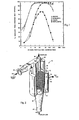
- a first preferred embodiment of the novel apparatus of this invention for achieving flotation in a centrifugal field is shown generally at 10 as an air-sparged hydrocyclone.
- the body of hydrocyclone 10 is configurated generally as a conventional hydrocyclone having an upper, cylindrical section 12 and terminating at its lower end in a downwardly directed cone 18 with an underflow apex 20 for underflow 44.
- a vortex finder 28 is inserted into cylindrical section 12 and provides an outlet for an overflow product 32 through an outlet 30.
- a feed inlet 24 introduces a slurry feed 38 tangentially into cylindrical section 12 to thereby create the cyclonic action therein.
- a section 22 changes the inlet 23 from a circular cross-section to the rectangular cross-section for inlet 24.
- a porous wall 42 is formed as a wall for a portion of hydrocyclone 10. Porous wall 42 is surrounded exteriorly by an air plenum 40 formed by a cylindrical wall 17 extending between an upper flange 15 and a lower flange 16. An air inlet 34 admits air 36 under pressure into air plenum 40.
- air 36 in air plenum 40 is shown schematically as arrows 36a-36c penetrating porous wall 42 and becoming a plurality of discrete air bubbles 48.
- the slurry feed 38 includes a plurality of hydrophobic particles 46 and hydrophilic particles 47 traveling in a counterclockwise cyclonic action as indicated schematically by arrow 39.
- Air bubbles 48 attach themselves under known, conventional flotation techniques and are carried inwardly toward the center vortex of hydrocyclone 10 where they are carried upwardly through the overflow outlet 30 as overflow 32.
- hydrophobic particles 46 are illustrated schematically herein for ease of illustration and presentation.
- both the bubble numbers (N), and the average bubble velocity (u) in a centrifugal field of approximately 80G should be sufficient to provide a surprisingly improved flotation of particles 46 thereby substantially extending the curves of Figure 1 to the left so that recovery of a significantly smaller particle size will be achieved.
- a second preferred embodiment of the novel apparatus of this invention for achieving flotation in a centrifugal field is shown generally at 50 and includes a cylindrical vessel 52 having a coaxial inlet 54 for a feed 55 at an upper end and a coaxial outlet 56 for a product discharge 57 at the lower end.
- a portion of the external wall of vessel 52 is formed as a porous wall 60 which is surrounded by an air plenum 58 formed by a cylindrical wall 59 cooperating between upper and lower flanges 64 and 65, respectively.
- An air inlet 62 provides access for pressurized air 63 into air plenum 58.
- Cyclonic action in vessel 52 is created by a tangentially arrayed wash water inlet 66 for wash water 67 under pressure.
- Wash water 67 entering vessel 52 rotates in a counterclockwise direction as indicated schematically by broken arrow 67a and travels upwardly through the interior of vessel 52 to a second tangential outlet, sink discharge outlet 68 where it becomes sink discharge 69.
- the cyclonic action of wash water 67 as shown by broken arrow 67a creates a corresponding vortex for feed 55 thereby resulting in the more dense particles in feed 55 being carried over by wash water 67 to sink discharge 69.
- Lighter particles continue to feed 55 in an inner vortex, indicated schematically at broken line 55a, are discharged through outlet 56 as product discharge 57.
- the general transition line between the two vortices is shown schematically by broken line 51.
- air 63 passing into air plenum 58 is directed through porous wall 60 thereby forming a plurality of discrete bubbles (schematically similar to bubbles 48, Figure 3) to achieve the novel flotation process in a centrifugal field of this invention.
- Cyclonic flotation separator 80 is configurated as a cylindrical vessel 82 having a coaxial, feed inlet 84 at an upper end for a feed stream 85 and a corresponding, coaxial outlet 86 at a lower end for product discharge 87. Cyclonic action in vessel 82 is created by wash water 95 being tangentially introduced into vessel 82 by a tangential inlet 92. The flow pattern thus created is schematically illustrated at broken lines 95a as a cyclonic vortex.
- the cyclonic vortex in vessel 82 directs wash water 95 upwardly through vessel 82 to discharge outlet 88 as sink discharge 89.
- the corresponding cyclonic action of feed 85 as generated by wash water 95 is shown at vortex 85a (shown in broken lines) with the region between the votices being indicated generally with broken lines as column 81.
- Air indicated schematically at arrow 97, is introduced through an inlet 96 into a mixer 90 where it is intimately blended as a fine dispersion of bubbles (see bubbles 48, Figure 3) in wash water 95.
- Mixer 90 can be of any suitable configuration and may include, for example, an externally-powered mixing apparatus for achieving the fine dispersion of bubbles 48 ( Figure 3) in the process.
- gas bubbles 48 ( Figure 3) may be generated electrolytically or by any other suitable process.
Landscapes
- Life Sciences & Earth Sciences (AREA)
- Engineering & Computer Science (AREA)
- Biotechnology (AREA)
- Cyclones (AREA)
- Physical Water Treatments (AREA)
- Centrifugal Separators (AREA)
- Paper (AREA)
Applications Claiming Priority (2)
| Application Number | Priority Date | Filing Date | Title |
|---|---|---|---|
| US182524 | 1980-08-29 | ||
| US06/182,524 US4399027A (en) | 1979-11-15 | 1980-08-29 | Flotation apparatus and method for achieving flotation in a centrifugal field |
Publications (2)
| Publication Number | Publication Date |
|---|---|
| EP0047135A2 true EP0047135A2 (fr) | 1982-03-10 |
| EP0047135A3 EP0047135A3 (fr) | 1983-02-23 |
Family
ID=22668839
Family Applications (1)
| Application Number | Title | Priority Date | Filing Date |
|---|---|---|---|
| EP81303915A Withdrawn EP0047135A3 (fr) | 1980-08-29 | 1981-08-27 | Appareil et procédé de flottation dans un champ centrifuge |
Country Status (11)
| Country | Link |
|---|---|
| US (2) | US4399027A (fr) |
| EP (1) | EP0047135A3 (fr) |
| JP (1) | JPS5771656A (fr) |
| AU (1) | AU554403B2 (fr) |
| BR (1) | BR8105505A (fr) |
| CA (1) | CA1194622A (fr) |
| MX (1) | MX159100A (fr) |
| NO (1) | NO812923L (fr) |
| PH (1) | PH18766A (fr) |
| PL (1) | PL232844A1 (fr) |
| ZA (1) | ZA815186B (fr) |
Cited By (8)
| Publication number | Priority date | Publication date | Assignee | Title |
|---|---|---|---|---|
| FR2536672A1 (fr) * | 1982-11-26 | 1984-06-01 | Chaudrofrance Sa | Decanteur lamellaire centrifuge |
| GB2158741A (en) * | 1984-05-14 | 1985-11-20 | Hydro Int Ltd | Separation of components of a fluid mixture |
| DE3634323A1 (de) * | 1986-10-08 | 1988-04-21 | Leschonski Kurt Dr Ing | Verfahren und vorrichtung zur fliehkrafttrennung eines flotationssuspensionsgemisches |
| GB2220594A (en) * | 1988-06-27 | 1990-01-17 | Amoco Corp | Controlling output of a cyclone |
| US5456362A (en) * | 1994-05-26 | 1995-10-10 | The University Of British Columbia | Flutation process for the flutation of coarse fractions of potash ores |
| US6119870A (en) * | 1998-09-09 | 2000-09-19 | Aec Oil Sands, L.P. | Cycloseparator for removal of coarse solids from conditioned oil sand slurries |
| GB2362589A (en) * | 2000-05-24 | 2001-11-28 | Kvaerner Process Systems As | Cyclone with intermediate water inlet |
| US7130653B2 (en) | 2002-08-22 | 2006-10-31 | Mediatek Inc. | Power allocation of wireless transmission apparatus |
Families Citing this family (98)
| Publication number | Priority date | Publication date | Assignee | Title |
|---|---|---|---|---|
| US4744890A (en) * | 1979-11-15 | 1988-05-17 | University Of Utah | Flotation apparatus and method |
| US4838434A (en) * | 1979-11-15 | 1989-06-13 | University Of Utah | Air sparged hydrocyclone flotation apparatus and methods for separating particles from a particulate suspension |
| WO1985000760A1 (fr) * | 1983-08-11 | 1985-02-28 | Noel Carroll | Procede et appareil de separation de liquide |
| US4563123A (en) * | 1983-09-12 | 1986-01-07 | Conoco Inc. | Direct coupling of a vortex injector to a centrifugal pump |
| US4511474A (en) * | 1984-01-27 | 1985-04-16 | The United States Of America As Represented By The United States Department Of Energy | Cyclone separator having boundary layer turbulence control |
| DE3610739A1 (de) * | 1986-03-29 | 1987-10-15 | Knauf Res Cottrell | Verfahren und vorrichtung zur messung von parametern in suspensionen |
| US4780201A (en) * | 1987-12-14 | 1988-10-25 | Keeter Kathy L | Apparatus and process to separate and remove extraneous matter from a liquid stream |
| US4855065A (en) * | 1987-12-14 | 1989-08-08 | Keeter Kathy L | Apparatus and process to separate and remove extraneous matter from a liquid stream |
| WO1989007490A1 (fr) * | 1988-02-19 | 1989-08-24 | Conoco Specialty Products Inc. | Separation de liquides |
| AU619814B2 (en) * | 1988-02-19 | 1992-02-06 | Conoco Specialty Products Inc. | Separating liquids |
| US4971685A (en) * | 1989-04-11 | 1990-11-20 | The United States Of America As Represented By The Secretary Of The Interior | Bubble injected hydrocyclone flotation cell |
| JPH0365258A (ja) * | 1989-08-01 | 1991-03-20 | Agency Of Ind Science & Technol | 浮選装置 |
| US4997549A (en) * | 1989-09-19 | 1991-03-05 | Advanced Processing Technologies, Inc. | Air-sparged hydrocyclone separator |
| EP0496765A4 (en) * | 1989-10-19 | 1993-04-07 | The University Of Newcastle Research Associates Limited | Method and apparatus for separation by flotation in a centrifugal field |
| US5224604A (en) * | 1990-04-11 | 1993-07-06 | Hydro Processing & Mining Ltd. | Apparatus and method for separation of wet and dry particles |
| ATE119806T1 (de) * | 1990-06-15 | 1995-04-15 | Heidemij Realisatie Bv | Flotationszyklon. |
| US5114568A (en) * | 1990-07-13 | 1992-05-19 | Earth Solutions, Inc. | Reclamation system for contaminated material |
| US5131980A (en) * | 1990-08-09 | 1992-07-21 | Kamyr, Inc. | Hydrocyclone removal of sticky contaminants during paper recycling |
| US5069751A (en) * | 1990-08-09 | 1991-12-03 | Kamyr, Inc. | Hydrocyclone deinking of paper during recycling |
| US5116488A (en) * | 1990-08-28 | 1992-05-26 | Kamyr, Inc. | Gas sparged centrifugal device |
| US5725764A (en) * | 1990-09-28 | 1998-03-10 | Paul C. Broussard, Sr. | Apparatus for clarifying contaminated fluids |
| US5236590A (en) * | 1991-11-21 | 1993-08-17 | Chevron Research And Technology Company | Process for removing dissolved organics from aqueous compositions |
| US5192423A (en) * | 1992-01-06 | 1993-03-09 | Hydro Processing & Mining Ltd. | Apparatus and method for separation of wet particles |
| US5246116A (en) * | 1992-09-22 | 1993-09-21 | Reynolds Metals Company | Method and apparatus for separation and recovery of the components from foil-containing laminates |
| DE4330635C2 (de) * | 1993-09-10 | 1996-07-11 | Voith Sulzer Stoffaufbereitung | Verfahren zur Abtrennung von Feststoffen durch Flotation und Flotationsvorrichtung |
| US5580446A (en) * | 1994-10-20 | 1996-12-03 | International Paper Company | Screen, vortex apparatus for cleaning recycled pulp and related process |
| US5662811A (en) * | 1995-03-20 | 1997-09-02 | Revtech Industries, Inc. | Method for creating gas-liquid interfacial contact conditions for highly efficient mass transfer |
| US5531904A (en) * | 1995-03-20 | 1996-07-02 | Revtech Industries, Inc. | Gas sparging method for removing volatile contaminants from liquids |
| WO1996029136A1 (fr) * | 1995-03-20 | 1996-09-26 | Grisham Thomas L | Procede et appareil pour optimizer le contact entre un gaz et un liquide |
| US5529701A (en) * | 1995-03-20 | 1996-06-25 | Revtech Industries, Inc. | Method and apparatus for optimizing gas-liquid interfacial contact |
| US6004386A (en) * | 1995-06-21 | 1999-12-21 | Revtech Industries, Inc. | Apparatus for creating gas-liquid interfacial contact conditions for highly efficient mass transfer |
| US5730875A (en) * | 1995-11-17 | 1998-03-24 | Revtech Industries, Inc. | Method and apparatus for optimizing and controlling gas-liquid phase chemical reactions |
| CA2243328C (fr) * | 1996-01-31 | 2001-05-15 | E.I. Du Pont De Nemours And Company | Procede de separation centrifuge de matiere |
| ATE203431T1 (de) * | 1996-04-25 | 2001-08-15 | Fan Separator Gmbh | Vorrichtung zum abscheiden der schwereren von den leichteren anteilen wässriger trüben mittels zentrifugalkraftwirkung |
| US6036871A (en) * | 1996-04-25 | 2000-03-14 | Fan Separator Gmbh | Method and device for separating heavier from lighter parts of aqueous slurries by means of centrifugal force effects |
| US5882530A (en) * | 1997-04-30 | 1999-03-16 | The University Of Akron | Crossflow filter cyclone apparatus |
| US6106711A (en) * | 1997-07-15 | 2000-08-22 | Morse; Dwain E. | Fluid conditioning system and method |
| US6146525A (en) * | 1998-02-09 | 2000-11-14 | Cycteck Environmental, Inc. | Apparatus and methods for separating particulates from a particulate suspension in wastewater processing and cleaning |
| US6183701B1 (en) * | 1998-04-10 | 2001-02-06 | Grt, Inc. | Method of and apparatus for manufacturing methanol |
| US6530484B1 (en) * | 1999-11-18 | 2003-03-11 | Multotec Process Equipment (Proprietary) Ltd. | Dense medium cyclone separator |
| AU770931B2 (en) * | 1999-11-18 | 2004-03-11 | Multotec Process Equipment (Pty) Ltd | Dense medium cyclone separator |
| WO2003012217A1 (fr) * | 2001-07-30 | 2003-02-13 | Vortech-Eco Systems Limited | Separateur centripete |
| US6964740B2 (en) * | 2002-06-25 | 2005-11-15 | Dwain E. Morse | System and method of gas energy management for particle flotation and separation |
| US6830608B1 (en) * | 2002-06-28 | 2004-12-14 | Jaeco Technology, Inc. | Apparatus for contacting large volumes of gas and liquid across microscopic interfaces |
| RU2248849C2 (ru) * | 2002-08-05 | 2005-03-27 | Институт горного дела Севера СО РАН | Способ флотации и центробежная флотационная машина |
| US7736501B2 (en) | 2002-09-19 | 2010-06-15 | Suncor Energy Inc. | System and process for concentrating hydrocarbons in a bitumen feed |
| CA2471048C (fr) * | 2002-09-19 | 2006-04-25 | Suncor Energy Inc. | Cyclone d'hydrocarbures de mousse bitumineuse |
| US7347939B2 (en) * | 2002-10-14 | 2008-03-25 | Clean Water Technology, Inc. | Adjustable contaminated liquid mixing apparatus |
| US20050172808A1 (en) * | 2002-12-09 | 2005-08-11 | Ye Yi | Method and apparatus for removing VOCs from water |
| US6878188B2 (en) * | 2002-12-09 | 2005-04-12 | Ye Yi | Method and apparatus for removing VOCs from water |
| US6849182B2 (en) * | 2003-05-14 | 2005-02-01 | Heron Innovators Inc. | Hydrocyclone having unconstrained vortex breaker |
| CA2455011C (fr) | 2004-01-09 | 2011-04-05 | Suncor Energy Inc. | Traitement de mousse bitumineuse par injection de vapeur en ligne |
| US7429621B2 (en) * | 2004-03-12 | 2008-09-30 | University Of Utah Research Foundation | Cyclone reactor and associated methods |
| US7465391B2 (en) * | 2005-09-09 | 2008-12-16 | Cds Technologies, Inc. | Apparatus for separating solids from flowing liquids |
| EP1767273A1 (fr) * | 2005-09-27 | 2007-03-28 | Genimin | Procédé et appareil pour la concentration de matières à l'état de particules solides |
| US8168071B2 (en) * | 2005-11-09 | 2012-05-01 | Suncor Energy Inc. | Process and apparatus for treating a heavy hydrocarbon feedstock |
| CA2567644C (fr) | 2005-11-09 | 2014-01-14 | Suncor Energy Inc. | Systeme mobile pour l'extraction du sable bitumineux |
| CA2526336C (fr) | 2005-11-09 | 2013-09-17 | Suncor Energy Inc. | Methode et appareil pour extraire du sable bitumineux |
| CA2534704C (fr) | 2006-01-31 | 2020-03-10 | Hydro Processing & Mining Ltd. | Appareil et methode de dissolution d'un gaz dans un liquide |
| US8740195B2 (en) | 2006-01-31 | 2014-06-03 | Jakob H. Schneider | Systems and methods for diffusing gas into a liquid |
| CA2653001C (fr) * | 2006-05-23 | 2011-02-15 | Hideyasu Tsuji | Appareil generateur de fines bulles d'air |
| CA2561539C (fr) * | 2006-09-28 | 2016-11-08 | Hydro Processing & Mining Ltd. | Appareil et methode pour l'accrochage efficace de particules aux bulles de gaz dans une suspension epaisse |
| GB2446580B (en) | 2007-02-16 | 2011-09-14 | Siemens Vai Metals Tech Ltd | Cyclone with classifier inlet and small particle by-pass |
| SG179450A1 (en) * | 2007-04-03 | 2012-04-27 | Siemens Water Tech Corp | Systems and methods for liquid separation |
| CA2682305A1 (fr) * | 2007-04-18 | 2008-10-30 | Thomas A. Valerio | Procede et systemes de tri et de traitement de materiaux recycles |
| JP4980793B2 (ja) * | 2007-05-23 | 2012-07-18 | 新日本製鐵株式会社 | シリコン回収方法及びシリコン回収装置 |
| WO2009067570A1 (fr) * | 2007-11-20 | 2009-05-28 | Paspek Consulting Llc | Traitements à sec permettant de séparer ou de récupérer des métaux non ferreux |
| JP5264256B2 (ja) * | 2008-04-04 | 2013-08-14 | 新日鐵住金株式会社 | 珪酸ナトリウム溶液の製造方法および珪酸ナトリウム溶液の利用方法 |
| KR100882200B1 (ko) * | 2008-06-03 | 2009-02-06 | 주식회사 한국아쿠오시스 | 하이드로사이클론 및 이것을 포함하는 수질오염 방지장치 |
| US8313716B2 (en) * | 2008-07-31 | 2012-11-20 | University Of Utah Research Foundation | Spinning fluids reactor |
| AU2010239235A1 (en) * | 2009-04-23 | 2011-12-08 | Eckman Environmental Corporation | Grey water recycling apparatus and methods |
| CA2689021C (fr) | 2009-12-23 | 2015-03-03 | Thomas Charles Hann | Appareil et procede de regulation de debit par le truchement d'une caisse aspirante |
| CN101972717B (zh) * | 2010-11-05 | 2013-09-18 | 华东理工大学 | 基于进口颗粒调控的旋流器 |
| US9656816B2 (en) * | 2011-08-12 | 2017-05-23 | Cyclone Catalyst Properties Llc | Systems and methods for converter bed unloading and loading |
| GB201116366D0 (en) * | 2011-09-22 | 2011-11-02 | Paxton Richard G | Tubular cyclonic separation & materials processing unit |
| US8506824B1 (en) * | 2012-05-16 | 2013-08-13 | Charles M. Schloss | Method for separating putrescible organic matter from inorganic grit suspended in waste water and sewage |
| US9663385B2 (en) | 2013-11-10 | 2017-05-30 | John D Jones | Liquid purification system |
| US9169725B1 (en) | 2013-11-10 | 2015-10-27 | John D. Jones | Method of stripping crude oil and hydraulic fracturing fluids from water using a gas sparged hydrocyclone |
| US9150435B1 (en) | 2013-11-10 | 2015-10-06 | John D. Jones | Method of stripping volatile organic compounds from water using a gas sparged hydrocyclone |
| US10315202B2 (en) | 2015-07-14 | 2019-06-11 | International Business Machines Corporation | Engulfed nano/micro bubbles for improved recovery of large particles in a flotation cell |
| JP2018529061A (ja) * | 2015-07-15 | 2018-10-04 | ビーエーエスエフ ソシエタス・ヨーロピアBasf Se | エジェクタノズルおよびエジェクタノズルの使用 |
| US10155229B2 (en) | 2015-08-10 | 2018-12-18 | International Business Machines Corporation | Nanobubbles for enhanced interaction between solids and gas volumes |
| US10516169B2 (en) * | 2015-11-12 | 2019-12-24 | Sonata Scientific LLC | Apparatus and method for coating bulk quantities of solid particles |
| US10646885B2 (en) * | 2017-06-28 | 2020-05-12 | Eteros Technologies Inc. | Centrifugal gas separator |
| CA3135562A1 (fr) * | 2020-01-04 | 2021-07-08 | John M. RICHMOND | Appareil de separation de particules |
| JP6792254B1 (ja) * | 2020-02-06 | 2020-11-25 | アキモク鉄工株式会社 | ファインバブル発生器 |
| WO2021195270A1 (fr) * | 2020-03-25 | 2021-09-30 | Crown Iron Works Company | Séparateur hydraulique de graine de coque |
| US11931747B2 (en) * | 2020-05-04 | 2024-03-19 | Finetech Minerals Proprietary Limited | Apparatus, method and process for the recovery of minerals |
| PH12022553506A1 (en) * | 2020-06-18 | 2024-04-29 | Bayer Healthcare Llc | In-line air bubble suspension apparatus for angiography injector fluid paths |
| US11583868B2 (en) | 2020-08-06 | 2023-02-21 | Narmer-engsim LLC | Aerated hydrocyclone apparatus and method for cyclonic froth separation |
| EP4074420A1 (fr) * | 2021-04-15 | 2022-10-19 | Montanuniversität Leoben | Séparation de la matière dans un séparateur à force centrifuge |
| EP4642885A1 (fr) | 2022-12-30 | 2025-11-05 | Neste Oyj | Processus d'extraction liquide-liquide-solide pour récupérer des produits à partir d'un flux d'alimentation contenant de la biomasse |
| AU2023414788A1 (en) | 2022-12-30 | 2025-06-19 | Neste Oyj | Processes and systems for culturing algae |
| WO2024141712A1 (fr) | 2022-12-30 | 2024-07-04 | Neste Oyj | Procédés et systèmes d'élimination de sel d'une mousse contenant une biomasse algale et une solution contenant un sel |
| WO2024141713A1 (fr) | 2022-12-30 | 2024-07-04 | Neste Oyj | Procédés et systèmes d'élimination de sel d'une mousse contenant une biomasse algale et une solution contenant un sel |
| CN116237164A (zh) * | 2023-03-08 | 2023-06-09 | 湖南天童环保有限公司 | 铁矿氧化矿石浮选绿色捕收设备及其生产工艺 |
| WO2025114646A1 (fr) | 2023-11-30 | 2025-06-05 | Neste Oyj | Procédé d'extraction par voie humide amélioré par des conditions acides et chélatantes |
| WO2025114645A1 (fr) | 2023-11-30 | 2025-06-05 | Neste Oyj | Procédé et système de séparation de produits hydrophobes d'algues d'un courant de biomasse algale |
Family Cites Families (27)
| Publication number | Priority date | Publication date | Assignee | Title |
|---|---|---|---|---|
| US2354311A (en) * | 1942-03-18 | 1944-07-25 | Int Comb Ltd | Apparatus for grading powdered material |
| FR1004379A (fr) * | 1947-04-11 | 1952-03-28 | Procédé et appareil de traitement de mélanges fluides hétérogènes, en particulier de pâte à papier | |
| FR1022375A (fr) | 1949-06-18 | 1953-03-04 | Kloeckner Humboldt Deutz Ag | Procédé et installation pour le traitement de minéraux |
| FR998240A (fr) * | 1949-09-02 | 1952-01-16 | Kloeckner Humboldt Deutz Ag | Procédé et dispositif pour la préparation de minéraux |
| FR60294E (fr) * | 1950-05-08 | 1954-10-13 | Jaruza A G Chur | Machine de flottation à gros débit |
| DE1069116B (de) * | 1952-09-24 | 1959-11-19 | Nichols Engineering S. Research Corporation, New- York, N. Y. (V.St.A.) | Verfahren und Vorrichtung zum Abscheiden von feste Stoffe enthaltenden Faserstoffaufschwemmungen an einem Hydrozyklon |
| US2879889A (en) * | 1954-06-03 | 1959-03-31 | Rakowsky Victor | Apparatus for separating mixed products having specific gravities less than one |
| FR1249814A (fr) * | 1957-08-21 | 1961-01-06 | Procédé et dispositif pour la séparation d'un mélange de particules | |
| US3130157A (en) * | 1958-12-15 | 1964-04-21 | Denis F Kelsall | Hydro-cyclones |
| DE1175621B (de) * | 1962-02-14 | 1964-08-13 | Kloeckner Humboldt Deutz Ag | Zentrifugalflotationszelle |
| FR1356704A (fr) * | 1962-10-30 | 1964-03-27 | Appareil pour la séparation de mélanges de macroparticules | |
| US3219186A (en) * | 1962-10-30 | 1965-11-23 | Victor Rakowsky | Whirlpool apparatus |
| DE1182161B (de) | 1963-02-23 | 1964-11-26 | Kloeckner Humboldt Deutz Ag | Zentrifugalflotationszelle |
| US3349548A (en) * | 1964-01-22 | 1967-10-31 | C C Ind | Cyclone separator for separating steam from water |
| US3391787A (en) * | 1966-04-18 | 1968-07-09 | Beloit Corp | Porous cone cleaner |
| US3489680A (en) * | 1967-10-30 | 1970-01-13 | Mobil Oil Corp | Method for breaking a water-in-oil emulsion |
| US3615008A (en) * | 1969-02-17 | 1971-10-26 | Silver Lining Inc | Centrifugal classifying system |
| NL6909273A (fr) * | 1969-06-18 | 1970-12-22 | ||
| US3557956A (en) * | 1970-01-28 | 1971-01-26 | Bergstrom Paper Co | Method for de-inking and removal of certain contaminants from reclaimed paper stock |
| DE2410700A1 (de) | 1974-03-06 | 1975-09-11 | Bayer Ag | Verfahren zur abscheidung von feststoffen aus einem gasstrom und dafuer geeignete vorrichtung |
| SU751437A1 (ru) * | 1975-02-10 | 1980-07-30 | Научно-Исследовательский И Проектно- Конструкторский Институт Обогащения Твердых Горючих Ископаемых "Иотт" | Центробежна флотационна машина |
| SU545385A1 (ru) | 1975-06-04 | 1977-02-05 | Государственный научно-исследовательский институт цветных металлов "Гинцветмет" | Колонна флотационна машина |
| US4208276A (en) * | 1976-07-13 | 1980-06-17 | Bergwerksverband Gmbh | Flotation plant |
| SE410276B (sv) * | 1976-10-20 | 1979-10-08 | Sala International Ab | Dynamisk suspensionsanrikningsseparator |
| SE7612389L (sv) * | 1976-11-05 | 1978-05-06 | Alfa Laval Ab | Forfarande vid centrifugalseparering |
| DE2812105A1 (de) * | 1978-03-20 | 1979-09-27 | Kloeckner Humboldt Deutz Ag | Verfahren und vorrichtung zum trennen von stoffen durch flotation |
| US4279743A (en) * | 1979-11-15 | 1981-07-21 | University Of Utah | Air-sparged hydrocyclone and method |
-
1980
- 1980-08-29 US US06/182,524 patent/US4399027A/en not_active Expired - Lifetime
-
1981
- 1981-07-28 ZA ZA815186A patent/ZA815186B/xx unknown
- 1981-08-12 CA CA000383739A patent/CA1194622A/fr not_active Expired
- 1981-08-14 MX MX188744A patent/MX159100A/es unknown
- 1981-08-25 PH PH26097A patent/PH18766A/en unknown
- 1981-08-27 NO NO812923A patent/NO812923L/no unknown
- 1981-08-27 EP EP81303915A patent/EP0047135A3/fr not_active Withdrawn
- 1981-08-28 JP JP56134365A patent/JPS5771656A/ja active Granted
- 1981-08-28 PL PL23284481A patent/PL232844A1/xx unknown
- 1981-08-28 BR BR8105505A patent/BR8105505A/pt not_active IP Right Cessation
- 1981-08-31 AU AU74778/81A patent/AU554403B2/en not_active Expired
- 1981-11-20 US US06/323,336 patent/US4397741A/en not_active Expired - Lifetime
Cited By (11)
| Publication number | Priority date | Publication date | Assignee | Title |
|---|---|---|---|---|
| FR2536672A1 (fr) * | 1982-11-26 | 1984-06-01 | Chaudrofrance Sa | Decanteur lamellaire centrifuge |
| GB2158741A (en) * | 1984-05-14 | 1985-11-20 | Hydro Int Ltd | Separation of components of a fluid mixture |
| GB2189413A (en) * | 1984-05-14 | 1987-10-28 | Hydro Int Ltd | Separation of components of a fluid mixture |
| US4747962A (en) * | 1984-05-14 | 1988-05-31 | Hydro International Limited | Separation of components of a fluid mixture |
| DE3634323A1 (de) * | 1986-10-08 | 1988-04-21 | Leschonski Kurt Dr Ing | Verfahren und vorrichtung zur fliehkrafttrennung eines flotationssuspensionsgemisches |
| GB2220594A (en) * | 1988-06-27 | 1990-01-17 | Amoco Corp | Controlling output of a cyclone |
| GB2220594B (en) * | 1988-06-27 | 1992-04-22 | Amoco Corp | Method of controlling the separation efficiency of a hydrocyclone |
| US5456362A (en) * | 1994-05-26 | 1995-10-10 | The University Of British Columbia | Flutation process for the flutation of coarse fractions of potash ores |
| US6119870A (en) * | 1998-09-09 | 2000-09-19 | Aec Oil Sands, L.P. | Cycloseparator for removal of coarse solids from conditioned oil sand slurries |
| GB2362589A (en) * | 2000-05-24 | 2001-11-28 | Kvaerner Process Systems As | Cyclone with intermediate water inlet |
| US7130653B2 (en) | 2002-08-22 | 2006-10-31 | Mediatek Inc. | Power allocation of wireless transmission apparatus |
Also Published As
| Publication number | Publication date |
|---|---|
| NO812923L (no) | 1982-03-01 |
| MX159100A (es) | 1989-04-17 |
| US4399027A (en) | 1983-08-16 |
| US4397741A (en) | 1983-08-09 |
| AU7477881A (en) | 1982-03-04 |
| JPS5771656A (en) | 1982-05-04 |
| ZA815186B (en) | 1982-08-25 |
| PH18766A (en) | 1985-09-20 |
| CA1194622A (fr) | 1985-10-01 |
| BR8105505A (pt) | 1982-05-11 |
| JPH0239310B2 (fr) | 1990-09-05 |
| EP0047135A3 (fr) | 1983-02-23 |
| AU554403B2 (en) | 1986-08-21 |
| PL232844A1 (fr) | 1982-03-29 |
Similar Documents
| Publication | Publication Date | Title |
|---|---|---|
| US4399027A (en) | Flotation apparatus and method for achieving flotation in a centrifugal field | |
| US5192423A (en) | Apparatus and method for separation of wet particles | |
| US4744890A (en) | Flotation apparatus and method | |
| US4838434A (en) | Air sparged hydrocyclone flotation apparatus and methods for separating particles from a particulate suspension | |
| US4279743A (en) | Air-sparged hydrocyclone and method | |
| US4971685A (en) | Bubble injected hydrocyclone flotation cell | |
| AHMED et al. | Flotation kinetics | |
| US4997549A (en) | Air-sparged hydrocyclone separator | |
| US11596953B2 (en) | System, method and apparatus for froth flotation | |
| US4981582A (en) | Process and apparatus for separating fine particles by microbubble flotation together with a process and apparatus for generation of microbubbles | |
| US4750994A (en) | Flotation apparatus | |
| US5059309A (en) | Ultrasonic flotation system | |
| US5855769A (en) | Apparatus and method for selective separation of hydrophobic material | |
| US20130153472A1 (en) | Apparatus and method for efficient particle to gas bubble attachment in a slurry | |
| US2967617A (en) | Hydraulic classifier | |
| Rubio et al. | The process of separation of fine mineral particles by flotation with hydrophobic polymeric carrier | |
| US5928125A (en) | Centrifugal flotation cell with rotating drum | |
| US4284499A (en) | Apparatus for the float concentration of ore | |
| Miller et al. | Froth characteristics in air-sparged hydrocyclone flotation | |
| CA1178382A (fr) | Appareil et methode de separation de solides en suspension | |
| Jordan et al. | Rapid flotation using a modified bubble-injected hydrocyclone and a shallow-depth froth separator for improved flotation kinetics | |
| Ntengwe et al. | Optimization of the operating density and particle size distribution of the cyclone overflow to enhance the recovery of the flotation of copper sulphide and oxide minerals | |
| Singh et al. | Gravity concentration of fines and ultrafines | |
| US5340481A (en) | Dense media processing cyclone | |
| WO1993022061A1 (fr) | Cellule de flottation a tourbillons |
Legal Events
| Date | Code | Title | Description |
|---|---|---|---|
| PUAI | Public reference made under article 153(3) epc to a published international application that has entered the european phase |
Free format text: ORIGINAL CODE: 0009012 |
|
| AK | Designated contracting states |
Designated state(s): BE DE FR GB IT NL SE |
|
| PUAL | Search report despatched |
Free format text: ORIGINAL CODE: 0009013 |
|
| AK | Designated contracting states |
Designated state(s): BE DE FR GB IT NL SE |
|
| STAA | Information on the status of an ep patent application or granted ep patent |
Free format text: STATUS: THE APPLICATION IS DEEMED TO BE WITHDRAWN |
|
| 18D | Application deemed to be withdrawn |
Effective date: 19840201 |
|
| RIN1 | Information on inventor provided before grant (corrected) |
Inventor name: MILLER, JAN D. |