EP0047231A2 - Gefässprothese und Verfahren zu deren Herstellung - Google Patents
Gefässprothese und Verfahren zu deren Herstellung Download PDFInfo
- Publication number
- EP0047231A2 EP0047231A2 EP81850140A EP81850140A EP0047231A2 EP 0047231 A2 EP0047231 A2 EP 0047231A2 EP 81850140 A EP81850140 A EP 81850140A EP 81850140 A EP81850140 A EP 81850140A EP 0047231 A2 EP0047231 A2 EP 0047231A2
- Authority
- EP
- European Patent Office
- Prior art keywords
- holes
- vascular prosthesis
- tube
- vascular
- disposed
- Prior art date
- Legal status (The legal status is an assumption and is not a legal conclusion. Google has not performed a legal analysis and makes no representation as to the accuracy of the status listed.)
- Granted
Links
Images




Classifications
-
- B—PERFORMING OPERATIONS; TRANSPORTING
- B29—WORKING OF PLASTICS; WORKING OF SUBSTANCES IN A PLASTIC STATE IN GENERAL
- B29C—SHAPING OR JOINING OF PLASTICS; SHAPING OF MATERIAL IN A PLASTIC STATE, NOT OTHERWISE PROVIDED FOR; AFTER-TREATMENT OF THE SHAPED PRODUCTS, e.g. REPAIRING
- B29C59/00—Surface shaping of articles, e.g. embossing; Apparatus therefor
- B29C59/16—Surface shaping of articles, e.g. embossing; Apparatus therefor by wave energy or particle radiation, e.g. infrared heating
- B29C59/165—Surface shaping of articles, e.g. embossing; Apparatus therefor by wave energy or particle radiation, e.g. infrared heating of profiled articles, e.g. hollow or tubular articles
-
- A—HUMAN NECESSITIES
- A61—MEDICAL OR VETERINARY SCIENCE; HYGIENE
- A61F—FILTERS IMPLANTABLE INTO BLOOD VESSELS; PROSTHESES; DEVICES PROVIDING PATENCY TO, OR PREVENTING COLLAPSING OF, TUBULAR STRUCTURES OF THE BODY, e.g. STENTS; ORTHOPAEDIC, NURSING OR CONTRACEPTIVE DEVICES; FOMENTATION; TREATMENT OR PROTECTION OF EYES OR EARS; BANDAGES, DRESSINGS OR ABSORBENT PADS; FIRST-AID KITS
- A61F2/00—Filters implantable into blood vessels; Prostheses, i.e. artificial substitutes or replacements for parts of the body; Appliances for connecting them with the body; Devices providing patency to, or preventing collapsing of, tubular structures of the body, e.g. stents
- A61F2/0077—Special surfaces of prostheses, e.g. for improving ingrowth
-
- A—HUMAN NECESSITIES
- A61—MEDICAL OR VETERINARY SCIENCE; HYGIENE
- A61F—FILTERS IMPLANTABLE INTO BLOOD VESSELS; PROSTHESES; DEVICES PROVIDING PATENCY TO, OR PREVENTING COLLAPSING OF, TUBULAR STRUCTURES OF THE BODY, e.g. STENTS; ORTHOPAEDIC, NURSING OR CONTRACEPTIVE DEVICES; FOMENTATION; TREATMENT OR PROTECTION OF EYES OR EARS; BANDAGES, DRESSINGS OR ABSORBENT PADS; FIRST-AID KITS
- A61F2/00—Filters implantable into blood vessels; Prostheses, i.e. artificial substitutes or replacements for parts of the body; Appliances for connecting them with the body; Devices providing patency to, or preventing collapsing of, tubular structures of the body, e.g. stents
- A61F2/02—Prostheses implantable into the body
- A61F2/04—Hollow or tubular parts of organs, e.g. bladders, tracheae, bronchi or bile ducts
- A61F2/06—Blood vessels
-
- B—PERFORMING OPERATIONS; TRANSPORTING
- B29—WORKING OF PLASTICS; WORKING OF SUBSTANCES IN A PLASTIC STATE IN GENERAL
- B29C—SHAPING OR JOINING OF PLASTICS; SHAPING OF MATERIAL IN A PLASTIC STATE, NOT OTHERWISE PROVIDED FOR; AFTER-TREATMENT OF THE SHAPED PRODUCTS, e.g. REPAIRING
- B29C35/00—Heating, cooling or curing, e.g. crosslinking or vulcanising; Apparatus therefor
- B29C35/02—Heating or curing, e.g. crosslinking or vulcanizing during moulding, e.g. in a mould
- B29C35/08—Heating or curing, e.g. crosslinking or vulcanizing during moulding, e.g. in a mould by wave energy or particle radiation
- B29C35/0805—Heating or curing, e.g. crosslinking or vulcanizing during moulding, e.g. in a mould by wave energy or particle radiation using electromagnetic radiation
- B29C2035/0838—Heating or curing, e.g. crosslinking or vulcanizing during moulding, e.g. in a mould by wave energy or particle radiation using electromagnetic radiation using laser
-
- B—PERFORMING OPERATIONS; TRANSPORTING
- B29—WORKING OF PLASTICS; WORKING OF SUBSTANCES IN A PLASTIC STATE IN GENERAL
- B29L—INDEXING SCHEME ASSOCIATED WITH SUBCLASS B29C, RELATING TO PARTICULAR ARTICLES
- B29L2031/00—Other particular articles
- B29L2031/753—Medical equipment; Accessories therefor
- B29L2031/7532—Artificial members, protheses
- B29L2031/7534—Cardiovascular protheses
-
- Y—GENERAL TAGGING OF NEW TECHNOLOGICAL DEVELOPMENTS; GENERAL TAGGING OF CROSS-SECTIONAL TECHNOLOGIES SPANNING OVER SEVERAL SECTIONS OF THE IPC; TECHNICAL SUBJECTS COVERED BY FORMER USPC CROSS-REFERENCE ART COLLECTIONS [XRACs] AND DIGESTS
- Y10—TECHNICAL SUBJECTS COVERED BY FORMER USPC
- Y10S—TECHNICAL SUBJECTS COVERED BY FORMER USPC CROSS-REFERENCE ART COLLECTIONS [XRACs] AND DIGESTS
- Y10S623/00—Prosthesis, i.e. artificial body members, parts thereof, or aids and accessories therefor
- Y10S623/901—Method of manufacturing prosthetic device
Definitions
- the invention relates to a vascular prosthesis in the form of a flexible tube which can be implanted in animals or human beings, wherein at least one outer surface layer consists of a soft synthetic material with microdepressions in the external surface of the tube.
- the invention relates to a method in producing a vascular prosthesis of this kind.
- vascular prosthesis It is an indispensible requirement that such a vascular prosthesis should be able to fulfil for a long time,.i.e. for several years, its vitally important function in the organism in which it is implanted.
- the vascular prosthesis is of a material which is not rejected by the organism and which has such mechanical properties that the vascular prosthesis can take up the varying internal pressure to which it may be exposed, that it can bend with a small radius without becoming occluded and that it can be firmly sewn to joining blood vessels, producing a satisfactory anastomosis; without the suture thread cutting through the material.
- the lumen must be bounded by a surface which does not tend to give rise to thrombosis and thromboembolisms, and the external surface of the vascular prosthesis should be compatible with tissue and allow the prosthesis to be anchored by the tissue growing or infiltrationing into the wall of the vessel so that no oedema is formed or inflammation occurs through displacement or twisting of the vascular prosthesis in relation to adjacent tissues. Furthermore, it is necessary for the material in the vascular prosthesis to be able to stand some form of sterilization. Finally, it should be added that the properties listed above must be present at the temperature at which the vascular prosthesis is to be used, namely at body temperature.
- The'vascular prosthesis which has been used for the longest time consists of porous textile material, usually a crimped or resiliently circular-knitted stocking of polymerized ethyleneglycolterephthalate (Dacron). It also occurs in embodiments with a velour covering on the outside or both on the outside and the inside to promote the growing of the surrounding tissue into the implanted vascular prosthesis, even into the boundary surface of the lumen, so that a pseudointimal. coating is obtained on the boundary surface, which is more resistant to blood coagulation than the actual surface of the vascular prosthesis. Deposits of fibrin and cellular material from the blood also contribute to the formation of this coating.
- the vascular prosthesis is covered internally, within a few days, with a biological lining which can be tolerated by the blood and prevents the occurrence of thrombosis or thromboembolisms.
- the textile vascular prostheses must, however, be treated with blood, so-called pre- clotting, before they are implanted, which involves a time-consuming and lengthy pre-treatment.
- the textile vascular.prostheses are accepted by the organism and fulfil their function well if they have a limited length and a sufficiently large internal diameter and work with a rapid flow of blood and under high pressure. If these conditions are not fulfilled, the woven vascular prostheses have a short operative life.
- vascular prostheses have been made of expanded polytetrafluorethylene (Teflon) which forms a network of nodes and flexible fibrils.
- Teflon expanded polytetrafluorethylene
- the advantage of this type of vascular prosthesis is above all that it can be given the desired porosity and the desired flexibility and that no pretreatment with blood is necessary. Moreover, it is easy to suture and is resistant to occlusion.
- a substantial disadvantage, however, is that the vascular-prosthesis has an uneven surface at the inside and cannot be heparinized to prevent particles in the blood from coating the inside of the vascular prosthesis. It is still too early to judge whether this type of vascular prosthesis is better, with regard to its operation, than the vascular prosthesis of textile material.
- German laid open specification 2,149,027 it has been proposed to produce microdepressions in the external surface of an implant by a procedure wherein particles, granulate or fibres of predetermined size and shape are embedded into the material of the external surface of the implant and are then removed again so that depressions remain in the surface, which correspond to the size and shape of the particles, granulate or fibres at the embedding locations.
- the method produces a random distribution of the depressions, and certain parts of the surface may be supplied to a less extent than others.
- the implant may be in the form of a vascular prosthesis but it does not appear to have reached any practical use as such, probably because the microdepressions produced in the manner indicated do not permit a satisfactory growing-in of surrounding tissue to achieve a reliable anchoring of a vascular prosthesis in the organism.
- the invention is a contribution to the efforts made in order to provide a vascular prosthesis which satisfies the requirements discussed above.
- the vascular prosthesis of the kind initially referred to which has been provided according to the invention, has obtained the features which appear from claim 1.
- This vascular prosthesis has a non-permeable wall, which is an important difference from the vascular prostheses now used of a permeable construction. No pre--clotting is therefore required.
- the vascular prosthesis preferably consists of polyurethane with blind holes set obliquely to the radial direction alternately in one direction and the other. Then, in a particularly advantageous manner the holes may be inter-connected in pairs at their inner ends, so that they form a duct from the surface of the vascular prosthesis which extends through the material of the vascular prosthesis and then goes out again to emerge at the surface of the vascular prosthesis.
- the vascular prosthesis can be sutured more easily and reliably when connected to adjacent blood vessels, it is a further advantage to reinforce the wall of the vascular prosthesis with a stocking of textile material embedded in the material.
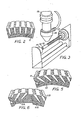
- the vascular prosthesis according to the invention shown therein consists of a moulded, injection-moulded or extruded cylindrical, flexible tube 10 of a synthetic material, for example plastics, preferably polyurethane, which. is compatible with tissue and is available in various degrees of hardness.
- a synthetic material for example plastics, preferably polyurethane, which. is compatible with tissue and is available in various degrees of hardness.
- the material should be soft. Shore numbers of 20 to 25° have proved suitable.
- this material has a negative electrical surface charge, which is an advantage, as mentioned in the introduction, since the material repels thrombocytes as a result thereof.
- materials which do not have such a negative electrical surface charge for example polyvinylacetate, can also be used in the vascular prosthesis according to the invention, if they are suitable for heparinizing, i. e . the incorporation of heparin in the vessel wall at the inside of the tube.
- heparinizing i. e . the incorporation of heparin in the vessel wall at the inside of the tube.
- the inside becomes repellant to thrombocytes and particles in the blood are prevented from coating the inside of the vascular prosthesis, and so the occurrence oi thromboses and thromboembolisms is prevented.
- Even materials which already have a negative surface charge can be heparinized at the inside of the tube if it is desired to increase the thrombocyte-repelling effect.
- Polyethylene, polytetrafluorethylene and silicone rubber may be mentioned as further examples of materials which are suitable for the vascular prosthesis according to the invention.
- polyvinyl chloride for example is unsuitable, since it changes during the laser treatment. The changes are manifested by discolouring of the material. Materials which undergo structural changes during laser treatment, which are manifested as carbonization of the surface or discolouration of the material, should not be used for.the vascular prosthesis according to the invention.
- the material which is used for the vascular prosthesis it is required of the material which is used for the vascular prosthesis, that it should be accepted by the organism and should not be rejected by the organism after the implantation, and that it should have a negative electrical surface charge or be able to be heparinized. Furthermore, the material shoul-d be able to be treated with a laser without undergoing structural changes, and it should have such mechanical properties that it can withstand the stresses to which it is exposed not only during manufacture but also when the vascular.prosthesis is implanted in the organism. The material should be soft so that the vascular prosthesis can bend with a small radius without a tendency to so-called cracking.
- the material is soft is also a prerequisite for the vascular prosthesis to seal against joining blood vessels, which have often grown stiff due to calcification, during the connection to these blood vessels. At the same time, however, the material should afford adequate securing means for the suture thread which should not tend to cut through the material. As will be shown later, in connection with another embodiment of the invention, the anchoring of the suture thread can, however, be improved by inserting a reinforcement in the tube wall. Finally, it is, of course, necessary for the material of the vascular prosthesis to be able to stand some form of sterilization, for example beta or gamma sterilization. It may be added that the properties listed must be present at the temperature at which the vascular prosthesis is to be used, namely at body temperature.
- the vascular prosthesis In order that the vascular prosthesis may be able to fulfil its purpose, it must be able to be anchored in the body by the growing-in and infiltration of the tis.sue into the wall of the prosthesis to eliminate oedema and inflammation. In order that this growing-in may be uniform over the whole external surface of the vascular prosthesis, this is formed with a regular pattern of microdepressions in the form of blind holes 11. It is an essential requirement that the whole surface should be uniformly provided with these holes.
- the holes are disposed substantially radially in the embodiment shown in Figures 1 and 2.
- the holes are produced by laser treatment which can be effected in the manner shown in Figure 3.
- the tube 10 is passed onto a mandrel 12 which is secured between a chuck 13 and a tailstock 14.
- the chuck and the tailstock may constitute parts of a conventional lathe.
- a laser partially indicated at 15, is placed with its focussing lens system 16 above the tube 10. The laser beam is directed radially towards the tube. While the tube is rotated and displaced axially, the laser is pulsated to produce a hole in the tube wall on each pulse, the holes thus formed coming to lie on a continuous helical line round the outside of the tube.
- the tube was rotated with a pitch of 0.30 mm.
- the pulse frequency of the laser and the rate of rotation of the tube were selected so that the spacing between the holes along the helical line was about 0.30 mm.
- the laser used was a 500 W C0 2 laser with radiation in the form of a parallel beam of infrared light with a wavelength of 10.6 ⁇ m.
- the diameter of the beam was about 12 mm, and this beam was focussed by the lens 16 on the surface of the stock material.
- the pulse period In order that well-defined holes may be obtained, though the tube is rotating at a constant speed, the pulse period must be selected short in comparison with the interval between two pulses; with a pulse rate of 100 - 400 pulses per second, the pulse period is of the order of 10 - 100 ⁇ s.
- the hole diameter With correct focussing of the laser beam on the tube, the hole diameter is 0.10 mm, but the hole diameter, can be increased by defocussing slightly.
- the depth of hole is determined by the energy of the laser pulse, and this depth should appropriately be selected so that the distance from the bottom of the hole to the inner wall corresponds to approximately 1/3 of the thickness of the.tube wall.
- the hole diameter was 0.150 mm and the hole depth 0.30 mm with a wall thickness of 0.40 mm.
- the hole spacing was 0.30 mm and the pitch of the helical line 0.30 mm. There were about 11 holes on each square millimetre of the surface of the vascular prosthesis.
- the hole diameter was 0.125 mm and the hole depth again 0.30 mm with a wall thickness of 0.40 mm.
- the hole spacing was 0.25 mm and the pitch likewise 0.25 mm. This corresponds to 16 holes/mm 2 .
- the hole pattern which is obtained by the laser treatment is very regular and reproducible, since the pulse energy and pulse rate of the laser can be adjusted accurately.
- the number of holes per unit of surface can be altered by altering the pitch and the spacing between the holes along the helical line.
- the individual holes will be very regular.
- the method of producing microdepressions in this manner is clean and contact-free, since the material which is removed by means of the laser is gasified instantaneously and blown away.
- the treatment is carried out in an inert atmosphere .by a stream of argon being blown towards the tube during the treatment.
- Figure 4 shows a vascular prosthesis with holes 11 arranged in the same manner as in Figures 1 and 2.
- a circular-knitted stocking 17'of textile material preferably of Dacron, so that the tube has a portion 10A at the outside of the stocking, in which the holes 11 are provided, and an internal portion 10B at the inside of the stocking, which forms the interior of the vascular prosthesis.
- the stocking 17' serves to bring about the anchoring of the suture during the connection of the vascular prosthesis, so that it is not necessary to rely only on the material of the tube for the anchoring of the suture, and eliminates the risk of the suture cutting through this material.
- the stocking 17' can be laid in the material in the tube during the moulding, injectionmoulding or extrusion thereof.
- the tube can be produced of a composite material, meaning that the portion 10A is of a material different from that of the portion 10B.
- a material can be selected for the portion 10A which is suitable for laser treatment and for growing-in and infiltration of surrounding tissue, while a material can be selected for the portion 10B which is suitable to form the lumen of the vascular prosthesis, i.e. a material without a tendency to form thromboses or thromboembolisms.
- the holes 11 are disposed radially, i.e. they are at right angles to the external surface of the vascular prosthesis and to its longitudinal axis.
- the laser may, however, be directed obliquely to the external surface of the vascular prosthesis but still in a plane which is at right angles to the longitudinal axis of the tube 10 and in such a case the holes 11 are set obliquely as shown in Figure 5.
- a suitable inclination to the radial direction is of the order of 45°. As a result of the inclination of the holes, these can be made longer at unaltered wall thickness and an unaltered spacing between the inner ends of the holes and the boundary surface of the lumen.
- the inclination and the increased length of the blind holes afford a better anchoring of the vascular prosthesis during the growing-in of surrounding tissue into the implanted vascular prosthesis.
- FIG.6 illustrates a further development of the embodiment as shown in Figures 5, according to which the blind holes are inclined alternately to one side and the other but still extend in planes which are at right angles to the longitudinal axis of the tube.
- Holes 11A are situated on a helical line with a pitch of 0.60 mm substantially at 45° to the radial direction, i.e. substantially at 45° to the external surface of the tube, while holes 118 are disposed on another helical line with a pitch of 0.60 mm but offset axially by 0.30 mm in relation to the first helical line. These holes also form an angle of substantially 45° to the radial direction of the tube but are inclined in the opposite direction to the holes 11A.
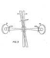
- the beam of light from the laser 15 is directed towards a semi-transparent mirror 17 at an angle of 45°, and the divided beam is transmitted further on the one hand via two mirrors 18 and 19 to a lens 16A and on the other hand via a mirror 20 to a lens 16B.
- the lenses 16A and 16B are situated at opposite sides of the tube 10 set up in the lathe to direct their beams towards the tube from opposite . directions. This is also illustrated in Figures 9 and 10, and as can best be seen from Figure 10, the beams impinge.on the tube below the axis at the points 21A and 21B, which are offset by 45° from the horizontal plane, to produce the holes 11A and 11B, respectively.
- the surface layer of the vascular prosthesis acquires the character of a porous material with communicating cells. It is desirable that the surface layer should be as porous as possible without jeopardizing the strength.
- the holes disposed on one and the same helical line are connected to one another, a hole 11A substantially at an angle of 45° to the external surface of the tube communicating at its inner end with another hole 11B which is situated on the same helical line as the hole 11A and is directed substantially at an angle of 45° to the external surface of the tube but is inclined in the opposite direction to the hole 11A.
- the holes 11A and 11B meet at their inner ends substantially at a right angle.
- the hole 11A has its mouth at the external surface of the tube in common with another hole 11B', inclined in the opposite direction to the hole 11A, and the hole 11B has. its mouth on the external surface of the tube in common with another hole 11A' inclined in the opposite direction to the hole 11B.
- the tube wall has a reinforcing stocking 17:
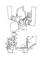
- the apparatus shown in Figures 15 and 16 is set up for the production of the embodiment as shown in Figure 14 but can also be used for the production of other described embodiments of the vascular prosthesis according to the invention. It comprises an elongated stand 22 with parallel guide bars 23 on which a carriage 24 is guided for displacement. Mounted on this carriage is an electric motor 25 with a change speed gear 26 to the output shaft of which there is coupled a shaft 27 which extends parallel to the guide bars 23 and can be rotated,by means of the motor at an accurately adjusted rate of rotation.
- the output shaft of the change speed gear is also coupled to a shaft 28 which is parallel to the shaft 27 and is mounted in a headstock 29 mounted carriage, by means of a play-free transmission 30 with the ratio 1:1; this transmission may consist, for example, of a so-called Daimler-Benz gear.
- a chuck 31 mounted on the shaft 28 is a chuck 31 for securing the tube 10 which is to form the vascular prosthesis and which is passed onto a mandrel.
- a linear feeder 32 Fixedly mounted in. the stand 22 is a linear feeder 32, the bar 27 being engaged therewith.
- this linear feeder causes an axial displacement of the bar accurately adjusted to the speed of rotation, and the linear feeder which is adjustable with re- qard to the relationship between speed of rotation and displacement.
- the shaft On axial displacement of the shaft to the left with regard to Figure 15, during the rotation of the shaft, the shaft is taken up, in a protective tube 33 which is disposed in the stand in parallel to the guide bars 23.
- the tube 10 extends through a guide bushing 34 which is disposed on a carriage 35 which can travel freely on the guide bars 23.
- This carriage is initially placed substantially in the middle between the change speed gear 26 and the linear feeder 32.
- the shaft 27 passes freely through the carriage.
- Two fixed guide bushings 35 are also disposed on the stand.
- the carriage 24 is pulled towards the left displacing the tube 10 axially through the guide bushings 34 and 35 into a guide tube 36 which is fixedly mounted in the stand in parallel to the guide bars 23, the tube 10 being rotated at the same time and at the same speed as the shaft 27 via the transmission 30.
- a la-ser of the kind indicated, earlier, partially indicated at 15, is stationarily mounted associated with the stand 22.
- the bundle of rays from the laser is directed towards a semi-transparent mirror 17 at an angle of 45 0 , and the divided beam is transmitted further on the one hand via a mirror 18 to a lens 16A and on the other hand via a mirror 20 to a lens 16B.
- the lenses are adapted to direct their beams towards the tube 10 set up in the apparatus at an angle of 90° to one another; see Figure 17.
- the mirror 17 is disposed in a unit 37 which is mounted on the laser 15, while the mirror 18 and the lens 16A are disposed in a unit 38 which is connected to the unit 37 by means of a rotary coupling 39, and the mirror 20 and the lens 16B are disposed in a unit 40 which is connected to the unit 37 by means of a rotary coupling 41 so that it is possible to direct the laser beams in various directions towards the tube 10.
- the laser beams are directed radially towards the tub.e to produce holes on a helical line when the laser is pulsated with simultaneous rotation and axial displacement of the tube 10 on rotation of the motor 25.
- the guide bushing 34 provides a support for the tube so that it does not hang down or shake during the treatment.
- the carriage 25 gradually entrains the carriage 35 in its movement.
- the outer surface of the vascular prosthesis can be covered with holes in a much more dense pattern than that illustrated in the drawings, and even so densely that the entrances of adjacent holes partly overlaps each other. Further, it is possible to cover the surface with holes having rather a conical shape, that is that the diameter of the holes is gradually decreasing inwards. Such holes are easily obtained by suitable focusation of the lense system of the laser.
- possible coatings on the inside of the prosthesis one may, as a supplement or alternative to possible heparinization, provide the prosthesis with a thin hydrophilic coating containing e.g.
- polyvinylpyrrolidone or other innocuous hydrophilic polymers known to prevent the formation of blood-clots and giving a slippery surface with low frictional resistance against 'water-based liquids such as blood.
- Methods, for obtaining such hydrophilic coatings are known in connection with production of catheters; see e.g. German laid open specification 2,828,617.
Landscapes
- Health & Medical Sciences (AREA)
- Cardiology (AREA)
- Oral & Maxillofacial Surgery (AREA)
- Transplantation (AREA)
- Engineering & Computer Science (AREA)
- Biomedical Technology (AREA)
- Heart & Thoracic Surgery (AREA)
- Vascular Medicine (AREA)
- Life Sciences & Earth Sciences (AREA)
- Animal Behavior & Ethology (AREA)
- General Health & Medical Sciences (AREA)
- Public Health (AREA)
- Veterinary Medicine (AREA)
- Toxicology (AREA)
- Gastroenterology & Hepatology (AREA)
- Pulmonology (AREA)
- Prostheses (AREA)
- Materials For Medical Uses (AREA)
- Macromonomer-Based Addition Polymer (AREA)
- Steroid Compounds (AREA)
- Medicines Containing Antibodies Or Antigens For Use As Internal Diagnostic Agents (AREA)
Priority Applications (1)
| Application Number | Priority Date | Filing Date | Title |
|---|---|---|---|
| AT81850140T ATE7357T1 (de) | 1980-08-28 | 1981-08-24 | Gefaessprothese und verfahren zu deren herstellung. |
Applications Claiming Priority (2)
| Application Number | Priority Date | Filing Date | Title |
|---|---|---|---|
| SE8006024A SE444640B (sv) | 1980-08-28 | 1980-08-28 | I djur eller menniska implanterbar kerlprotes samt sett for dess framstellning |
| SE8006024 | 1980-08-28 |
Publications (3)
| Publication Number | Publication Date |
|---|---|
| EP0047231A2 true EP0047231A2 (de) | 1982-03-10 |
| EP0047231A3 EP0047231A3 (en) | 1982-03-31 |
| EP0047231B1 EP0047231B1 (de) | 1984-05-09 |
Family
ID=20341617
Family Applications (1)
| Application Number | Title | Priority Date | Filing Date |
|---|---|---|---|
| EP81850140A Expired EP0047231B1 (de) | 1980-08-28 | 1981-08-24 | Gefässprothese und Verfahren zu deren Herstellung |
Country Status (13)
| Country | Link |
|---|---|
| US (1) | US4729766A (de) |
| EP (1) | EP0047231B1 (de) |
| JP (1) | JPS5772638A (de) |
| AT (1) | ATE7357T1 (de) |
| AU (1) | AU552482B2 (de) |
| CA (1) | CA1170404A (de) |
| DE (1) | DE3163505D1 (de) |
| DK (1) | DK377981A (de) |
| ES (1) | ES260102Y (de) |
| FI (1) | FI812659L (de) |
| IE (1) | IE52733B1 (de) |
| NO (1) | NO153793C (de) |
| SE (1) | SE444640B (de) |
Cited By (10)
| Publication number | Priority date | Publication date | Assignee | Title |
|---|---|---|---|---|
| EP0162604A1 (de) * | 1984-04-25 | 1985-11-27 | Minnesota Mining And Manufacturing Company | Implantat mit Verankerungsfläche |
| US4673409A (en) * | 1984-04-25 | 1987-06-16 | Minnesota Mining And Manufacturing Company | Implant with attachment surface |
| WO1994013224A1 (en) * | 1992-12-11 | 1994-06-23 | W.L. Gore & Associates, Inc. | A prosthetic vascular graft |
| US5413597A (en) * | 1990-12-29 | 1995-05-09 | Krajicek; Milan | Three-layer vascular prostheses |
| WO1997042910A1 (en) * | 1996-05-14 | 1997-11-20 | Cardia Catheter Co. | Tubular stent for use in medical applications |
| US5716395A (en) * | 1992-12-11 | 1998-02-10 | W.L. Gore & Associates, Inc. | Prosthetic vascular graft |
| US5931865A (en) * | 1997-11-24 | 1999-08-03 | Gore Enterprise Holdings, Inc. | Multiple-layered leak resistant tube |
| US6027863A (en) * | 1991-09-05 | 2000-02-22 | Intratherapeutics, Inc. | Method for manufacturing a tubular medical device |
| US6107004A (en) * | 1991-09-05 | 2000-08-22 | Intra Therapeutics, Inc. | Method for making a tubular stent for use in medical applications |
| US8211184B2 (en) | 2009-04-20 | 2012-07-03 | Michael D. Ries | Acetabular cup |
Families Citing this family (58)
| Publication number | Priority date | Publication date | Assignee | Title |
|---|---|---|---|---|
| US4882283A (en) * | 1987-11-17 | 1989-11-21 | Phillips Petroleum Company | Heat exchange apparatus |
| US4927410A (en) * | 1988-11-18 | 1990-05-22 | University Of South Florida | Method for fabricating prosthesis material |
| EP0417034B1 (de) * | 1989-09-06 | 1994-06-01 | SULZER Medizinaltechnik AG | Implantat mit Verankerungsflächen für Knochengewebe |
| US4965430A (en) * | 1989-09-18 | 1990-10-23 | Dow Corning Wright Corp. | Method of laser machining molds with microtextured surfaces |
| US5246530A (en) * | 1990-04-20 | 1993-09-21 | Dynamet Incorporated | Method of producing porous metal surface |
| WO1991016012A1 (en) * | 1990-04-20 | 1991-10-31 | Dynamet, Inc. | Porous metal surface and method of production |
| IT1248934B (it) * | 1990-06-01 | 1995-02-11 | Fidia Spa | Membrane forate biocompatibili,processi per la loro preparazione,loro impiego come supporto per la crescita in vitro di cellule epiteliali, pelli artificiali cosi' ottenute e loro impiego nei trapianti di pelle |
| US5139480A (en) * | 1990-08-22 | 1992-08-18 | Biotech Laboratories, Inc. | Necking stents |
| EP0475358B1 (de) * | 1990-09-13 | 1994-12-14 | THERA Patent GmbH & Co. KG Gesellschaft für industrielle Schutzrechte | Implantierbare prothese |
| US5108413A (en) * | 1990-12-20 | 1992-04-28 | Moyers Robert E | Dilator for opening the lumen of a tubular organ |
| US5405377A (en) * | 1992-02-21 | 1995-04-11 | Endotech Ltd. | Intraluminal stent |
| US5683448A (en) * | 1992-02-21 | 1997-11-04 | Boston Scientific Technology, Inc. | Intraluminal stent and graft |
| US5782904A (en) | 1993-09-30 | 1998-07-21 | Endogad Research Pty Limited | Intraluminal graft |
| US6689158B1 (en) | 1993-09-30 | 2004-02-10 | Endogad Research Pty Limited | Intraluminal graft |
| US5609624A (en) * | 1993-10-08 | 1997-03-11 | Impra, Inc. | Reinforced vascular graft and method of making same |
| US6165213A (en) * | 1994-02-09 | 2000-12-26 | Boston Scientific Technology, Inc. | System and method for assembling an endoluminal prosthesis |
| US5609627A (en) * | 1994-02-09 | 1997-03-11 | Boston Scientific Technology, Inc. | Method for delivering a bifurcated endoluminal prosthesis |
| US6051020A (en) | 1994-02-09 | 2000-04-18 | Boston Scientific Technology, Inc. | Bifurcated endoluminal prosthesis |
| US6582461B1 (en) | 1994-05-19 | 2003-06-24 | Scimed Life Systems, Inc. | Tissue supporting devices |
| DE69518435T3 (de) | 1994-06-08 | 2004-07-22 | CardioVascular Concepts, Inc., Portola Valley | System zur Herstellung eines abzweigenden Transplantats |
| CA2163824C (en) * | 1994-11-28 | 2000-06-20 | Richard J. Saunders | Method and apparatus for direct laser cutting of metal stents |
| US5711969A (en) * | 1995-04-07 | 1998-01-27 | Purdue Research Foundation | Large area submucosal tissue graft constructs |
| US6010530A (en) * | 1995-06-07 | 2000-01-04 | Boston Scientific Technology, Inc. | Self-expanding endoluminal prosthesis |
| FR2737664B1 (fr) * | 1995-08-08 | 1998-12-24 | Vascor Inc | Procede pour la production d'un dispositif implantable hemocompatible, et dispositif implantable ainsi produit |
| US6045557A (en) * | 1995-11-10 | 2000-04-04 | Baxter International Inc. | Delivery catheter and method for positioning an intraluminal graft |
| US5658475A (en) * | 1996-03-11 | 1997-08-19 | International Business Machines Corporation | Apparatus for laser texturing disks |
| US5755791A (en) * | 1996-04-05 | 1998-05-26 | Purdue Research Foundation | Perforated submucosal tissue graft constructs |
| US5948288A (en) * | 1996-05-28 | 1999-09-07 | Komag, Incorporated | Laser disk texturing apparatus |
| US5968068A (en) * | 1996-09-12 | 1999-10-19 | Baxter International Inc. | Endovascular delivery system |
| IT1289815B1 (it) * | 1996-12-30 | 1998-10-16 | Sorin Biomedica Cardio Spa | Stent per angioplastica e relativo procedimento di produzione |
| US5893989A (en) * | 1997-02-19 | 1999-04-13 | Lasag Ag | Laser machining device, in particular for machining track rods |
| US20080086214A1 (en) * | 1998-08-31 | 2008-04-10 | Wilson-Cook Medical Inc. | Medical device having a sleeve valve with bioactive agent |
| US20070016306A1 (en) * | 1998-08-31 | 2007-01-18 | Wilson-Cook Medical Inc. | Prosthesis having a sleeve valve |
| US6746489B2 (en) * | 1998-08-31 | 2004-06-08 | Wilson-Cook Medical Incorporated | Prosthesis having a sleeve valve |
| US7118600B2 (en) | 1998-08-31 | 2006-10-10 | Wilson-Cook Medical, Inc. | Prosthesis having a sleeve valve |
| US6517571B1 (en) | 1999-01-22 | 2003-02-11 | Gore Enterprise Holdings, Inc. | Vascular graft with improved flow surfaces |
| US6278079B1 (en) | 1999-02-09 | 2001-08-21 | Edwards Lifesciences Corp. | Laser cutting of fabric grafts |
| US6780497B1 (en) * | 1999-08-05 | 2004-08-24 | Gore Enterprise Holdings, Inc. | Surface modified expanded polytetrafluoroethylene devices and methods of producing the same |
| US6344056B1 (en) | 1999-12-29 | 2002-02-05 | Edwards Lifesciences Corp. | Vascular grafts for bridging a vessel side branch |
| US6663667B2 (en) | 1999-12-29 | 2003-12-16 | Edwards Lifesciences Corporation | Towel graft means for enhancing tissue ingrowth in vascular grafts |
| US20040088037A1 (en) * | 2000-12-27 | 2004-05-06 | American Medical Systems, Inc. | Method and apparatus for making a braided stent with spherically ended wires |
| DE10159708A1 (de) * | 2001-12-05 | 2003-06-18 | Bayer Ag | Alkalichlorid-Elektrolysezelle mit Gasdiffusionselektroden |
| EP1590018B1 (de) * | 2003-01-28 | 2012-09-26 | Gambro Lundia AB | Vorrichtung zur überwachung eines vaskulärenzugangs zu einem patienten |
| US20060106451A1 (en) * | 2004-11-18 | 2006-05-18 | Yuri Busiashvili | Electronic anti-coagulation stent for intra-arterial deployment |
| JP2006150385A (ja) * | 2004-11-26 | 2006-06-15 | Canon Inc | レーザ割断方法 |
| US8007992B2 (en) | 2006-10-27 | 2011-08-30 | Edwards Lifesciences Corporation | Method of treating glutaraldehyde-fixed pericardial tissue with a non-aqueous mixture of glycerol and a C1-C3 alcohol |
| US8221505B2 (en) * | 2007-02-22 | 2012-07-17 | Cook Medical Technologies Llc | Prosthesis having a sleeve valve |
| US8646444B2 (en) * | 2007-03-27 | 2014-02-11 | Electrolux Home Products, Inc. | Glide rack |
| EP2393627B1 (de) | 2009-02-03 | 2018-05-09 | Abbott Cardiovascular Systems Inc. | Mehrfachstrahllasersystem zur herstellung von stents |
| EP2393625A1 (de) * | 2009-02-03 | 2011-12-14 | Abbott Cardiovascular Systems Inc. | Verbesserter laserschneidprozess zur herstellung von stents |
| EP2393628B1 (de) * | 2009-02-03 | 2017-06-21 | Abbott Cardiovascular Systems Inc. | Verbessertes laserschneidsystem |
| EP2336586B1 (de) * | 2009-12-15 | 2013-08-14 | Maxon Motor AG | Verfahren zum Erzeugen eines Presssitzes eines Bauteils auf einer Welle |
| BR122014006876B1 (pt) | 2010-03-23 | 2020-09-29 | Edwards Lifesciences Corporation | Método para preparar material de membrana de tecido bioprotético |
| US8556511B2 (en) | 2010-09-08 | 2013-10-15 | Abbott Cardiovascular Systems, Inc. | Fluid bearing to support stent tubing during laser cutting |
| US10238771B2 (en) | 2012-11-08 | 2019-03-26 | Edwards Lifesciences Corporation | Methods for treating bioprosthetic tissue using a nucleophile/electrophile in a catalytic system |
| JPWO2016076416A1 (ja) * | 2014-11-13 | 2017-10-05 | 国立研究開発法人国立循環器病研究センター | 結合組織体形成基材及び基材取出具 |
| IT201900003299A1 (it) * | 2019-03-07 | 2020-09-07 | Telea Biotech S R L | Metodo di preparazione alla rivitalizzazione di un tessuto acellulare |
| TWI813320B (zh) * | 2022-06-06 | 2023-08-21 | 昱捷股份有限公司 | 植體 |
Family Cites Families (22)
| Publication number | Priority date | Publication date | Assignee | Title |
|---|---|---|---|---|
| US3105492A (en) * | 1958-10-01 | 1963-10-01 | Us Catheter & Instr Corp | Synthetic blood vessel grafts |
| US3700380A (en) * | 1970-10-01 | 1972-10-24 | Tecna Corp | Surface or lining compatible with blood or other tissue |
| CA961116A (en) * | 1970-10-19 | 1975-01-14 | Heinrich Schmidt | Method and apparatus for perforating foils and thin metal sheets, especially for fine, slot-shaped openings |
| GB1371624A (en) * | 1971-03-26 | 1974-10-23 | Atomic Energy Authority Uk | Optical processing of materials |
| CH547631A (de) * | 1972-02-02 | 1974-04-11 | Sulzer Ag | Schaft fuer knochenimplantate. |
| CH565020A5 (de) * | 1973-04-03 | 1975-08-15 | Filtrox Maschinenbau Ag | |
| US4070514A (en) * | 1973-06-05 | 1978-01-24 | The United States Of America As Represented By The United States Department Of Energy | Method of fabricating graphite for use as a skeletal prosthesis and product thereof |
| US3914802A (en) * | 1974-05-23 | 1975-10-28 | Ebert Michael | Non-thrombogenic prosthetic material |
| US4073999A (en) * | 1975-05-09 | 1978-02-14 | Minnesota Mining And Manufacturing Company | Porous ceramic or metallic coatings and articles |
| GB1552388A (en) * | 1976-05-14 | 1979-09-12 | Macgregor D C | Cardiovascular prostheses |
| JPS5328996A (en) * | 1976-08-31 | 1978-03-17 | Asahi Chemical Ind | Antithrombotic tubular member |
| JPS5469896A (en) * | 1977-11-15 | 1979-06-05 | Koyo Seiko Co Ltd | Method of machining work outer surface with laser beam |
| DE2804991A1 (de) * | 1978-02-06 | 1979-08-16 | Hauni Werke Koerber & Co Kg | Filterzigarette mit einem aus mindestens zwei filterkomponenten bestehenden mundstueck, verfahren zur herstellung einer filterzigarette und vorrichtung zum ausueben des verfahrens |
| DE2811591C2 (de) * | 1978-03-17 | 1986-08-14 | Sigri GmbH, 8901 Meitingen | Gallengangendoprothese |
| US4280500A (en) * | 1978-03-31 | 1981-07-28 | Kazuaki Ono | Tubular flexible medical instrument |
| JPS6045247B2 (ja) * | 1978-07-07 | 1985-10-08 | 住友金属工業株式会社 | 高エネルギ−ビ−ムによる鋼製品表面の熱処理方法 |
| US4200382A (en) * | 1978-08-30 | 1980-04-29 | Polaroid Corporation | Photographic processing roller and a novel method which utilizes a pulsed laser for manufacturing the roller |
| JPS5548949A (en) * | 1978-10-02 | 1980-04-08 | Jones Geraint A C | Scribing device and method |
| JPS6037733B2 (ja) * | 1978-10-12 | 1985-08-28 | 住友電気工業株式会社 | 管状臓器補綴材及びその製造方法 |
| JPS6037735B2 (ja) * | 1978-10-18 | 1985-08-28 | 住友電気工業株式会社 | 人工血管 |
| LU80792A1 (fr) * | 1979-01-15 | 1980-08-08 | Ntre De Rech Metallurg Ct Voor | Dispsitif et procede pour effectuer des perforations a la surface des cylindres de laminoirs |
| US4377736A (en) * | 1981-08-14 | 1983-03-22 | General Electric Company | Method and apparatus for removing material from a surface |
-
1980
- 1980-08-28 SE SE8006024A patent/SE444640B/sv not_active IP Right Cessation
-
1981
- 1981-08-10 AU AU73939/81A patent/AU552482B2/en not_active Ceased
- 1981-08-19 NO NO812800A patent/NO153793C/no unknown
- 1981-08-24 AT AT81850140T patent/ATE7357T1/de not_active IP Right Cessation
- 1981-08-24 IE IE1936/81A patent/IE52733B1/en unknown
- 1981-08-24 DE DE8181850140T patent/DE3163505D1/de not_active Expired
- 1981-08-24 EP EP81850140A patent/EP0047231B1/de not_active Expired
- 1981-08-26 JP JP56132663A patent/JPS5772638A/ja active Pending
- 1981-08-26 DK DK377981A patent/DK377981A/da not_active Application Discontinuation
- 1981-08-27 ES ES1981260102U patent/ES260102Y/es not_active Expired
- 1981-08-27 FI FI812659A patent/FI812659L/fi not_active Application Discontinuation
- 1981-08-27 CA CA000384711A patent/CA1170404A/en not_active Expired
-
1985
- 1985-04-22 US US06/725,153 patent/US4729766A/en not_active Expired - Fee Related
Cited By (15)
| Publication number | Priority date | Publication date | Assignee | Title |
|---|---|---|---|---|
| EP0162604A1 (de) * | 1984-04-25 | 1985-11-27 | Minnesota Mining And Manufacturing Company | Implantat mit Verankerungsfläche |
| US4608052A (en) * | 1984-04-25 | 1986-08-26 | Minnesota Mining And Manufacturing Company | Implant with attachment surface |
| US4673409A (en) * | 1984-04-25 | 1987-06-16 | Minnesota Mining And Manufacturing Company | Implant with attachment surface |
| US5413597A (en) * | 1990-12-29 | 1995-05-09 | Krajicek; Milan | Three-layer vascular prostheses |
| US6107004A (en) * | 1991-09-05 | 2000-08-22 | Intra Therapeutics, Inc. | Method for making a tubular stent for use in medical applications |
| US6027863A (en) * | 1991-09-05 | 2000-02-22 | Intratherapeutics, Inc. | Method for manufacturing a tubular medical device |
| GB2289625B (en) * | 1992-12-11 | 1996-09-04 | Gore & Ass | A prosthetic vascular graft |
| US5700287A (en) * | 1992-12-11 | 1997-12-23 | W. L. Gore & Associates, Inc. | Prosthetic vascular graft with deflectably secured fibers |
| US5716395A (en) * | 1992-12-11 | 1998-02-10 | W.L. Gore & Associates, Inc. | Prosthetic vascular graft |
| GB2289625A (en) * | 1992-12-11 | 1995-11-29 | Gore & Ass | A prosthetic vascular graft |
| WO1994013224A1 (en) * | 1992-12-11 | 1994-06-23 | W.L. Gore & Associates, Inc. | A prosthetic vascular graft |
| WO1997042910A1 (en) * | 1996-05-14 | 1997-11-20 | Cardia Catheter Co. | Tubular stent for use in medical applications |
| US5931865A (en) * | 1997-11-24 | 1999-08-03 | Gore Enterprise Holdings, Inc. | Multiple-layered leak resistant tube |
| US8211184B2 (en) | 2009-04-20 | 2012-07-03 | Michael D. Ries | Acetabular cup |
| US8574306B2 (en) | 2009-04-20 | 2013-11-05 | Michael D. Ries | Acetabular cup |
Also Published As
| Publication number | Publication date |
|---|---|
| AU552482B2 (en) | 1986-06-05 |
| US4729766A (en) | 1988-03-08 |
| EP0047231B1 (de) | 1984-05-09 |
| FI812659A7 (fi) | 1982-03-01 |
| NO812800L (no) | 1982-03-01 |
| CA1170404A (en) | 1984-07-10 |
| ATE7357T1 (de) | 1984-05-15 |
| ES260102Y (es) | 1982-11-16 |
| AU7393981A (en) | 1982-03-04 |
| DE3163505D1 (en) | 1984-06-14 |
| DK377981A (da) | 1982-03-01 |
| IE811936L (en) | 1982-02-28 |
| SE8006024L (sv) | 1982-03-01 |
| EP0047231A3 (en) | 1982-03-31 |
| NO153793B (no) | 1986-02-17 |
| JPS5772638A (en) | 1982-05-07 |
| SE444640B (sv) | 1986-04-28 |
| IE52733B1 (en) | 1988-02-03 |
| ES260102U (es) | 1982-05-01 |
| NO153793C (no) | 1986-05-28 |
| FI812659L (fi) | 1982-03-01 |
Similar Documents
| Publication | Publication Date | Title |
|---|---|---|
| EP0047231B1 (de) | Gefässprothese und Verfahren zu deren Herstellung | |
| DE69918189T2 (de) | Transmurale mehrschichtige einwachsmatrix mit genau definierter porösität | |
| US4474630A (en) | Method for the production of synthetic blood vessel prostheses | |
| US4475972A (en) | Implantable material | |
| EP1049422B1 (de) | Poröse, synthetische vaskulartransplantate mit orientierten einwachskanälen | |
| US4955909A (en) | Textured silicone implant prosthesis | |
| US4804381A (en) | Artificial vessel | |
| US20060175727A1 (en) | Porous membranes for medical implants and methods of manufacture | |
| US5236459A (en) | Bone implant and method of making same | |
| EP2737912A1 (de) | Verfahren zur Herstellung eines biologischen Implantats mit geschäumter Oberfläche | |
| US20060184235A1 (en) | Implantable medical devices having recesses | |
| JP2013510246A (ja) | 医療用不織布及びその製造プロセス | |
| US5171327A (en) | Bone implant | |
| EP3592297B1 (de) | Gewebeaufbaugerüste | |
| GB2115776A (en) | Implantable material | |
| JP4744880B2 (ja) | 培養軟骨細胞を含む植付組織あるいは植付体、及びその製造方法 | |
| RU2128024C1 (ru) | Имплантируемый полый протез и способ его изготовления | |
| CN112243367A (zh) | 多层脉管移植物 | |
| EP4721770A1 (de) | Gefässtransplantatvorrichtung und herstellungsverfahren | |
| EP2272543B1 (de) | Poröse Membranen für medizinische Implantate und Verfahren zu ihrer Herstellung | |
| Hanusiak | Polymeric replamineform biomaterials and a new membrane structure. | |
| JPS6316261B2 (de) | ||
| CZ39276U1 (cs) | Reverzibilně stlačitelný tubulární nervový konduit s otevřenými konci | |
| WO1998000075A1 (en) | Bio compatible material and method | |
| Mankodi | Application of textile materials in cardiovascular implants |
Legal Events
| Date | Code | Title | Description |
|---|---|---|---|
| PUAI | Public reference made under article 153(3) epc to a published international application that has entered the european phase |
Free format text: ORIGINAL CODE: 0009012 |
|
| PUAL | Search report despatched |
Free format text: ORIGINAL CODE: 0009013 |
|
| AK | Designated contracting states |
Designated state(s): AT BE CH DE FR GB IT LU NL SE |
|
| AK | Designated contracting states |
Designated state(s): AT BE CH DE FR GB IT LU NL SE |
|
| 17P | Request for examination filed |
Effective date: 19820915 |
|
| ITF | It: translation for a ep patent filed | ||
| GRAA | (expected) grant |
Free format text: ORIGINAL CODE: 0009210 |
|
| AK | Designated contracting states |
Designated state(s): AT BE CH DE FR GB IT LI LU NL SE |
|
| REF | Corresponds to: |
Ref document number: 7357 Country of ref document: AT Date of ref document: 19840515 Kind code of ref document: T |
|
| REF | Corresponds to: |
Ref document number: 3163505 Country of ref document: DE Date of ref document: 19840614 |
|
| PGFP | Annual fee paid to national office [announced via postgrant information from national office to epo] |
Ref country code: FR Payment date: 19840629 Year of fee payment: 4 |
|
| ET | Fr: translation filed | ||
| PG25 | Lapsed in a contracting state [announced via postgrant information from national office to epo] |
Ref country code: LU Free format text: LAPSE BECAUSE OF NON-PAYMENT OF DUE FEES Effective date: 19840831 |
|
| PGFP | Annual fee paid to national office [announced via postgrant information from national office to epo] |
Ref country code: DE Payment date: 19840925 Year of fee payment: 4 Ref country code: CH Payment date: 19840925 Year of fee payment: 4 |
|
| PGFP | Annual fee paid to national office [announced via postgrant information from national office to epo] |
Ref country code: SE Payment date: 19840930 Year of fee payment: 4 Ref country code: BE Payment date: 19840930 Year of fee payment: 4 |
|
| BECH | Be: change of holder |
Free format text: 840509 *BERGENTZ SVEN-ERIK;*BOCKASTEN KJELL;*STRID KURT |
|
| PLBE | No opposition filed within time limit |
Free format text: ORIGINAL CODE: 0009261 |
|
| STAA | Information on the status of an ep patent application or granted ep patent |
Free format text: STATUS: NO OPPOSITION FILED WITHIN TIME LIMIT |
|
| REG | Reference to a national code |
Ref country code: CH Ref legal event code: PUE Owner name: SVEN-ERIK BERGENTZ |
|
| REG | Reference to a national code |
Ref country code: GB Ref legal event code: 732 |
|
| ITPR | It: changes in ownership of a european patent |
Owner name: CESSIONE;BERGENTZ SVEN ERIK - BOCKASTEN KJELL - ST |
|
| 26N | No opposition filed | ||
| REG | Reference to a national code |
Ref country code: FR Ref legal event code: TP |
|
| NLS | Nl: assignments of ep-patents |
Owner name: SVEN ERIK BERGENTZ TE MALMOE, KJELL BOCKASTEN EN K |
|
| PG25 | Lapsed in a contracting state [announced via postgrant information from national office to epo] |
Ref country code: SE Effective date: 19850825 |
|
| PGFP | Annual fee paid to national office [announced via postgrant information from national office to epo] |
Ref country code: LU Payment date: 19860404 Year of fee payment: 5 |
|
| PGFP | Annual fee paid to national office [announced via postgrant information from national office to epo] |
Ref country code: AT Payment date: 19860826 Year of fee payment: 6 |
|
| PGFP | Annual fee paid to national office [announced via postgrant information from national office to epo] |
Ref country code: NL Payment date: 19870831 Year of fee payment: 7 |
|
| PG25 | Lapsed in a contracting state [announced via postgrant information from national office to epo] |
Ref country code: GB Free format text: LAPSE BECAUSE OF NON-PAYMENT OF DUE FEES Effective date: 19880824 Ref country code: AT Effective date: 19880824 |
|
| PG25 | Lapsed in a contracting state [announced via postgrant information from national office to epo] |
Ref country code: LI Effective date: 19880831 Ref country code: CH Effective date: 19880831 Ref country code: BE Effective date: 19880831 |
|
| BERE | Be: lapsed |
Owner name: STRID KURT Effective date: 19880831 Owner name: BOCKASTEN KJELL Effective date: 19880831 Owner name: BERGENTZ SVEN-ERIK Effective date: 19880831 |
|
| PG25 | Lapsed in a contracting state [announced via postgrant information from national office to epo] |
Ref country code: NL Effective date: 19890301 |
|
| NLV4 | Nl: lapsed or anulled due to non-payment of the annual fee | ||
| PG25 | Lapsed in a contracting state [announced via postgrant information from national office to epo] |
Ref country code: FR Free format text: LAPSE BECAUSE OF NON-PAYMENT OF DUE FEES Effective date: 19890428 |
|
| REG | Reference to a national code |
Ref country code: CH Ref legal event code: PL |
|
| PG25 | Lapsed in a contracting state [announced via postgrant information from national office to epo] |
Ref country code: DE Effective date: 19890503 |
|
| GBPC | Gb: european patent ceased through non-payment of renewal fee | ||
| REG | Reference to a national code |
Ref country code: FR Ref legal event code: ST |
|
| EUG | Se: european patent has lapsed |
Ref document number: 81850140.5 Effective date: 19860729 |