EP0047700B1 - Automatische Pflanzmaschine zum Auspflanzen von in Erdballen vorgezogenen Pflanzen - Google Patents
Automatische Pflanzmaschine zum Auspflanzen von in Erdballen vorgezogenen Pflanzen Download PDFInfo
- Publication number
- EP0047700B1 EP0047700B1 EP81401378A EP81401378A EP0047700B1 EP 0047700 B1 EP0047700 B1 EP 0047700B1 EP 81401378 A EP81401378 A EP 81401378A EP 81401378 A EP81401378 A EP 81401378A EP 0047700 B1 EP0047700 B1 EP 0047700B1
- Authority
- EP
- European Patent Office
- Prior art keywords
- jack
- root
- root balls
- row
- planting
- Prior art date
- Legal status (The legal status is an assumption and is not a legal conclusion. Google has not performed a legal analysis and makes no representation as to the accuracy of the status listed.)
- Expired
Links
- 239000002689 soil Substances 0.000 title description 2
- 229910000746 Structural steel Inorganic materials 0.000 claims abstract description 12
- 238000006073 displacement reaction Methods 0.000 claims abstract description 3
- 238000009331 sowing Methods 0.000 claims description 7
- 238000010586 diagram Methods 0.000 description 8
- 238000000926 separation method Methods 0.000 description 7
- 230000000903 blocking effect Effects 0.000 description 5
- XEEYBQQBJWHFJM-UHFFFAOYSA-N Iron Chemical compound [Fe] XEEYBQQBJWHFJM-UHFFFAOYSA-N 0.000 description 3
- 230000008901 benefit Effects 0.000 description 3
- 230000007246 mechanism Effects 0.000 description 3
- 230000000694 effects Effects 0.000 description 2
- 229910052742 iron Inorganic materials 0.000 description 2
- 238000011144 upstream manufacturing Methods 0.000 description 2
- 238000000429 assembly Methods 0.000 description 1
- 230000005540 biological transmission Effects 0.000 description 1
- 239000000969 carrier Substances 0.000 description 1
- 238000011156 evaluation Methods 0.000 description 1
- 238000009434 installation Methods 0.000 description 1
- 150000002505 iron Chemical class 0.000 description 1
- 238000000034 method Methods 0.000 description 1
- 210000000056 organ Anatomy 0.000 description 1
- 230000002093 peripheral effect Effects 0.000 description 1
- 239000002985 plastic film Substances 0.000 description 1
- 238000011084 recovery Methods 0.000 description 1
- 230000008929 regeneration Effects 0.000 description 1
- 238000011069 regeneration method Methods 0.000 description 1
- 230000000717 retained effect Effects 0.000 description 1
- 230000011664 signaling Effects 0.000 description 1
- 238000003860 storage Methods 0.000 description 1
- 230000001360 synchronised effect Effects 0.000 description 1
Images





Classifications
-
- A—HUMAN NECESSITIES
- A01—AGRICULTURE; FORESTRY; ANIMAL HUSBANDRY; HUNTING; TRAPPING; FISHING
- A01C—PLANTING; SOWING; FERTILISING
- A01C11/00—Transplanting machines
- A01C11/02—Transplanting machines for seedlings
- A01C11/025—Transplanting machines using seedling trays; Devices for removing the seedlings from the trays
Definitions
- the present invention relates to an automatic machine for planting clod plants.
- Machines for planting clod plants have long been known in which one or more men mounted on a towed frame, digging successive holes or a furrow in the ground, place the plants by hand in these holes or furrow; such machines are also known which are fitted with devices which, driven from the wheels of the chassis, include nacelles or clamps in which maneuvers place the individual plants then deposited in holes made in the ground by suitable chutes. All these machines are ultimately only manual or semi-automatic since the plants only come into the planting position after having been individually placed by hand in the mechanized organs used for the planting proper.
- a more recent device has been proposed in an attempt to effectively automate the whole planting from plants placed in trays; a single man is then necessary (in addition to the tractor driver) to arrange the trays at the entrance to the mechanism which cuts the rows of clods, and introduces them on conveyors from which the clods are cut one by one and introduced by a jack in one of the planters secured to a vertical wheel; this planter digs the hole (and if necessary drills a plastic sheet) in which each clod is placed during the rotation of the wheel itself secured to the drive wheels of the tractor.
- EP-A-0016892 published after the priority date of this application and forming part of the state of the art according to Article 54 (3), describes such a machine with a separation sub-assembly provided with a receiving frame with push cylinder, a distribution sub-assembly with conveyor belts, and a planter element at the end of each conveyor.
- FR-A-1 567 790 shows an automatic machine for planting seedlings in furrows from a clod plate; the plate is brought in by a conveyor driven step by step; at the end of this conveyor, the first row is poured onto a conveyor transverse to the first, the fall being caused by a system of cranks, which press on this first row, separating it from the rest of the tray by breaking in the sound area joint plane.
- the second transporter moves this separate row to a planting station, where a means secured to the station "breaks the first clod to place it in the chute of the planting station.
- the invention has proposed to provide a fully automatic planting plant for seedlings and in which the dimensions of the seedlings can without inconvenience vary by + or - 20%, while ensuring regular planting, either online or staggered in parallel grooves.
- the basic idea of the invention is to separate the clods and the rows of clods by breakage according to planes coinciding with, or being close to the seedling joints of the clods (start of breakage): we are no longer required to try to get precise tolerances - always expensive if they can be reached - in clod making machines.
- start of breakage we are no longer required to try to get precise tolerances - always expensive if they can be reached - in clod making machines.
- the automatic machine for planting seedlings in furrows from plates of seedlings in clods comprises: a chassis on towed or self-propelled wheels carrying a certain number of planter elements supplied from clod plateaus, a clod plate separation sub-assembly comprising a frame carried by the chassis for successively receiving clod plates, a pneumatic cylinder for pushing each plate into the frame where another cylinder centers it, vertical pneumatic cylinders for blocking the two respectively first rows of clods of a clod plate in the extreme position of the frame where is located an angle iron supporting the first row and able to tilt around a horizontal axis under the action of a pneumatic cylinder in order to separate, by the rupture of their connection, the first row of clods a distribution sub-assembly, in which the first separate row of clods is then conveyed by a pneumatic jack on a receiving angle, from which a cable actuator provided with a device for holding a row of
- the various means used to achieve the aims of the invention can be pneumatic, hydraulic, electronic and / or mechanical. Currently, it appears that pneumatic control is particularly advantageous.
- the disk 15 perforated with n holes 16A intended to ensure a regular spacing between the planted clods is mounted here on one of the steered wheels 2 which also carries a pneumatic detector whose role will be described later in detail.
- this arrangement of the perforated disc on a steerable wheel has the advantage that the possible slipping of the drive wheels thus has no unfavorable action, such as misfires or clogging of clods on the ground, on the planting work. , since the steered wheels then stop turning, the planting is simply interrupted to resume only when the regular operation of the tractor has resumed:
- a frame 16 is provided on the chassis at the front of the machine; the servant places there a plate 17 of clods which he extracted from his crate 5.
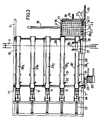
- a jack 18 fixed on the chassis acting transversely to the machine is intended to push the plate 17 in the frame 16 where it is centered by a jack 19 ; in the extension of the frame 16 is disposed a pivotable angle 20 around its middle 20 1 under the action of a jack 21.
- the stroke of the plate 17 is stopped by a contact 22 which puts two pairs of vertical jacks into pneumatic action 23 and 24 intended to block the second and first row 17 2 and 17 1 of the plate 17.
- a longitudinal cylinder 25 is provided for moving the row 17, of the plate 17 towards the rear of the machine when, after time delay, the cylinder 21 will have tilted the angle iron 20 which will break substantially along the joint plants of 17 1 and 17 2 , the connection between these first two rows of clods.
- a flat iron or / angle 26 extending towards the rear of the frame and on which the row 17 1 (or 17 n ) comes to rest under the effect of the jack 25.
- a carrier 27 secured to 'a transverse cable actuator 28 and actuated by two actuators 28 1 makes it possible to transport in various positions, each of which corresponds to the planting element 11 of one of the five conveyors 10, the row 17, (17 n ) broken from of the plate 17.
- Each of the conveyors 10 comprises a continuous conveyor belt 29 driven between two vertical walls 29 'by the pneumatic motor 30 mounted laterally on the chassis, on which the carrier 27 deposits one of the rows 17 n when the place necessary on tape 29 is free.
- a pneumatic passage detector 31 is provided.
- In the vicinity of the upstream end of the strip 29 is arranged 32 for blocking the first root ball of the row 17 n .
- each strip 29 there is mounted a distribution cylinder 33 actuating a finger cylinder 34 which grasps said first root ball and drives it, under appropriate command described below, to the planting station from where it falls, under appropriate control described below, in the furrow dug by the lower part (chute) 12 'of said station.
- a source of compressed air is carried by the chassis and feeds the perforated disc 15, the various cylinders, a main sequencer and secondary sequencers, as well as the contacts necessary for controlling the various cylinders, from the various cylinders. motor 30 and necessary timers.
- the clod board or plate 17 is extracted from its storage tray and put in place, by the operator or serving in the frame 16.
- the operator actuates a two-hand pneumatic safety device M f within reach of his hand which initiates the cycle automatic; the jack 19 centers the clod plate 17 without the frame 16 then the jack 18 pushes the clod plate 17 towards the breaking angle 20 the limit switch contact 22 for supply (fca) is actuated in contact with the first row of clods 17 1 , controls the withdrawal of the jack 18 in the standby position, and the blocking of the clods of the first 171 and the second 17 2 row by the jacks 24 and 23.
- a predetermined time delay actuates the break jack 21; by tilting the angle 20, around its center 20 1 , this jack breaks the first row of clods 171. After breaking the jack 25 pushes the row 17 1 if space is available (fcr) on the receiving angle 26, after withdrawal of the jacks 24 and 23.
- the device returns to the initial position by the retraction of the rod from the jack 25 and the replacement of the jack 21, to receive the second row of clods 17 2 , then 173 and so on until the last row 17 10 where the limit switch Ma + (at the rear of the jack 18) orders the removal of the jack 18 and of the jack 19 to allow the supply of a new clod plate 17 by the operator, and so on, because the separation system is looped in on itself.
- the limit switch Ma + at the rear of the jack 18
- the cable actuator 28 provided with the clod row holder device 27 takes a row 17 1 of clods on the receiving angle 26 if this row has been pushed by the jack 25, otherwise the cable jack 28 is blocked at the end of travel of the jack (fcv) waiting for the angle 26 to be supplied by the jack 25.
- the cable jack 28 will distribute on the first belt 29 1 by actuating the line limit switch 1 (fcl 1) if space is available in the reserve 35 for a complete row of clods: this evaluation of the clod reserve takes place thanks to the pneumatic contact detector 31 which delivers a signal kl.
- an arm jack 33 for gripping by jack jacks 34 of a clod of the row 17 n .
- the arm 38 advances, fingers 34 open, in the direction of a clod.
- the blocking cylinder 32 of the first clod of the reserve then retracts and lets the first clod engage between the fingers 34. It blocks immediately after the penultimate clod.
- the fingers 34 then close and the arm 33 retracts by separating the first root ball from the next by simple traction.
- the finger cylinder 34 then waits for the sowing order, corresponding to row i and the adequate spacing with respect to the previously planted clod, sent from the perforated disc.
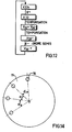
- the staggered spacing and planting control device is obtained from a passage detector associated with the disc 15, perforated with holes and integral with one of the steered wheels and an adequate chosen interval between two successive perforations (angle a ) therefore corresponds to the spacing between two clods successively planted in the ground: if the developed length of the steering wheel is L and if 2n holes are provided in the perforated disc, we obtain n even signals and n odd signals ("staggered "); each of the signals on an even or odd line determines a space L / n on a given even or odd line; L / n is the planting space between two clods: the passage detector of the type known for example under the trade name Compair Climax France delivers its information to a binary divider (single pilot distributor of known type, for example of Marton-Air® ) which outputs its information in staggered rows on a line called of even rank then on another called odd row: it is these orders which control the successive and ordered openings of jacks 34C in the sequence
- the air is led to a negative amplifier 39 supplied by the network and from which the air gains on the one hand the offset sequencer ki with the interposition of a transmission delay 40 and on the other hand a cell OR 37 1 to i inputs debiting in the main sequencer sums ⁇ (fcli).
- FIG. 15 represents the diagram of the sowing orders at the “even” and “odd” planting stations: the perforations 16 of the disc 15 pass through the passage detector 41 (at network pressure); the air coming from 41 passes through a positive amplifier 42 (receiving a network pressure) then a binary divider 43 (receiving a network pressure) from where two lines 44 1 and 44 2 lead respectively to a negative timer 45 giving the signal sowing (at jack 34) on the even lines (the even signal goes to the even sequencer) and to a negative timer 46 giving the sowing signal on odd lines (jack 34, the signal going to the odd sequencer).
- the planting method used is that of opening a continuous furrow; the deposit of the clod 17 on the ground by the chute 12 'with ploughshare 13 realizes the planting of the clod.
- Press wheels 14 complete the work and make it possible to ensure a good connection of the two flanks and of the bottom of the root ball with the soil, conditions required for a good recovery of the plant and the homogeneity of the size of the population of seedlings. the same plot.
- the angle iron 20 returns to the operator supply position, the jack 23 and the motor 30 remain in the state by cutting off the network pressure. Two-hand safety must then be activated again to control the gradual re-pressure of the installation and the restart of the machine.
- the machine operator can stop planting at any time; the motor 30 stops instantaneously, the jack 23 and the angle iron 20 stop automatically after order given respectively by ki and fcr; the machine then restarts automatically at the initiative of the driver.
- the planting machine according to the invention is effectively automatic and that it has simple mechanisms with the advantage of being freed from the normal variations in dimensions of the clod chosen ( ⁇ 20% depending on the three axes) and benefit from the preferential separation plane existing between the clods (a memory of the joint plane, so to speak) which helps to separate them by breakage (rotational movement) or by traction (translational movement) without requiring knives which are rigid and not adjustable in position.
- the machine can be as compact as desired and be made self-propelled for use in the greenhouse.
Landscapes
- Life Sciences & Earth Sciences (AREA)
- Soil Sciences (AREA)
- Environmental Sciences (AREA)
- Soil Working Implements (AREA)
- Transplanting Machines (AREA)
- Hydroponics (AREA)
- Control Of Position, Course, Altitude, Or Attitude Of Moving Bodies (AREA)
- Sowing (AREA)
- Guiding Agricultural Machines (AREA)
Claims (2)
Priority Applications (1)
| Application Number | Priority Date | Filing Date | Title |
|---|---|---|---|
| AT81401378T ATE13239T1 (de) | 1980-09-05 | 1981-09-03 | Automatische pflanzmaschine zum auspflanzen von in erdballen vorgezogenen pflanzen. |
Applications Claiming Priority (2)
| Application Number | Priority Date | Filing Date | Title |
|---|---|---|---|
| FR8019301A FR2492216A1 (fr) | 1980-09-05 | 1980-09-05 | Machine automatique pour la plantation de plants en mottes |
| FR8019301 | 1980-09-05 |
Publications (2)
| Publication Number | Publication Date |
|---|---|
| EP0047700A1 EP0047700A1 (de) | 1982-03-17 |
| EP0047700B1 true EP0047700B1 (de) | 1985-05-15 |
Family
ID=9245712
Family Applications (1)
| Application Number | Title | Priority Date | Filing Date |
|---|---|---|---|
| EP81401378A Expired EP0047700B1 (de) | 1980-09-05 | 1981-09-03 | Automatische Pflanzmaschine zum Auspflanzen von in Erdballen vorgezogenen Pflanzen |
Country Status (6)
| Country | Link |
|---|---|
| EP (1) | EP0047700B1 (de) |
| AT (1) | ATE13239T1 (de) |
| CA (1) | CA1170112A (de) |
| DE (1) | DE3170508D1 (de) |
| ES (1) | ES505200A0 (de) |
| FR (1) | FR2492216A1 (de) |
Families Citing this family (12)
| Publication number | Priority date | Publication date | Assignee | Title |
|---|---|---|---|---|
| FR2531829A1 (fr) * | 1982-08-18 | 1984-02-24 | Beatrix Gerard | Dispositif de distribution semi-automatique pour plantation de plants en mottes |
| FR2577378B1 (fr) * | 1985-02-19 | 1987-10-02 | Raffaello Henri | Planteuse pour plants en mottes |
| NL8601765A (nl) * | 1986-07-07 | 1988-02-01 | Visser S Gravendeel Holding | Verspeeninrichting en -werkwijze. |
| JPH07194208A (ja) * | 1993-12-30 | 1995-08-01 | Yanmar Agricult Equip Co Ltd | 苗移植機の作業台構造 |
| NL1022688C2 (nl) * | 2002-05-07 | 2004-01-06 | Dirk Bruygom | Pootmachine voor het poten van al dan niet ontkiemde planten met een automatisch toevoersysteem. |
| DE102004054905A1 (de) * | 2004-11-14 | 2006-05-24 | SCHWENK, Günther | Entladevorrichtung für Pflanzenbehälter |
| FR2916937B1 (fr) | 2007-06-11 | 2013-02-22 | Rene Budzyn | Procede de fabrication de mottes porteuses de plants et machine a cet effet integrable dans une machine planteuse de plants en motte |
| CN104280335B (zh) * | 2014-10-20 | 2016-08-24 | 江苏大学 | 一种穴盘苗夹钵脱盘力学特性测试装置 |
| CN110972646B (zh) * | 2019-12-03 | 2023-12-05 | 农业农村部南京农业机械化研究所 | 一种适于可降解秧盘的气力式有序抛秧机和抛秧方法 |
| CN112166764B (zh) * | 2020-09-30 | 2021-08-03 | 青岛农业大学 | 一种全自动移栽机 |
| CN113277407B (zh) * | 2021-03-30 | 2022-11-15 | 广州明森合兴科技有限公司 | 一种底码自动安装设备及方法 |
| CN117643215B (zh) * | 2024-01-26 | 2024-11-29 | 安徽农业大学 | 一种线式供苗的全自动甘薯移栽机 |
Family Cites Families (4)
| Publication number | Priority date | Publication date | Assignee | Title |
|---|---|---|---|---|
| DE849197C (de) * | 1948-10-02 | 1952-09-11 | Beche & Grohs Ges Mit Beschrae | Pflanzmaschine zum Auspflanzen von in Erdballen vorgezogenen Gemuesepflanzen od. dgl. |
| FR1408269A (fr) * | 1964-06-30 | 1965-08-13 | Cie D Ingenieurs Et Technicien | Machine à planter automatique |
| NL6807876A (de) * | 1967-06-06 | 1968-12-09 | ||
| DE2963216D1 (en) * | 1979-04-06 | 1982-08-19 | Rene Budzyn | Device for planting plants in clods or pots |
-
1980
- 1980-09-05 FR FR8019301A patent/FR2492216A1/fr active Granted
-
1981
- 1981-09-03 AT AT81401378T patent/ATE13239T1/de active
- 1981-09-03 EP EP81401378A patent/EP0047700B1/de not_active Expired
- 1981-09-03 DE DE8181401378T patent/DE3170508D1/de not_active Expired
- 1981-09-04 CA CA000385243A patent/CA1170112A/fr not_active Expired
- 1981-09-04 ES ES505200A patent/ES505200A0/es active Granted
Also Published As
| Publication number | Publication date |
|---|---|
| FR2492216A1 (fr) | 1982-04-23 |
| CA1170112A (fr) | 1984-07-03 |
| ES8206135A1 (es) | 1982-08-16 |
| FR2492216B1 (de) | 1984-05-18 |
| DE3170508D1 (en) | 1985-06-20 |
| EP0047700A1 (de) | 1982-03-17 |
| ATE13239T1 (de) | 1985-06-15 |
| ES505200A0 (es) | 1982-08-16 |
Similar Documents
| Publication | Publication Date | Title |
|---|---|---|
| EP0047700B1 (de) | Automatische Pflanzmaschine zum Auspflanzen von in Erdballen vorgezogenen Pflanzen | |
| EP0145527B1 (de) | Wasserstrahlschneidvorrichtung für Bänder | |
| CH636571A5 (fr) | Installation de distribution de produits a des postes de travail. | |
| FR2608890A1 (fr) | Tondeuse du type a deplacer devant soi | |
| WO2004095906A1 (en) | A method and apparatus for transporting seedlings in a planting machine | |
| EP1222845B1 (de) | Verfahren zum Trennen eckiger Setzlinge, Gerät zum Ausführen des Verfahrens und Pflanzmaschine mit einem solchen Gerät zum Pflanzen von Setzlingen | |
| FR2778647A1 (fr) | Mecanisme d'orientation et de distribution automatique de pieces | |
| JP3798554B2 (ja) | 茎幹処理装置 | |
| EP0539324B1 (de) | Ausrichtungsverfahren und -vorrichtung für einen Ausgabetrichter, insbesondere zum Ausgaben von Zigaretten | |
| FR2542153A1 (fr) | Dispositif et procede de transfert de composants electroniques pour machine d'insertion dans des circuits imprimes | |
| JP6870632B2 (ja) | 苗移植機 | |
| FR2801168A1 (fr) | Procede pour separer des mottes cubiques, dispositif pour la mise en oeuvre du procede et machine de plantation de plants en mottes comportant un tel dispositif | |
| JP6222471B2 (ja) | 根菜類収穫機 | |
| WO1994019970A1 (fr) | Procede, dispositifs et machine de decorticage de vegetaux | |
| FR3121320A1 (fr) | Machine agricole, pour la récolte et le traitement de radis | |
| FR2577754A1 (fr) | Procede et dispositif de terrage en bout de rang pour semoir de graines sous paillage | |
| FR2506557A1 (fr) | Procede pour planter en rangs et a intervalles reguliers et machine pour la mise en oeuvre dudit procede | |
| BE1003266A5 (fr) | Methode et machine de plantation automatique de plantules. | |
| FR2471342A1 (fr) | Dispositif encolleur pour machines de fixation de filtres pour cigarettes | |
| EP0113286B1 (de) | Rütteltisch zur Aufnahme von blattförmigem Gut, insbesondere von Papierbogenstapeln | |
| FR2642938A1 (fr) | Dispositif de distribution et d'espacement automatiques de batonnets ou piques pour machine a brochettes | |
| FR2738988A1 (fr) | Machine automatique permettant de realiser le depotage et rempotage de plants et dispositif permettant la manutention desdits plants utilisables sur une telle machine | |
| NL1022688C2 (nl) | Pootmachine voor het poten van al dan niet ontkiemde planten met een automatisch toevoersysteem. | |
| FR2759865A1 (fr) | Perfectionnement aux procedes et aux installations de fabrication automatique de sandwiches du genre gouters fourres | |
| CH256411A (fr) | Machine à planter, notamment les pommes de terre. |
Legal Events
| Date | Code | Title | Description |
|---|---|---|---|
| PUAI | Public reference made under article 153(3) epc to a published international application that has entered the european phase |
Free format text: ORIGINAL CODE: 0009012 |
|
| AK | Designated contracting states |
Designated state(s): AT BE CH DE GB IT LU NL SE |
|
| TCAT | At: translation of patent claims filed | ||
| TCNL | Nl: translation of patent claims filed | ||
| ITCL | It: translation for ep claims filed |
Representative=s name: STUDIO TORTA SOCIETA' SEMPLICE |
|
| 17P | Request for examination filed |
Effective date: 19820804 |
|
| ITF | It: translation for a ep patent filed | ||
| GRAA | (expected) grant |
Free format text: ORIGINAL CODE: 0009210 |
|
| AK | Designated contracting states |
Designated state(s): AT BE CH DE GB IT LI LU NL SE |
|
| PG25 | Lapsed in a contracting state [announced via postgrant information from national office to epo] |
Ref country code: AT Effective date: 19850515 |
|
| REF | Corresponds to: |
Ref document number: 13239 Country of ref document: AT Date of ref document: 19850615 Kind code of ref document: T |
|
| PG25 | Lapsed in a contracting state [announced via postgrant information from national office to epo] |
Ref country code: SE Effective date: 19850530 |
|
| REF | Corresponds to: |
Ref document number: 3170508 Country of ref document: DE Date of ref document: 19850620 |
|
| PG25 | Lapsed in a contracting state [announced via postgrant information from national office to epo] |
Ref country code: LU Free format text: LAPSE BECAUSE OF NON-PAYMENT OF DUE FEES Effective date: 19850930 Ref country code: LI Effective date: 19850930 Ref country code: CH Effective date: 19850930 Ref country code: BE Effective date: 19850930 |
|
| PLBE | No opposition filed within time limit |
Free format text: ORIGINAL CODE: 0009261 |
|
| STAA | Information on the status of an ep patent application or granted ep patent |
Free format text: STATUS: NO OPPOSITION FILED WITHIN TIME LIMIT |
|
| BERE | Be: lapsed |
Owner name: ETS REGERO Effective date: 19850903 |
|
| 26N | No opposition filed | ||
| REG | Reference to a national code |
Ref country code: CH Ref legal event code: PL |
|
| PGFP | Annual fee paid to national office [announced via postgrant information from national office to epo] |
Ref country code: GB Payment date: 19910830 Year of fee payment: 11 |
|
| ITTA | It: last paid annual fee | ||
| PGFP | Annual fee paid to national office [announced via postgrant information from national office to epo] |
Ref country code: NL Payment date: 19910930 Year of fee payment: 11 |
|
| PGFP | Annual fee paid to national office [announced via postgrant information from national office to epo] |
Ref country code: DE Payment date: 19911018 Year of fee payment: 11 |
|
| PG25 | Lapsed in a contracting state [announced via postgrant information from national office to epo] |
Ref country code: GB Effective date: 19920903 |
|
| PG25 | Lapsed in a contracting state [announced via postgrant information from national office to epo] |
Ref country code: NL Effective date: 19930401 |
|
| GBPC | Gb: european patent ceased through non-payment of renewal fee |
Effective date: 19920903 |
|
| NLV4 | Nl: lapsed or anulled due to non-payment of the annual fee | ||
| PG25 | Lapsed in a contracting state [announced via postgrant information from national office to epo] |
Ref country code: DE Effective date: 19930602 |