EP0047864A2 - Befestigungsvorrichtung für längliche Teile, wie z.B. Kabel - Google Patents
Befestigungsvorrichtung für längliche Teile, wie z.B. Kabel Download PDFInfo
- Publication number
- EP0047864A2 EP0047864A2 EP81106322A EP81106322A EP0047864A2 EP 0047864 A2 EP0047864 A2 EP 0047864A2 EP 81106322 A EP81106322 A EP 81106322A EP 81106322 A EP81106322 A EP 81106322A EP 0047864 A2 EP0047864 A2 EP 0047864A2
- Authority
- EP
- European Patent Office
- Prior art keywords
- base plate
- holder
- bent
- piece
- held
- Prior art date
- Legal status (The legal status is an assumption and is not a legal conclusion. Google has not performed a legal analysis and makes no representation as to the accuracy of the status listed.)
- Granted
Links
Images
Classifications
-
- F—MECHANICAL ENGINEERING; LIGHTING; HEATING; WEAPONS; BLASTING
- F16—ENGINEERING ELEMENTS AND UNITS; GENERAL MEASURES FOR PRODUCING AND MAINTAINING EFFECTIVE FUNCTIONING OF MACHINES OR INSTALLATIONS; THERMAL INSULATION IN GENERAL
- F16L—PIPES; JOINTS OR FITTINGS FOR PIPES; SUPPORTS FOR PIPES, CABLES OR PROTECTIVE TUBING; MEANS FOR THERMAL INSULATION IN GENERAL
- F16L3/00—Supports for pipes, cables or protective tubing, e.g. hangers, holders, clamps, cleats, clips, brackets
- F16L3/08—Supports for pipes, cables or protective tubing, e.g. hangers, holders, clamps, cleats, clips, brackets substantially surrounding the pipe, cable or protective tubing
- F16L3/12—Supports for pipes, cables or protective tubing, e.g. hangers, holders, clamps, cleats, clips, brackets substantially surrounding the pipe, cable or protective tubing comprising a member substantially surrounding the pipe, cable or protective tubing
- F16L3/13—Supports for pipes, cables or protective tubing, e.g. hangers, holders, clamps, cleats, clips, brackets substantially surrounding the pipe, cable or protective tubing comprising a member substantially surrounding the pipe, cable or protective tubing and engaging it by snap action
-
- F—MECHANICAL ENGINEERING; LIGHTING; HEATING; WEAPONS; BLASTING
- F16—ENGINEERING ELEMENTS AND UNITS; GENERAL MEASURES FOR PRODUCING AND MAINTAINING EFFECTIVE FUNCTIONING OF MACHINES OR INSTALLATIONS; THERMAL INSULATION IN GENERAL
- F16L—PIPES; JOINTS OR FITTINGS FOR PIPES; SUPPORTS FOR PIPES, CABLES OR PROTECTIVE TUBING; MEANS FOR THERMAL INSULATION IN GENERAL
- F16L3/00—Supports for pipes, cables or protective tubing, e.g. hangers, holders, clamps, cleats, clips, brackets
- F16L3/24—Supports for pipes, cables or protective tubing, e.g. hangers, holders, clamps, cleats, clips, brackets with special member for attachment to profiled girders
-
- F—MECHANICAL ENGINEERING; LIGHTING; HEATING; WEAPONS; BLASTING
- F16—ENGINEERING ELEMENTS AND UNITS; GENERAL MEASURES FOR PRODUCING AND MAINTAINING EFFECTIVE FUNCTIONING OF MACHINES OR INSTALLATIONS; THERMAL INSULATION IN GENERAL
- F16L—PIPES; JOINTS OR FITTINGS FOR PIPES; SUPPORTS FOR PIPES, CABLES OR PROTECTIVE TUBING; MEANS FOR THERMAL INSULATION IN GENERAL
- F16L3/00—Supports for pipes, cables or protective tubing, e.g. hangers, holders, clamps, cleats, clips, brackets
- F16L3/24—Supports for pipes, cables or protective tubing, e.g. hangers, holders, clamps, cleats, clips, brackets with special member for attachment to profiled girders
- F16L3/243—Supports for pipes, cables or protective tubing, e.g. hangers, holders, clamps, cleats, clips, brackets with special member for attachment to profiled girders the special member being inserted in the profiled girder
Definitions
- This invention relates to a holder suitable for disposing or mounting various lengthy articles or members at desired locations.
- Electric cords, electric cables or the harness thereof are usually disposed at inconspicuous locations such as the upper portions of walls, ceilings or the corners thereof and are held so that the important points thereof do not shift.
- Holders must originally satisfy various requirements including their ability to hold members to be held such as harness or the like so that they do not unreasonably shift, a good working property ensured in any narrow place and permitting ready mounting or dismounting of the members to be held, a holding function which will not cause damages to the members to be held, and the possibility that a single holder can accommodate various sizes of members to be held.
- such holders must satisfy universal requirements such as simplicity of structure, ease of manufacture and low cost of manufacture.
- resilient metal fittings having a U-shaped or like cross section adapted to be attached to a wall surface and into which the members to be held are forced so as to be held satisfy the requirements concerning the structure, manufacture and cost, whereas if the resiliency (spring force) of the holders is intensified, the above-described operation of forcing the members to be held into the holders becomes difficult to carry out and may also damage the members to be held and conversely, if the resiliency of the holders is weakened, there will occur a problem that the members to be held which have been fitted into the interior of the holders shift. In addition, a single holder of such type cannot accommodate various sizes of members to be held.
- the holder of the present invention mainly comprises a base plate having a hooking projection on the inner side of one end thereof, a bent piece bent inwardly of the base plate and integrally connected to the other end of the base plate, and pressing piece folded between the bent piece and the base plate and integrally connected to the end of the bent piece, a holding space being formed between the base plate and the pressing piece.
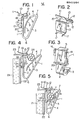
- reference numeral 1 designates a holder made of plastic.
- the holder 1 may alternatively be made of a resilient metal in some cases.
- the holder 1 comprises chiefly a base plate 2, a bent piece 3 and a pressing piece 4.
- the base plate 2 has a hooking projection 5 on the inner side of one end thereof and the bent piece 3 is integrally connected to the base plate 2 through a bent portion 6.
- the base plate 2 and the bent piece 3 form therebetween a V-shaped angle smaller than 90°.
- the pressing piece 4 is integrally connected to the end of the bent piece 3 through a bent portion 7, and is folded into between the base plate 2 and the bent piece 3.
- a holding space 8 is formed between the base plate 2 and the pressing piece 4, and in the pressing piece 4, as shown, a plurality of hinge portions 9, 9, 9 for making the pressing piece 4 bendable are formed by concave grooves.
- the holder 1 may be attached to a desired location by securing the base plate 2 by means of screws or an adhesive agent, but in the illustrated embodiment, as an example, a fitting 10 of metal which will hereinafter be described is combined with the holder 1.
- the fitting 10 shown in Figure 2 comprises a mounting portion 12 having an upwardly warped end portion 11 and bend into an inverted U-shape, a flat plate portion 13 extending downwardly from the mounting portion 12, and an abutting portion 14 outwardly bent from the lower end of the flat plate portion 13.
- the mounting portion 12 is formed with detent pieces 15, 15, the flat plate portion 13 is formed with a hooking aperture 16, and the abutting portion 14 is formed with penetrating pieces 17, 17.
- the base plate 2 of the holder 1 shown in Figure 3 has, on the opposite side edges of the outer surface thereof, a pair of slide fitting grooves 18, 18 corresponding to the width of the flat plate portion 13, and a hooking projection 19 corresponding to the hooking aperture 16 and a receiving portion 20 accommodating with the abutting portion 14 are provided on the outer surface of the base plate 2.
- the holder 1 with the fitting 10 thus combined therewith will be attached to the interior of an automotive vehicle, for example.
- reference numeral 21 designates an adiabatic, sound-intercepting insulator lying at the boundary between an engine room and a passenger compartment
- reference numeral 22 denotes a decorative plate secured to that side of the insulator 21 which is adjacent to the passenger compartment
- reference numeral 23 designates a dash panel.
- the fitting 10 may be mounted in position by causing the mounting portion 12 having the detent pieces 15, 15 to hold the dash panel 23 and causing the penetrating pieces 17, 17 of the abutting portion 14 to penetrate into the decorative plate 22, and the holder 1 may be secured in position through the intermediary of the fitting 10.
- a plurality of holders 1 are mounted at predetermined intervals in the manner described above, and a member 24 to be held such as harness or the like is held by being received in the holding space 8 within each of such holders 1.
- the pressing piece 4 is bent and deformed by virtue of the hinge portions 9, 9, 9 so as to cover part of the outer periphery of the member 24 to be held, thus enhancing the holding effect.
- the base plate has a hooking projection on the inner side of one end thereof and an inwardly bent piece is integrally connected to the other end of the base plate and a pressing piece folded into between the bent piece and the base plate is integrally connected to the end of the bent piece so as to form a holding space between the base plate and the pressing piece, when a member to be held is inserted into or removed from the holding space of the holder, the bent configuration by the base plate, the bent piece and the pressing piece may be simply deformed and, even though the holder has been mounted at a narrow place, the above-described operation can be simply accomplished and the working property can be secured sufficiently.
- the member to be held in the holding space is held by the base plate, its hooking projection and the pressing piece and in this condition, a two-stage spring force provided by the two bent portions acts to prevent the member being held from shifting unreasonably and moreover, the member 24 being held which is in a resiliently held condition may be relieved of any influence of vibration or extraneous impact and can never be damaged.
- the holding space of the holder has its internal volume contractible or expansible by variations in the angle of bent portion between the base plate and the bent piece and the angle of bent portion between the bent piece and the pressing piece. Accordingly, the holding space can hold therein members of various sizes to be held within its tolerance and as a result, a single holder can accommodate members of various sizes to be held.
- the holder which comprises a relative bent structure of base plate, bent piece and pressing piece can be simply manufactured either by plastic molding or by metal molding and offers no problem of increased cost or complicated structure.
- the hinge portions formed in the pressing piece can enhance the holding effect.
Landscapes
- Engineering & Computer Science (AREA)
- General Engineering & Computer Science (AREA)
- Mechanical Engineering (AREA)
- Installation Of Indoor Wiring (AREA)
- Supports For Pipes And Cables (AREA)
Applications Claiming Priority (2)
| Application Number | Priority Date | Filing Date | Title |
|---|---|---|---|
| JP115779/80 | 1980-08-15 | ||
| JP11577980A JPS5665067A (en) | 1979-08-22 | 1980-08-22 | Adhesive |
Publications (3)
| Publication Number | Publication Date |
|---|---|
| EP0047864A2 true EP0047864A2 (de) | 1982-03-24 |
| EP0047864A3 EP0047864A3 (en) | 1982-08-04 |
| EP0047864B1 EP0047864B1 (de) | 1984-11-14 |
Family
ID=14670841
Family Applications (1)
| Application Number | Title | Priority Date | Filing Date |
|---|---|---|---|
| EP81106322A Expired EP0047864B1 (de) | 1980-08-15 | 1981-08-13 | Befestigungsvorrichtung für längliche Teile, wie z.B. Kabel |
Country Status (2)
| Country | Link |
|---|---|
| US (1) | US4438894A (de) |
| EP (1) | EP0047864B1 (de) |
Cited By (4)
| Publication number | Priority date | Publication date | Assignee | Title |
|---|---|---|---|---|
| US4843707A (en) * | 1987-08-19 | 1989-07-04 | Sanders Associates, Inc. | Cable retention system |
| FR2653183A1 (fr) * | 1989-10-12 | 1991-04-19 | Rapid Sa | Attache pour la fixation d'un element par exemple tubulaire sur une paroi quelconque. |
| EP1837571A3 (de) * | 2006-03-24 | 2015-07-22 | icotek projekt GmbH & Co.KG | Befestigungsvorrichtung |
| FR3106379A1 (fr) * | 2020-01-17 | 2021-07-23 | Psa Automobiles Sa | Agrafe pince ayant une interface déportée |
Families Citing this family (6)
| Publication number | Priority date | Publication date | Assignee | Title |
|---|---|---|---|---|
| US4742979A (en) * | 1987-02-19 | 1988-05-10 | Syversten William O | Cable hanger |
| US6047930A (en) * | 1998-07-29 | 2000-04-11 | Hendrix Wire & Cable, Inc. | Aerial cable retainer with fulcrum point |
| US6945501B2 (en) * | 2003-09-16 | 2005-09-20 | Thompson William J | Communication cable support structure and apparatus and method for making |
| ITGE20060079A1 (it) * | 2006-08-02 | 2008-02-03 | Mares Spa | Dispositivo di agganciamento rapido e di sospensione snodabile dei tubi respiratori alla cinghietta delle maschere per attivita' subacquea. |
| US20090101763A1 (en) * | 2007-10-22 | 2009-04-23 | David Newcomb | Cable Hanger |
| US20110139950A1 (en) * | 2009-12-15 | 2011-06-16 | Plantronics, Inc. | Retention Clip with Two Points of Contact |
Family Cites Families (9)
| Publication number | Priority date | Publication date | Assignee | Title |
|---|---|---|---|---|
| US2385209A (en) * | 1943-04-14 | 1945-09-18 | Edward F Joyce | Clamp |
| US2683578A (en) * | 1950-08-24 | 1954-07-13 | Ford Motor Co | High-tension wiring harness |
| US2990150A (en) * | 1959-03-06 | 1961-06-27 | Robert M Weigel | Goffered wire clip bank |
| US2972461A (en) * | 1959-04-27 | 1961-02-21 | Robert L Brown | Hose clip |
| US3163712A (en) * | 1960-01-26 | 1964-12-29 | United Carr Inc | Wiring clip having a stud engagement means |
| GB1022820A (en) * | 1963-11-12 | 1966-03-16 | Albert Victor Raymond | Improvements in and relating to fasteners for attaching a cable or cables to an apertured support |
| US3423055A (en) * | 1966-10-24 | 1969-01-21 | Illinois Tool Works | Plastic fastener and cable support |
| US3568964A (en) * | 1968-12-09 | 1971-03-09 | Gavin Instr Inc | Cable mounting |
| US4083523A (en) * | 1976-05-14 | 1978-04-11 | Fisher John L | Fastening device |
-
1981
- 1981-08-10 US US06/291,290 patent/US4438894A/en not_active Expired - Fee Related
- 1981-08-13 EP EP81106322A patent/EP0047864B1/de not_active Expired
Cited By (4)
| Publication number | Priority date | Publication date | Assignee | Title |
|---|---|---|---|---|
| US4843707A (en) * | 1987-08-19 | 1989-07-04 | Sanders Associates, Inc. | Cable retention system |
| FR2653183A1 (fr) * | 1989-10-12 | 1991-04-19 | Rapid Sa | Attache pour la fixation d'un element par exemple tubulaire sur une paroi quelconque. |
| EP1837571A3 (de) * | 2006-03-24 | 2015-07-22 | icotek projekt GmbH & Co.KG | Befestigungsvorrichtung |
| FR3106379A1 (fr) * | 2020-01-17 | 2021-07-23 | Psa Automobiles Sa | Agrafe pince ayant une interface déportée |
Also Published As
| Publication number | Publication date |
|---|---|
| EP0047864B1 (de) | 1984-11-14 |
| EP0047864A3 (en) | 1982-08-04 |
| US4438894A (en) | 1984-03-27 |
Similar Documents
| Publication | Publication Date | Title |
|---|---|---|
| US5005792A (en) | Bracket for mounting an electrical switchbox on a wall stud | |
| US3842565A (en) | Resilient buffer assembly | |
| US4913384A (en) | Mounting structure for cart-mount devices | |
| EP1653092A1 (de) | Fahrzeugspiegelanordnung | |
| US4438894A (en) | Holder | |
| CN106608227B (zh) | 用倒钩固定在支架上的紧固夹 | |
| US4086679A (en) | Carpet retainers | |
| US5890831A (en) | Engaging mechanism and a holder using therefor | |
| US5538210A (en) | Fastener for fixing longitudinal members | |
| US5803758A (en) | Switch box mounting structure | |
| JP2002227809A (ja) | トリムボード等の取付部材を車体等の被取付部材に固定するクリップ | |
| US4947290A (en) | Rail mounting device for an electrical equipment | |
| EP3444485B1 (de) | Befestigungselement und befestigungselementeanordnung | |
| JP3269009B2 (ja) | ゴム製部品の取り付け構造 | |
| EP1238856B1 (de) | Innenraumleuchte für Fahrzeuge | |
| US7118412B2 (en) | Apparatus for fixing connector for airbag module | |
| US4326689A (en) | Mount for a housing which is releasably fastened to a wall | |
| JPH07174127A (ja) | 保持具 | |
| US4723748A (en) | Article holder | |
| JPH0631261Y2 (ja) | 棒状物の取付板への取付構造 | |
| US4490893A (en) | Fastening device for holding construction or functional parts on cover plates | |
| KR100204889B1 (ko) | 잭핸들 고정용 클립 | |
| JPH0441706Y2 (de) | ||
| JPH0532360Y2 (de) | ||
| JPH09226466A (ja) | リヤシェルフの保持構造 |
Legal Events
| Date | Code | Title | Description |
|---|---|---|---|
| PUAI | Public reference made under article 153(3) epc to a published international application that has entered the european phase |
Free format text: ORIGINAL CODE: 0009012 |
|
| AK | Designated contracting states |
Kind code of ref document: A2 Designated state(s): DE FR GB IT |
|
| 17P | Request for examination filed |
Effective date: 19820309 |
|
| PUAL | Search report despatched |
Free format text: ORIGINAL CODE: 0009013 |
|
| AK | Designated contracting states |
Kind code of ref document: A3 Designated state(s): DE FR GB IT |
|
| ITF | It: translation for a ep patent filed | ||
| GRAA | (expected) grant |
Free format text: ORIGINAL CODE: 0009210 |
|
| AK | Designated contracting states |
Kind code of ref document: B1 Designated state(s): DE FR GB IT |
|
| REF | Corresponds to: |
Ref document number: 3167202 Country of ref document: DE Date of ref document: 19841220 |
|
| ET | Fr: translation filed | ||
| RAP2 | Party data changed (patent owner data changed or rights of a patent transferred) |
Owner name: KATO HATSUJYO KAISHA LTD. Owner name: NISSAN MOTOR CO., LTD. |
|
| PLBE | No opposition filed within time limit |
Free format text: ORIGINAL CODE: 0009261 |
|
| STAA | Information on the status of an ep patent application or granted ep patent |
Free format text: STATUS: NO OPPOSITION FILED WITHIN TIME LIMIT |
|
| 26N | No opposition filed | ||
| GBPC | Gb: european patent ceased through non-payment of renewal fee | ||
| PG25 | Lapsed in a contracting state [announced via postgrant information from national office to epo] |
Ref country code: FR Free format text: LAPSE BECAUSE OF NON-PAYMENT OF DUE FEES Effective date: 19870430 |
|
| PG25 | Lapsed in a contracting state [announced via postgrant information from national office to epo] |
Ref country code: DE Effective date: 19870501 |
|
| REG | Reference to a national code |
Ref country code: FR Ref legal event code: ST |
|
| PG25 | Lapsed in a contracting state [announced via postgrant information from national office to epo] |
Ref country code: GB Effective date: 19881118 |