EP0048068A1 - Verfahren zum Bekämpfen von Zielen und Projektile oder Raketen zum Durchführen des Verfahrens - Google Patents
Verfahren zum Bekämpfen von Zielen und Projektile oder Raketen zum Durchführen des Verfahrens Download PDFInfo
- Publication number
- EP0048068A1 EP0048068A1 EP81201019A EP81201019A EP0048068A1 EP 0048068 A1 EP0048068 A1 EP 0048068A1 EP 81201019 A EP81201019 A EP 81201019A EP 81201019 A EP81201019 A EP 81201019A EP 0048068 A1 EP0048068 A1 EP 0048068A1
- Authority
- EP
- European Patent Office
- Prior art keywords
- target
- projectile
- signal
- trajectory
- projectiles
- Prior art date
- Legal status (The legal status is an assumption and is not a legal conclusion. Google has not performed a legal analysis and makes no representation as to the accuracy of the status listed.)
- Granted
Links
- 238000000034 method Methods 0.000 title claims description 10
- 238000001514 detection method Methods 0.000 claims abstract description 14
- 238000010304 firing Methods 0.000 claims abstract description 7
- 230000005670 electromagnetic radiation Effects 0.000 claims abstract description 6
- 239000002360 explosive Substances 0.000 claims abstract description 3
- 230000005540 biological transmission Effects 0.000 claims description 17
- 230000001105 regulatory effect Effects 0.000 claims description 5
- 238000013459 approach Methods 0.000 claims description 4
- 230000000977 initiatory effect Effects 0.000 claims description 4
- 230000000694 effects Effects 0.000 claims description 2
- 230000000063 preceeding effect Effects 0.000 abstract 1
- 230000008054 signal transmission Effects 0.000 abstract 1
- 230000005855 radiation Effects 0.000 description 15
- 230000006870 function Effects 0.000 description 6
- 238000001208 nuclear magnetic resonance pulse sequence Methods 0.000 description 6
- 230000033228 biological regulation Effects 0.000 description 5
- 238000010586 diagram Methods 0.000 description 5
- 238000005286 illumination Methods 0.000 description 5
- 239000008186 active pharmaceutical agent Substances 0.000 description 3
- 230000005284 excitation Effects 0.000 description 3
- 230000004913 activation Effects 0.000 description 2
- 230000001276 controlling effect Effects 0.000 description 2
- 230000006641 stabilisation Effects 0.000 description 2
- 235000015842 Hesperis Nutrition 0.000 description 1
- 235000012633 Iberis amara Nutrition 0.000 description 1
- 108010060499 acharan sulfate lyase 1 Proteins 0.000 description 1
- 108010060486 acharan sulfate lyase 2 Proteins 0.000 description 1
- 238000010276 construction Methods 0.000 description 1
- 230000004069 differentiation Effects 0.000 description 1
- 230000008034 disappearance Effects 0.000 description 1
- 238000000605 extraction Methods 0.000 description 1
- 238000001914 filtration Methods 0.000 description 1
- 238000004519 manufacturing process Methods 0.000 description 1
- 230000035945 sensitivity Effects 0.000 description 1
- 230000001360 synchronised effect Effects 0.000 description 1
- 230000001702 transmitter Effects 0.000 description 1
Images

Classifications
-
- F—MECHANICAL ENGINEERING; LIGHTING; HEATING; WEAPONS; BLASTING
- F41—WEAPONS
- F41G—WEAPON SIGHTS; AIMING
- F41G7/00—Direction control systems for self-propelled missiles
- F41G7/20—Direction control systems for self-propelled missiles based on continuous observation of target position
- F41G7/22—Homing guidance systems
- F41G7/2246—Active homing systems, i.e. comprising both a transmitter and a receiver
-
- F—MECHANICAL ENGINEERING; LIGHTING; HEATING; WEAPONS; BLASTING
- F41—WEAPONS
- F41G—WEAPON SIGHTS; AIMING
- F41G7/00—Direction control systems for self-propelled missiles
-
- F—MECHANICAL ENGINEERING; LIGHTING; HEATING; WEAPONS; BLASTING
- F41—WEAPONS
- F41G—WEAPON SIGHTS; AIMING
- F41G7/00—Direction control systems for self-propelled missiles
- F41G7/20—Direction control systems for self-propelled missiles based on continuous observation of target position
-
- F—MECHANICAL ENGINEERING; LIGHTING; HEATING; WEAPONS; BLASTING
- F41—WEAPONS
- F41G—WEAPON SIGHTS; AIMING
- F41G7/00—Direction control systems for self-propelled missiles
- F41G7/20—Direction control systems for self-propelled missiles based on continuous observation of target position
- F41G7/22—Homing guidance systems
- F41G7/226—Semi-active homing systems, i.e. comprising a receiver and involving auxiliary illuminating means, e.g. using auxiliary guiding missiles
-
- F—MECHANICAL ENGINEERING; LIGHTING; HEATING; WEAPONS; BLASTING
- F41—WEAPONS
- F41G—WEAPON SIGHTS; AIMING
- F41G7/00—Direction control systems for self-propelled missiles
- F41G7/20—Direction control systems for self-propelled missiles based on continuous observation of target position
- F41G7/22—Homing guidance systems
- F41G7/2273—Homing guidance systems characterised by the type of waves
- F41G7/2286—Homing guidance systems characterised by the type of waves using radio waves
-
- F—MECHANICAL ENGINEERING; LIGHTING; HEATING; WEAPONS; BLASTING
- F41—WEAPONS
- F41G—WEAPON SIGHTS; AIMING
- F41G7/00—Direction control systems for self-propelled missiles
- F41G7/20—Direction control systems for self-propelled missiles based on continuous observation of target position
- F41G7/22—Homing guidance systems
- F41G7/2273—Homing guidance systems characterised by the type of waves
- F41G7/2293—Homing guidance systems characterised by the type of waves using electromagnetic waves other than radio waves
Definitions
- the invention relates to a method for combatting of targets by firing of explosive projectiles provided with target tracking devices towards the target in order to, after discovery of a target, ensure automatic guidance of the projectile against the target, the said target tracking device operating with reception and detection of electromagnetic radiation in order to produce an error signal indicating a deviation between the projectile trajectory and a trajectory passing through the target, which error signal is adapted to influence guiding means on the projectile in order to bring the deviation to approach zero.
- the object of the invention is to propose a simple, cheap and effective solution of the said problems, which is achieved thereby that, in burst of projectiles, at least one projectile is fired having transmitter means which are initiated by means for detection of a target, which transmitter means are adapted, after detection of target, to transmit a signal indicating the position of the target relative to the projectile trajectory to another projectile (projectiles) present in the burst for producing a trajectory correction in the other projectile with air. of the position indicating signal from the said first projectile.
- the transmitter means are preferably initiated at the end of the trajectory of the projectile towards the target for giving a position indication to the following projectiles, in first hand the closest following projectile.
- a projectile which approaches a target and has detected this target, thus transmits information about the position of the target relative to the projectile to another, for example the closest following projectile, and in this projectile a correction of the projectile trajectory is effected by the aid of the received position information in combination with the information about the position of the transmitting projectile, which is available in the own target tracking device, so that the projectile is guided to follow a more correct trajectory towards the target.
- the target tracking device in the other projectile for example the next following projectile, thus does not need to discover the target itself during this correction phase but utilizes the detector in the foregoing projectile for its correction.
- the transmitting projectile When the transmitting projectile has hit the ground or disappeared on the side of the target the other projectile, for example next following projectile, continues in its corrected trajectory and tries in this phase to discover the target on itw own.
- the target in a later part of this phase is discovered by the aid of its own radiation of the target final guidance towards the target is effected for obtaining a hit, if possible.
- all projectiles can be provided with transmitter means which are made effective at the end of the projectile trajectory for delivering target information to the following projectile.
- transmitter means which are made effective at the end of the projectile trajectory for delivering target information to the following projectile.
- a projectile or a missile for carrying out the method according to the invention adapted to cooperate with a projectile having a target tracking device comprising a receiver and detector device for reception and detection of electromagnetic radiation from a target and a signal processing unit for deriving a target signal containing information about the position of the target from the detected signal and to generate an error signal therefrom, which error signal indicates the deviation of the projectile trajectory from a trajectory passing through the target, which error signal is adapted to influence guiding means on the projectile for infl.uencing the projectile trajectory in such a direction, that the error signal is regulated to zero, can be characterized thereby, that it furthermore comprises transmitter means with modulator or coding means which are controlled by a detector adapted to detect a target and to determine the position of the target relative to the own projectile for bringing the transmitter means to transmit a modulated signal after detection of a target, which signal indicates the position of the target, and that in the target tracking device in the cooperating projectile there are means for demodulation or decoding of the said position
- the projectile has both a target tracking device and transmitter means for position indicative transmission
- the detector device for initiating the said transmitter means can be the same detector as that included in the tracking device.
- the target tracking device has suitably two reception channels, one for reception of the said coded position indicating signal and one for reception of the own radiation of the target or radiation reflected from the target, and furthermore switching means for automatic switching between the said first reception channel, when signal is received from another projectile, and the second reception channel when the said signal has disappeared.
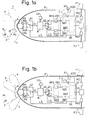
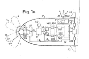
- FIG. 1b and 1c show a simplified block diagram for a projectile provided with a radiometric target tracking device operating according to the invention in different stages of the trajectory
- figure 2 shows a detailed block diagram for a projectile provided with a radar target tracking device of monopulse type, which is modified in accordance with the invention
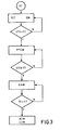
- figure 3 shows a flow diagram for illustrating the time sequence of events in the arrangement according to figure 2.
- figure 1 The broad principle according to the invention is illustrated in figure 1 by showing a projectile with a target tracking device operating in accordance with the invention in three different positions of the trajectory.
- the aim with these figures is not to show a detailed construction of a target tracking device and this target tracking device is therefore shown very schematically with details only in an extent to enable an understanding of theprinciples according to the invention.
- All projectiles are assumed to be mutually identical and provided both with tracking device and transmitter means for transmission of a code signal indicating the position of the target at the end of the trajectory.
- the projectiles are fired at so short intervals that, when a projectile has detected a target and transmits a position code signal, the closest following projectile is situated at suitable distance for receiving the transmitted position code signal, for example 2-3 km from the target.
- figure 1a shows the condition in the projectile when it is situated at a large distance from a target, when a foregoing projectile has discovered the target and transmits a position code signal
- figure 1b shows the condition in the projectile when the position code signal has disappeared and the tracking device has to operate by its own without help from the foregoing projectile
- figure 1c shows the condition in the projectile when it is situated close to the target and transmits a position code signal to the following projectile.
- the shown projectile P has in its nose an antenna A in the shape of a so called Luneberg lens, which in the given example has four feeders M1, M2, M3 and M4 corresponding to four sensitivity lobes designated 1, 2, 3 and 4 respectively.
- the feeders are each connected to an inpur of a HF multiplexer, for example a so-called PIN switch S1, the common output O of which leads to an input of a mixer B.
- PIN switch S1 the common output O of which leads to an input of a mixer B.
- the energy from the antenna A is combined with the energy from a local oscillator LO and the mixing product passes at intermediate frequency via a switch 52 and an amplifier and detector unit MFD to a control unit SE, which preferably comprises a micro processor.
- the control unit delivers via a guidance servo system SS control signals to two motors M01 and MO2 each driving its guiding fin F1, F2.
- the amplifier and detector unit MFD contains filtering, amplifying and detector means in order to separate the target position signals from the received radiation.
- the target tracking device can according to the invention operate in two operation modes, in which there are different requirements laid upon the amplifier and detector unit, and in order to illustrate this the unit MFD is in the drawing divided into two circuits FD1 and FD2 which can alternatingly be made active by influencing the switch S2.
- the signal processing in SE is also different in the two different operation modes and in order to illustrate this the signal processing unit is according to the drawing also divided into two units SB1 and SB2, one for the signal from FD1 and the other for the signal from FD2.
- the signals obtained by the signal processing in SB1 and SB2, respectively, are led to a central unit CE included in the control unit SE, which central unit delivers its output signal to the servo system for influencing the guiding fins.
- each projectil is furthermore provided with a transmitter T which in the given example has its output connected to a separate antenna A1, suitably directed to the receiving projectile.
- the transmitter T comprises a coding device KOD and is controlled via a control line L1 from the control unit SE.
- the control unit SE controls also via control lines L2, L3 the setting of the HF-multiplexer S1 and the switch S2, i.e. which one of the antenna lobes or which one of the amplifier, detector and signal processing units that is active.
- the transmitter T delivers a radiation for which the circuit FD2 in the amplifier and detector unit MFD is adapted.
- the transmitter T is only started under the condition that a target has been detected by the own tracking device and the signal, which is transmitted by T after initiation, is coded in such a manner by means of the coding device KOD that it gives information about the position of the detected target relative to the own projectil trajectory.
- the transmitter is in a simple embodiment coded with a digital code which gives information about in which one of the lobes the detected target is situated, for example transmission of one pulse if the target is situated in lobe 1, two pulses if the target is situated in the lobe 2, three pulses if the target is situated in lobe 3 and four pulses if the target is situated in lobe 4. In principle any code can be used for indicating the position of the target.
- the projectile is situated so far from a target that the own target tracking device in its normal operation mode is not able to discover the radiation of the target or radiation transmitted by the own projectile and reflected by the target, but it has in Figure 1a been assumed that the closest foregoing projectile in the burst, which is shown at PO in the drawing, has discovered a target M and transmits a coded signal indicating the position of the target relative to the own projectile PO.
- the tracking device in the regarded projectile has by command from SE its switch S2 set in the position k2, in which the amplifier and detector circuit FD2 and the signal processing unit SB2 are active. This position involves a reception which is adapted to the known transmitted radiation.
- the signal processing in the unit SB2 involves i.a.
- the signal processing in the unit SB2 involves furthermore in usual manner a determination of the position of that point from which the radiation is received, i.e. in the present case the foregoing projectile PO, relative to the trajectory of the own projectile. By means of this position determination an error signal can be generated in usual manner, which indicates the deviation between the two projectile trajectories.
- the said error signal is combined with the stored information about the position of the target relative to the trajectory of the foregoing projectile for obtaining a resulting error signal, which indicates the deviation between the trajectory of the own projectile and a trajectory passing through the target.
- This resulting error signal is fed to the servo system SS and influences the guiding fins F1, F2 via the motors M01 and M02 influence the guiding fins F1, F2 for regulating the error signal to zero. This involves consequently a correction of the projectile trajectory in direction towards the target.
- the tracking device now is in its listening mode in which the antenna is scanning, the transmitter T inactivated, while the switch S2 as mentioned is set in the passive tracking or listening position k1.
- passive radiometer in the millimeter range this generally involves a broad band reception because the own radiation from the target is not exactly known and it is important to receive as much energy as possible from the target.
- the transmitter T transmits repeatedly the code which indicates the position of the target relative to the own projectile, suitably a digital code indicating that antenna lobe, in which the target is present.
- the transmission of the position indicating code can occur at the same time as the tracking device for the rest operates in its normal passive control mode, in which the antenna is scanning and the switch S2 is in position k1, as shown in Figure 1c.
- the transmitter T may for example be initiated as soon as a target has been detected and its position has been determined and can continue until the projectile hits the ground.
- the initiation of the transmitter T can be effected with a certain delay, so that the position indicating code is only transmitted during the last part of the trajectory of the projectile.
- the coded transmission can be effected intermittently and alternatingly with the passive control mode during the last part of the trajectory of the projectile towards the target.
- Figure 2 shows a detailed block diagram for a monopulse radar system with additional circuits according to the invention for performing the code transmission function described in the foregoing in order to correct the projectile trajectory for a following projectile or missile.
- the projectile or missile P is in this case provided with a gimbal system GS, in the figure represented by the block drawn with dotted lined, which supports a radar sensor of monopulse type shown within the block.
- the radar sensor comprises a 4-channel monopulse structure MPS of known type having three outputs designates X, Y and S.
- the two first outputs deliver difference signals representing the angular deviation of a target relative to the axis of the sehsor in azimuth direction x and elevation direction y, respectively, while the third output S delivers a sum target signal.
- the last output also serves as transmitter input and is for this purpose connected to a transmitter TR via a circulator C.Each output leads to a mixer MIX, MIY and MIS respectively, where the respective output signal is mixed with a local oscillator frequency from a local oscillator LO and therefrom the signals are led on intermediate frequency via intermediate frequency amplifiers IFX, IFY, IFS to detectors DX, DY and DS.
- the two first detectors are synchronous phase detectors and deliver at their outputs DC-signals representing the deviation of the target relative to the sensor axis in azimuth direction x and elevation direction y, respectively.
- the output from the detector DS in the sum channel leads to a threshold unit TU situated outside the gimbal system, which unit TU from the output signal of the sum detector DS subtracts a constant threshold level.
- a control amplifier AGC arranged in a feed back loop gets its input signal from the output of the threshold unit TU and controls the gain factors in the IF- amplifiers for holding the level in the sum channel at a substantially constant level.
- a modulator MOD delivers a pulse sequence of a given pulse rate, which pulse sequence is led to a sync unit SY.
- This sync unit delivers pulses to the transmitter for causing transmission of a radar pulse for each pulse from the modulator and delivers on the other hand sync pulses to a so called range gate circuit RG.
- To this range gate circuit RG is applied the output signal from the threshold unit TU in the sum channel of the monopulse radar system, in the present case via a first switch SW1.
- the range gate circuit comprises i.a. time circuits and gates which are opened during a short time interval, in which the echo signal from a selected target appears. The time interval from the transmission of a radar pulse to the momentof reception of echo pulse from the target is proportional to the distance to the target and at its output the range gate circuit delivers a signal R, which represents said distance.
- the gimbal system is controlled by two motors MX and MY, which in dependence on signals from a respective regulator RX and RY cause a rotation of the gimbal system in azimuth direction and elevation direction, respectively, relative to the projectile.
- a transducer TX and TY is mounted on the output.shaft of each motor, which transducers deliver signals representing the deviation of the gimbal axis or radar sensor axis relative to the projectile axis in the respective direction.
- the regulators RX and RY may be linear amplifiers, whereby the motors thus will continue to rotate as long as the input signal to the associated regulator deviates from zero.
- the motors then serve as integrators in the regulation loops.
- the said motor regulators RX and RY receive their input signals via a second switch SW2 either from the our- put of the azimuth angle detector DX and elevation angle detector DY, respectively, (in the position I of switch SW2) or from the outputs of two sweep generators SG1 and SG2, respectively, (in the position II of the switch SW2).
- a closed regulation loop is formed, in which the output signals from the detectors DX and DY are automatically regulated to zero by negative feed back.
- the sweep generators SG1 and SG2 deliver rectangular waves of different frequencies, more closely the generator SG1 generates a wave of relatively high frequency and the generator SG2 delivers a rectangular wave of lower frequency.
- the switch SIV2 is automatically set by a target indicator TI, which receives its input signal from the output of the threshold unit TU in the sum channel of the monopulse radar system.
- the target indicator TI is a circuit of type Schmitt Trigger or the like and sets the switch SW2 in position I when the signal at the output of the unit TU exceeds a given level and in position II when the said signal is below said level.
- the output signals v and v y from the transducers TX and TY are led to a tracking regulator CTR, which delivers signals via an aerodynamic stabilisation loop ASL1 and ASL2, respectively, to two motors or drive rockets MOX and MOY, which influence steering fins FX and FY for steering the robot or projectile in the x- and y-direction, respectively.
- the said tracking regulator and stabilisation loops are furthermore controlled from a gyroscope GY which i.a. supplies a reference direction, so that a control signal can be distributed in correct proportions to the different motors if the x- and y-directions for the projectile should not coincide with the corresponding directions for the radar sensor.
- a closed regulation loop is formed, which loop comprises the said tracking regulator CTR.
- This regulator is then so constructed that the input signals vx and N-y are brought to approach zero by negative feed back in the loop.
- the regulator can in a simple example consist of two integrators, one in each branch. As indicated by adashed line the tracking regulator may also receive the signal R from the range gate circuit, which signal represents the distance to the target (only possible in the radar mode).
- the transmitter After firing while the projectile or missile is still at a large distance from the target the transmitter starts to transmit radar pulses, when the system gets driving voltage.
- the switch SW2 is in the position II due to the absence of echo signal in the sum ehannel of the radar system and by means of the signal from the sweep generators SG 1 and SG2 the radar senso is forced to perform a scanning motion both in the azimuth direction and elevation direction. This goes on as long as there is no target indication.
- the switch SW2 When the projectile or missile has come so close to a target that the signal in the sum channel exceeds the threshold level of the target indicator TI the switch SW2 is brought to position I, whereby the azimuth position regulator RX and elevation position regulator RY instead receive their input signals from the azimuth angle detector and elevation angle detector, respectively.
- the scanning motion of the radar sensor is stopped and the radar sensor is locked by negative feed back in a position, in which the sensor axis coincides with a line passing from the projectile to the target.
- the said regulation loop has a small time constant and the sensor axis is locked rapidly and kept locked to the target with small deviations during the remaining part of the flight.
- the deviations v and v between the radar sensor x y axis and the projectile or missile axis are fed, possibly together with the distance signal R, to the tracking regulator CTR, which by influencing the steering fins tries ro regulate the said magnitudes v x and v y to zero. Should it succeed this means hit of the target.
- the additional circuits for performing the new functions according to the invention are the following.
- a second branch for controlling the switch SW2 from the output of the sum channel in the monopulse radar system which branch comprises a code transmitter indicator CTI and which branch is made effective by setting the switch SW1 in position II.
- the code transmitter indicator comprises for example a band pass filter tuned to the frequency of the position code transmitter, to be described in the following, followed by a circuit of type Schmitt trigger or the like, which generates a given output signal if the input signal exceeds a given level and zero output signal if the input signal is below said level.
- the output signal from the code transmitter indicator is led together with the output signal from the target indicator to an OR-gate G, whose output is connected to the control input of the switch SW2 so that the said switch SW2 can be set from position II to position I either by a target signal from the target indicator TI or by a transmitter signal from the code transmitter indicator CTI.
- the switch SW2 has a third position III, in which the input signals to the regulation loops for the gimbal motors are connected to earth. When the switch SW2 is in this position III the gimbal supported radar sensor will be locked in a position in which the radar sensor axis coincides with the projectile axis.
- a control input on switch SW2 is connected to a timing system TS for holding the switch in said third position.
- the decoder unit may in a simple example consist of two binary counters, one for the x-direction and one for the y-direction, with a decoder associated to each counter, which decoders deliver an analogue signal voltage of a level corresponding to the count stored in each counter.
- the binary counters are stepped forward by two pulse sequences arriving on carrier frequency from the code transmitter in the foregoing projectile, so that first one counter is loaded with a first pulse sequence and then the second counter is loaded with the second sequence.
- a voltage level is added to the output signals from the transducers in summing devices AD1, AD2, which voltage levels Av x and ⁇ v y are proportional to the number of pulses in each pulse sequence from the foregoing projectile.
- a target position code transmitter PCT which is controlled by a target position coding device COD and the output signal of which is transmitted via a separate antenna CA.
- this antenna has a lobe, which is directed backwardly relative to the motion direction of the projectile, so that the transmission from the same reaches a following projectile or missile.
- Control signals to the target position coding device are the output signals from the azimuth angle transducer and elevation angle transducer TX and TY, respectively, and an activation signal is received from the timing system TS.
- the target position coding device may in the given simple example consist of an analogue-to-digital converter in each branch followed by a binary counter, which is loaded in parallel from the outputs of the respective AD-converter.
- each counter there is stored a number which represents the angular deviation of the radar sensor relative to the projectile in the respective direction.
- the binary counters are disconnected from the respective converter and first one counter, for example the counter storing the angular deviation v , is driven to zero.
- the second counter thus the counter containing the elevation deviation v , is driven to zero.
- the output pulses from the counters are led to the target position code transmitter for triggering the same, so that for each stepping backwardly of a counter the transmitter will transmit a pulse on carrier frequency. This transmission may last during a short time interval of the order of say 0,1 sec and is followed by a silent interval of longer duration, say 0,9 sec. Then the whole procedure is repeated for new values on v and v .
- the function is controlled by the already mentioned timing system TS, which comprises at least one clock and detector means for sensing the front flank and the rear flank of the output signal from the code transmitter indicator CTI and the front flank of the output signal from the target indicator TI.
- the said detector means may consist of differentiation circuits.
- the timing system receives a signal representing a reference time coinciding with the firing moment, as indicated in the drawing by the block STT.
- the timing system has information about the firing moment, the moment when the coded transmission is first detected, the moment when the coded transmission disappears and the moment when the target is detected. By means of these informations the timing system operates the tracking device in the following manner.
- this mode is interrupted for a short interval thereby that the timing system blocks the excitation signal to the transmitter modulator MOD and instead delivers excitation sighal to the target position coding device.
- This is the active code transmission mode, CTM(fig.3), in which the code transmitter delivers a pulse sequence to the following projectile for correcting the trajectory of the same. Then the radar transmitter modulator MOD is again excited and this is repeated with a given switching frequency during the remaining part of the flight, so that the said active tracking mode and active code transmission mode, ATM, CTM (fig.3), will occur intermittently during the last part of the flight.
- FIG. 3 A flow diagram for this time sequence in case the timing system comprises a micro-computer is shown in figure 3.
- the invention is not limited to any special type of target tracking device but can be applied in combination with all known target tracking devices, for example TV- tracking devices operating with visible light, laser light, IR radiation etc.
- the invention can also be used both in projectiles without own driving means and such comprising driving means or so-called missiles.
- the code transmitting projectile or missile is a specific one, which is fired in a burst together with other projectiles or missiles having code receivers but no code transmitters.
Landscapes
- Engineering & Computer Science (AREA)
- Chemical & Material Sciences (AREA)
- Combustion & Propulsion (AREA)
- General Engineering & Computer Science (AREA)
- Physics & Mathematics (AREA)
- Electromagnetism (AREA)
- Aiming, Guidance, Guns With A Light Source, Armor, Camouflage, And Targets (AREA)
- Radar Systems Or Details Thereof (AREA)
Applications Claiming Priority (2)
| Application Number | Priority Date | Filing Date | Title |
|---|---|---|---|
| SE8006458 | 1980-09-15 | ||
| SE8006458A SE423452B (sv) | 1980-09-15 | 1980-09-15 | Sett for samaarbete mellan projektiler och malfoljande projektil for genomforande av settet vid bekempning av mal |
Publications (2)
| Publication Number | Publication Date |
|---|---|
| EP0048068A1 true EP0048068A1 (de) | 1982-03-24 |
| EP0048068B1 EP0048068B1 (de) | 1989-04-05 |
Family
ID=20341740
Family Applications (1)
| Application Number | Title | Priority Date | Filing Date |
|---|---|---|---|
| EP81201019A Expired EP0048068B1 (de) | 1980-09-15 | 1981-09-14 | Verfahren zum Bekämpfen von Zielen und Projektile oder Raketen zum Durchführen des Verfahrens |
Country Status (5)
| Country | Link |
|---|---|
| US (1) | US4457475A (de) |
| EP (1) | EP0048068B1 (de) |
| CA (1) | CA1173541A (de) |
| DE (1) | DE3177023D1 (de) |
| SE (1) | SE423452B (de) |
Cited By (5)
| Publication number | Priority date | Publication date | Assignee | Title |
|---|---|---|---|---|
| US4553718A (en) * | 1982-09-30 | 1985-11-19 | The Boeing Company | Naval harrassment missile |
| US5067411A (en) * | 1989-08-10 | 1991-11-26 | British Aerospace Public Limited Company | Weapon systems |
| DE4002063A1 (de) * | 1989-01-27 | 1997-03-27 | British Aerospace | Navigationssystem und Verfahren zur Navigation |
| WO2021096406A1 (en) * | 2019-11-13 | 2021-05-20 | Bae Systems Bofors Ab | Method to combat a target |
| SE2400035A1 (sv) * | 2024-03-14 | 2025-09-15 | Bae Systems Bofors Ab | Metod för koordinering av projektiler i en salva |
Families Citing this family (6)
| Publication number | Priority date | Publication date | Assignee | Title |
|---|---|---|---|---|
| SE423451B (sv) * | 1980-09-15 | 1982-05-03 | Philips Svenska Ab | Sett for samarbete mellan projektiler och malfoljande projektil for genomforande av settet vid bekempning av mal |
| DE4226024C1 (de) * | 1992-08-06 | 1993-07-15 | Bodenseewerk Geraetetechnik Gmbh, 7770 Ueberlingen, De | |
| RU2181869C2 (ru) * | 2000-01-10 | 2002-04-27 | Тамбовский военный авиационный инженерный институт | Способ полупассивного самонаведения управляемых ракет класса "воздух - воздух" с радиолокационной головкой самонаведения |
| IL177527A (en) | 2006-08-16 | 2014-04-30 | Rafael Advanced Defense Sys | Missile survey targets |
| US8497457B2 (en) * | 2010-12-07 | 2013-07-30 | Raytheon Company | Flight vehicles with improved pointing devices for optical systems |
| US10338187B2 (en) * | 2017-01-11 | 2019-07-02 | Raytheon Company | Spherically constrained optical seeker assembly |
Citations (2)
| Publication number | Priority date | Publication date | Assignee | Title |
|---|---|---|---|---|
| US3835749A (en) * | 1962-10-26 | 1974-09-17 | P Joneaux | Weapon launching rockets and method to use the same |
| US4004487A (en) * | 1974-03-12 | 1977-01-25 | Kurt Eichweber | Missile fire-control system and method |
Family Cites Families (6)
| Publication number | Priority date | Publication date | Assignee | Title |
|---|---|---|---|---|
| US3124072A (en) * | 1964-03-10 | Missile propulsion | ||
| US2987269A (en) * | 1949-06-03 | 1961-06-06 | Weller Royal | Method for radar direction of missiles |
| US3074062A (en) * | 1955-08-12 | 1963-01-15 | Frederick C Alpers | System for synchronization and range measurement with a semiactive-to-active radar guided missile |
| US2950477A (en) * | 1955-08-12 | 1960-08-23 | Frederick C Alpers | System for synchronization and range measurement with a semiactive radar guided missile |
| US3137850A (en) * | 1955-08-12 | 1964-06-16 | Frederick C Alpers | System of synchronization and range measurement with a plurality of radar guided missiles |
| GB1419471A (en) * | 1973-02-09 | 1975-12-31 | Eltro Gmbh | Method of determining the flight path of a projectile |
-
1980
- 1980-09-15 SE SE8006458A patent/SE423452B/sv not_active IP Right Cessation
-
1981
- 1981-08-31 US US06/298,130 patent/US4457475A/en not_active Expired - Fee Related
- 1981-09-14 DE DE8181201019T patent/DE3177023D1/de not_active Expired
- 1981-09-14 EP EP81201019A patent/EP0048068B1/de not_active Expired
- 1981-09-15 CA CA000385889A patent/CA1173541A/en not_active Expired
Patent Citations (2)
| Publication number | Priority date | Publication date | Assignee | Title |
|---|---|---|---|---|
| US3835749A (en) * | 1962-10-26 | 1974-09-17 | P Joneaux | Weapon launching rockets and method to use the same |
| US4004487A (en) * | 1974-03-12 | 1977-01-25 | Kurt Eichweber | Missile fire-control system and method |
Cited By (12)
| Publication number | Priority date | Publication date | Assignee | Title |
|---|---|---|---|---|
| US4553718A (en) * | 1982-09-30 | 1985-11-19 | The Boeing Company | Naval harrassment missile |
| DE4002063A1 (de) * | 1989-01-27 | 1997-03-27 | British Aerospace | Navigationssystem und Verfahren zur Navigation |
| GB2305566A (en) * | 1989-01-27 | 1997-04-09 | British Aerospace | Target referenced information fields |
| US5697578A (en) * | 1989-01-27 | 1997-12-16 | British Aerospace Public Limited Co. | Navigational system and method |
| GB2305566B (en) * | 1989-01-27 | 1998-01-07 | British Aerospace | Navigational Systems |
| DE4002063C2 (de) * | 1989-01-27 | 1999-09-02 | Matra Bae Dynamics Uk Ltd | Navigationssystem sowie Verfahren zur Bestimmung der relativen Lage zweier Objekte, insbesondere Projektleitsystem |
| US5067411A (en) * | 1989-08-10 | 1991-11-26 | British Aerospace Public Limited Company | Weapon systems |
| WO2021096406A1 (en) * | 2019-11-13 | 2021-05-20 | Bae Systems Bofors Ab | Method to combat a target |
| EP4058748A4 (de) * | 2019-11-13 | 2023-12-06 | BAE Systems Bofors AB | Verfahren zur bekämpfung eines zieles |
| US11906271B2 (en) | 2019-11-13 | 2024-02-20 | Bae Systems Bofors A B | Method to combat a target |
| SE2400035A1 (sv) * | 2024-03-14 | 2025-09-15 | Bae Systems Bofors Ab | Metod för koordinering av projektiler i en salva |
| WO2025193141A1 (en) * | 2024-03-14 | 2025-09-18 | Bae Systems Bofors Ab | Method for coordinating projectiles in a burst |
Also Published As
| Publication number | Publication date |
|---|---|
| US4457475A (en) | 1984-07-03 |
| SE423452B (sv) | 1982-05-03 |
| DE3177023D1 (en) | 1989-05-11 |
| SE8006458L (de) | 1982-03-16 |
| CA1173541A (en) | 1984-08-28 |
| EP0048068B1 (de) | 1989-04-05 |
Similar Documents
| Publication | Publication Date | Title |
|---|---|---|
| EP0048067B1 (de) | Verfahren zum Bekämpfen von Zielen und Projektile oder Raketen zum Durchführen des Verfahrens | |
| US4315609A (en) | Target locating and missile guidance system | |
| US4738411A (en) | Method and apparatus for controlling passive projectiles | |
| US5739786A (en) | GPS transfer initialization system | |
| US5102065A (en) | System to correct the trajectory of a projectile | |
| US4097007A (en) | Missile guidance system utilizing polarization | |
| EP0599858B1 (de) | Kohärenter Puls-Doppler-Radar-Höhenmesser für hohe Dopplerraten und grosse Höhen | |
| US4100545A (en) | Missile guidance system | |
| JP2575651B2 (ja) | レ−ダ装置 | |
| EP0048068B1 (de) | Verfahren zum Bekämpfen von Zielen und Projektile oder Raketen zum Durchführen des Verfahrens | |
| US3234547A (en) | Polarization diversity system | |
| US3631485A (en) | Guidance system | |
| US4234141A (en) | Range gated retroreflective missile guidance system | |
| US4194204A (en) | High resolution microwave seeker | |
| US3743216A (en) | Homing missile system using laser illuminator | |
| US3918059A (en) | Chaff discrimination system | |
| US3728724A (en) | Adaptive swept-frequency active radar seeker | |
| GB2046550A (en) | LIDAR system | |
| US3745573A (en) | Proximity fuze circuit | |
| US3677500A (en) | Scanning interferometer-beam rider guidance system | |
| US3832711A (en) | Guidance system | |
| US4338602A (en) | Semi-active guidance system | |
| US3321761A (en) | Adaptive target seeking system | |
| US20070273572A1 (en) | Methods and systems providing an adaptive threshold for a beam sharpened pulse radar | |
| US3958241A (en) | Chaff discrimination system |
Legal Events
| Date | Code | Title | Description |
|---|---|---|---|
| PUAI | Public reference made under article 153(3) epc to a published international application that has entered the european phase |
Free format text: ORIGINAL CODE: 0009012 |
|
| AK | Designated contracting states |
Designated state(s): DE FR GB SE |
|
| 17P | Request for examination filed |
Effective date: 19820617 |
|
| RAP1 | Party data changed (applicant data changed or rights of an application transferred) |
Owner name: N.V. PHILIPS' GLOEILAMPENFABRIEKEN Owner name: SVENSKA PHILIPSFOERETAGEN AB |
|
| RAP1 | Party data changed (applicant data changed or rights of an application transferred) |
Owner name: N.V. PHILIPS' GLOEILAMPENFABRIEKEN Owner name: PHILIPS NORDEN AB |
|
| GRAA | (expected) grant |
Free format text: ORIGINAL CODE: 0009210 |
|
| AK | Designated contracting states |
Kind code of ref document: B1 Designated state(s): DE FR GB SE |
|
| PG25 | Lapsed in a contracting state [announced via postgrant information from national office to epo] |
Ref country code: SE Effective date: 19890405 |
|
| REF | Corresponds to: |
Ref document number: 3177023 Country of ref document: DE Date of ref document: 19890511 |
|
| ET | Fr: translation filed | ||
| PLBE | No opposition filed within time limit |
Free format text: ORIGINAL CODE: 0009261 |
|
| STAA | Information on the status of an ep patent application or granted ep patent |
Free format text: STATUS: NO OPPOSITION FILED WITHIN TIME LIMIT |
|
| 26N | No opposition filed | ||
| PGFP | Annual fee paid to national office [announced via postgrant information from national office to epo] |
Ref country code: GB Payment date: 19910904 Year of fee payment: 11 |
|
| PGFP | Annual fee paid to national office [announced via postgrant information from national office to epo] |
Ref country code: FR Payment date: 19910906 Year of fee payment: 11 |
|
| PGFP | Annual fee paid to national office [announced via postgrant information from national office to epo] |
Ref country code: DE Payment date: 19910930 Year of fee payment: 11 |
|
| PG25 | Lapsed in a contracting state [announced via postgrant information from national office to epo] |
Ref country code: GB Effective date: 19920914 |
|
| GBPC | Gb: european patent ceased through non-payment of renewal fee |
Effective date: 19920914 |
|
| PG25 | Lapsed in a contracting state [announced via postgrant information from national office to epo] |
Ref country code: FR Effective date: 19930528 |
|
| PG25 | Lapsed in a contracting state [announced via postgrant information from national office to epo] |
Ref country code: DE Effective date: 19930602 |
|
| REG | Reference to a national code |
Ref country code: FR Ref legal event code: ST |