EP0048441A2 - Dispositif de localisation de piste pour un appareil d'enregistrement et de reproduction optique d'information - Google Patents
Dispositif de localisation de piste pour un appareil d'enregistrement et de reproduction optique d'information Download PDFInfo
- Publication number
- EP0048441A2 EP0048441A2 EP81107323A EP81107323A EP0048441A2 EP 0048441 A2 EP0048441 A2 EP 0048441A2 EP 81107323 A EP81107323 A EP 81107323A EP 81107323 A EP81107323 A EP 81107323A EP 0048441 A2 EP0048441 A2 EP 0048441A2
- Authority
- EP
- European Patent Office
- Prior art keywords
- track
- signal
- light beam
- information
- information carrier
- Prior art date
- Legal status (The legal status is an assumption and is not a legal conclusion. Google has not performed a legal analysis and makes no representation as to the accuracy of the status listed.)
- Granted
Links
Images




Classifications
-
- G—PHYSICS
- G11—INFORMATION STORAGE
- G11B—INFORMATION STORAGE BASED ON RELATIVE MOVEMENT BETWEEN RECORD CARRIER AND TRANSDUCER
- G11B7/00—Recording or reproducing by optical means, e.g. recording using a thermal beam of optical radiation by modifying optical properties or the physical structure, reproducing using an optical beam at lower power by sensing optical properties; Record carriers therefor
- G11B7/08—Disposition or mounting of heads or light sources relatively to record carriers
- G11B7/09—Disposition or mounting of heads or light sources relatively to record carriers with provision for moving the light beam or focus plane for the purpose of maintaining alignment of the light beam relative to the record carrier during transducing operation, e.g. to compensate for surface irregularities of the latter or for track following
- G11B7/095—Disposition or mounting of heads or light sources relatively to record carriers with provision for moving the light beam or focus plane for the purpose of maintaining alignment of the light beam relative to the record carrier during transducing operation, e.g. to compensate for surface irregularities of the latter or for track following specially adapted for discs, e.g. for compensation of eccentricity or wobble
- G11B7/0953—Disposition or mounting of heads or light sources relatively to record carriers with provision for moving the light beam or focus plane for the purpose of maintaining alignment of the light beam relative to the record carrier during transducing operation, e.g. to compensate for surface irregularities of the latter or for track following specially adapted for discs, e.g. for compensation of eccentricity or wobble to compensate for eccentricity of the disc or disc tracks
-
- G—PHYSICS
- G11—INFORMATION STORAGE
- G11B—INFORMATION STORAGE BASED ON RELATIVE MOVEMENT BETWEEN RECORD CARRIER AND TRANSDUCER
- G11B7/00—Recording or reproducing by optical means, e.g. recording using a thermal beam of optical radiation by modifying optical properties or the physical structure, reproducing using an optical beam at lower power by sensing optical properties; Record carriers therefor
- G11B7/08—Disposition or mounting of heads or light sources relatively to record carriers
- G11B7/085—Disposition or mounting of heads or light sources relatively to record carriers with provision for moving the light beam into, or out of, its operative position or across tracks, otherwise than during the transducing operation, e.g. for adjustment or preliminary positioning or track change or selection
- G11B7/08505—Methods for track change, selection or preliminary positioning by moving the head
- G11B7/08541—Methods for track change, selection or preliminary positioning by moving the head involving track counting to determine position
Definitions
- the present invention relates to an optical information recording and reproducing apparatus having a track searching or locating system.
- a rotating disc-like information carrier having a surface deposited with a light-sensitive material by coating or evaporation is irradiated with an extremely small light spot having a diameter of 1 ⁇ m or less formed by focussing a light flux or beam emitted from a light source such as a laser or the like.
- a light source such as a laser or the like.
- the present invention concerns an apparatus which is capable of optically recording and/or reproducing information an or from a disc-like information carrier provided with optically discriminable guide tracks and deposited with a recording layer of a light-sensitive material, in particular, to provide information retrieval apparatus which allows a desired storage track to be searched or accessed at a high speed by counting the number of tracks traversed by a scanning light beam to reach the desired track.
- the guide track formed in the information carrier is preferably of a channel- or groove-like configuration forming ununiform flatness of the surface of the information carrier.
- Information is recorded in a recording medium such as an amorphous metal layer deposited on the surface of the information carrier in which the guide tracks are formed.
- Information may be stored in the form of holes formed through vaporization or locally blackened areas.
- Discrimination of the guide track may be realized by making use of the fact that a far-visual field pattern of laser rays reflected from the guide track presents a non-uniform distribution of light intensity across the longitudinal center axis of the guide track.
- Such non-uniform distribution of light intensity is detected by a photoelectric detector composed of two independent photoelectric cells juxtaposed along a division boundary extending in parallel with a line tangential to the guide track.
- the electric signal output from the photoelectric detector or transducer is applied to a tracking controller.
- a track traverse signal can be obtained as a difference signal between the output signals produced from the two photoelectric cells every time when a track is traversed by the laser light spot.
- the number of tracks which have been traversed by the spot of laser light during the movement over the information carrier can be determined. Accordingly, by stopping operation of means for driving the optical scanning head for searching the desired track when the counted number of the traversed tracks coincides with the reference number of tracks which have to be traversed to reach a desired track, the latter can be automatically located at a high searching speed.
- eccentricity may give rise to generation of false track traverse signals in the case of the optical information carrier in which the tracks are formed with a pitch of 1 ⁇ m to 2 ⁇ m, particularly when the scanning speed is low as compared with the rotating speed of the information carrier as in the start and end phases of the track scanning cycle.
- a greater eccentricity involves a greater error in the counted number of the traversed tracks, to a serious disadvantage.
- An object of the present invention is to provide a track searching or locating system for an optical information recording/reproducing apparatus which is immune to the disadvantage mentioned above and capable of counting accurately the number of tracks irrespective of the existence of the eccentricity of the information carrier, to thereby enhance the speed of track searching operation.
- the output signal produced from the photoelectric detector upon traversal of the recorded track is naturally different from the detector signal which is produced upon traversal of the unrecorded track.
- another object of the present invention is to provide a track searching or locating system for an optical information recording/reproducing apparatus which is capable of locating the desired track with an enhanced reliability regardless of presence of both recorded and unrecorded tracks to be traversed.
- a difference signal and a sum signal derived from two output signals produced by a two-element photoelectric detector or a reproduced RF signal representative of reproduced information are compared with each other in respect of phase for the purpose of determining definitely the direction in which the tracks formed in the information carrier are traversed by a scanning light beam and counting accurately the number of the tracks which have to be traversed in order to reach the desired track, while suppressing influences of variations in the scanning speed, presence of the recorded tracks and others.
- the apparatus according to the invention allows the information recording and/or retrieval at a high speed with an improved reliability without resorting to the use of position detecting or indexing means such as linear encoder or the like,
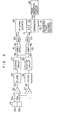
- FIG. 1 shows schematically a general arrangement of a track searching system of an optical information recording and/or reproducing apparatus for recording and/or reproducing information or data implemented according to an embodiment of the present invention.
- a laser beam 2 emitted from a laser light source 1 is varied in a direction (i.e. deflected) by a tracking mirror 3 and converged onto a disc-like information carrier 5 through a focusing lens 4 in a form of a fine (i.e. extremely small) light spot 6 of about 1 ⁇ m in diameter.
- a driving unit 7 which may be composed of a voice coil or the like and serves for causing the focusing lens 4 to be finely moved vertically (as viewed in Fig, 1) in accordance with vibrations or fluctuations of the disc-like information carrier 5 relative to a fixed horizontal reference plane (as viewed in Fig. 1), so that the fine light spot 6 is projected onto the information carrier 5 in the properly focused state regardless of fluctuations thereof.
- the information carrier or disc 5 provided previously with guide tracks 8 is adapted to be rotated at a high speed by means of an electric motor 9 and additionally adapted to be displaced in the radial direction of the carrier 5 at a high speed by means of a track locating or searching scanning mechanism 10 which may be constituted by a pulse motor and a lead screw or the like combination.
- a track locating or searching scanning mechanism 10 which may be constituted by a pulse motor and a lead screw or the like combination.
- the information carrier 5 and the rotating motor 9 are linearly displaced by the track locating scanning mechanism 10 in the case of the exemplary embodiment shown in Fig. 1, it is equally possible to displace in the radial direction the whole optical system inclusive of the focusing lens 4 for searching the desired track, while the information carrier 5 and the motor 9 are stationarily positioned.
- a reflected laser beam 11 reflected from the information carrier 5 is, after having passed through the lens 4 and undergone reflection by the mirror 3, transmitted through a quarterwave (1/4 - ⁇ ) plate 12 and split by a polarized light beam splitter 13.
- the beam 15 split by the beam splitter 13 is transmitted through a lens 16 to impinge on a vertex of a biprism 14, whereby the split beam 15 is divided into halved beams 17a and 17b.
- the halved beam 17a impinges on a photoelectric detector l8 for detecting the focusing state, while the halved beam 17b is received by another photoelectric detector 19 for detecting the tracking state,.as will hereinafter be described in detail,
- the beam 17a is moved to the right and left (as viewed in Fig. 1) on the light receiving surface of the photoelectric detector 18 in accordance with vertical fluctuations of the surface of the disc-like information carrier 5.
- the photoelectric detector 18 has a right-hand photoelectric cell and a left-hand photoelectric cell. The outputs of these cells are coupled to two inputs of a differential amplifier 20, ⁇ respectively.
- the output signal 21 from the differential amplifier 20 represents an error in the focused state of the scanning beam 2.
- the focus error signal 21 is applied to the focusing lens driving circuit 70 to thereby move the focusing or converging lens 4 in the vertical direction so that the scanning beam 2 is properly focused on the information carrier 5.
- the fine light spot 6 is displaced transversely of the guide track 8 formed in the disc-like information carrier 5 due to possible eccentricity of the latter.
- distribution of light quantity of the halved beam 1.7b produced from the biprism 14 and projected on to the photoelectric tracking detector 19 undergoes variation (i.e. becomes non-uniform) along the vertical axis of the detector 19 (as viewed in Fig. 1).
- the photoelectric detector 19 is composed of an upper cell and a lower cell (as viewed in Fig.
- a difference signal 23 outputted from the differential amplifier 22 represents an error in the tracking of the fine light spot 6 along the track 8 due to eccentricity thereof or of the information carrier 5.
- the tracking error signal 23 thus derived is then applied to a tracking mirror driving circuit 24 to correspondingly vary angle of inclination of the tracking mirror 3 so that the focused fine light spot 6 may follow accurately the guide track 8 formed in the disc-like information carrier 5.
- a reference numeral 25 denotes a signal processing circuit which will hereinafter be described in detail referring to Fig. 5.
- This signal processing circuit 25 is adapted to prepare a track traverse pulse and a track traversing direction signal both of which are applied to a track searching or locating driving circuit 26 which in turn serves to control the track searching or locating mechanism so that the fine light spot 6 is moved to a desired track position.
- Reference numeral 27 denotes a summing amplifier which serves to produce a sum signal 28 on the basis of the two output signals from the photoelectric tracking detector 19 described above, The sum signal 28 is also applied to the input of the signal processing circuit 25.
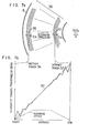
- Fig. 2 which shows in a fragmental sectional view a structure of the disc-like information carrier 5 designed to be used in the optical information recording/reproducing apparatus according to the invention
- channel-or groove-like guide tracks 30a to 30e in Fig. 1, shown at 8
- the width and depth of the track are represented by ⁇ and 6, respectively.
- Numerals 29a to 29e denote flat portions or platforms extending between the adjacent guide tracks.
- a light-sensitive recording material is deposited on the whole surface R of a substrate 32 through evaporation and constitutes a recording layer 31.
- the laser beam 2 may be converged on the surface R in the form of the fine or minute light spot 6 by irradiating the laser beam 2 from the rear side of the substrate 32 to record information on the light-sensitive layer 31.
- a state of record in the channel-like track is illustrated at 103 in Fig. 2.
- those areas shown as blackened areas of the recording material since the light does not transmit therethrough and exhibiting an increased reflection factor represent recorded information.
- the recording of information is made on the bottom of the guide tracks 30a to 30e.
- width w 0.6 ⁇ m
- P 1.6 ⁇ m and ⁇ ⁇ ⁇ /8n
- ⁇ represents the wavelength of the laser light
- n refractive index of the substrate 32.
- FIGs. 3a to 3d illustrate in more detail the principle of detecting the tracking error which is possibly brought about when the groove- or channel-like track 30 of the information carrier 5 is irradiated with the fine light spot 6.
- These figures 3a to 3d show a -section of a track taken along the radial direction of the information carrier 5.
- the photoelectric tracking detector 19 is constituted by a pair of photoelectric cells 19a and 19b which are disposed functionally, in juxtaposition across the longitudinal center axis of the track 30. Moreparticularly, it is assumed that the photoelectric cell 19a is associated with the radially outer half of the track 30 with reference to the longitudinal center axis thereof, while the photoelectric cell 19b is associated with the radially inner half of the track 30.
- the reflected laser rays lla and llb from the information carrier 5 are projected onto the photoelectric tracking detector 19 in a form of the light spot 17b (i.e. the halved beam 17b shown in Fig. 1) in which blackened and hatched areas represent difference in the distribution of incident light quantity.
- the fine light spot 6 of the scanning laser beam 2 is located on the flat portion 29 extending between the adjacent guide tracks formed in the information carrier 5,
- the incident light spot 6 undergoes uniform reflection as indicated by lla and impinges onto the photoelectric tracking detector 19 in the uniform distribution of light quantity, resulting in that the output signal from the differential amplifier 22 is equal to zero.
- the tracking error signal 23 is also zero.
- the incident fine light spot 6 covers partially the radially outer edge portion 33a of the channel-like guide track 30.
- the depth 6 of the track 30 corresponds to about ⁇ /4 in terms of phase of the laser beam
- the laser ray reflected from the track 30a at the radially outer edge portion thereof is diffracted radially outwardly, resulting in that the photoelectric cell 19a is irradiated more intensively, while the photoelectric cell 19b is irradiated less intensively.
- the output signal 23 from the differential amplifier 22 becomes positive when the output signals from the photoelectric cells 19a and 19b are applied, respectively, to the positive and the negative inputs of the differential amplifier 22.
- the incident fine light spot 6 is properly centered on the channel-like guide track 30.
- the fine light spot-6 covers both edge portions 33a and 33b of the channel-like track, the laser rays reflected at these portions are diffracted outwardly from the aperture of. the focusing lens 4 and a portion of the light quantity is lost.
- the distribution of light quantity is uniform over both the photoelectric cells 19a and 19b, the total quantity of incident light on the photoelectric cells 19a and 19b is reduced as compared with the cases illustrated in Figs. 3a, 3b and 3d.
- the difference signal 23 produced from the differential amplifier 22 is zero as in the case of the tracking condition illustrated in Fig. 3a.
- the sum signal 28 produced from the summing amplifier 27 and representing the sum of the output signals from the photoelectric cells 19a and 19b has a smaller amplitude than that of the sum signals derived in the irradiation states illustrated in Figs. 3a. 3b and 3d.
- Fig. 3d illustrates the state in which the fine light spot 6 covers partially a radially inner edge portion 33b of the track 30 in contrast to the case described above in conjunction with Fig. 3b.
- the laser rays lid reflected at the radially inner track edge portion are diffracted radially inwardly, resulting in that the quantity of light impinging onto the photoelectric cell 19b is correspondingly increased.
- the difference signal 23 produced by the differential amplifier 22 takes a negative value.
- Figs. 4a and 4b show signal waveforms of the sum signal 28 and the difference signal 23 of the output signals 34a and 34b which are produced, respectively, from the photoelectric cells 19a and 19b of the photoelectric tracking detector 19 when the fine light spot 6 traverses the single guide track upon radial displacement of the scanning laser beam.
- the signal waveforms shown in Figs. 4a are depicted on the assumption that the scanning is effected radially inwardly, while the signal waveforms shown in Fig. 4b are plotted for the case in which the scanning.is effected radially outwardly.
- the peak of the sum signal 28 coincides with the zero-crossing point of the difference signal 23, which is independent from the scanning direction, as is obvious from the above elucidation made by referring to Figs. 3a to 3d.
- the waveforms of the sum signal 28 and the difference signal 23 are compared with each other in respect to the phase, it can be seen that when the scanning beam traverses the channel-like guide track 30 in the radially inward direction, the sum signal 28 is advanced in phase relative to the negative polarity component of the difference signal 23, as is shown in Fig. 4a.
- the scanning laser beam 2 traverses the channel-like track in the radially outward direction
- the sum signal 28 is delayed relative to the negative polarity component of the difference signal 23, as is shown in Fig. 4b.
- the detection of the traversing direction of the scanning laser beam can be accomplished in a very stable manner with a high reliability.
- Fig. 5 shows in a block diagram the signal processing circuit denoted generally by. the reference numeral 25 in Fig. 1. This circuit serves to locate a given track by counting the number of the tracks which have been traversed by the scanning laser beam.
- Fig. 6 shows waveforms of signals produced by circuit blocks shown in Fig. 5.
- the output signals 34a and 34b from the photoelectric cells 19a and 19b which constitute the photoelectric tracking detector 19 are supplied to the differential amplifier 22 and at the same time to the summing amplifier 27 to thereby derive the difference signal 23 and the sum signal 28, respectively.
- These signals 23 and 28 are fed to filters 35 and 36, respectively, to eliminate unwanted signal components such as instrumental noise and the like and subsequently supplied to shaping circuits 37 and 38, respectively, to be shaped into rectangular waveforms 39 and 40 (refer to Fig. 6).
- the shaped difference signal 39 and the shaped sum signal 40 contain no components of negative polarity which have been sliced away with reference to a predetermined threshold level.
- the shaped difference signal 39 is applied to the input of a mono-stable multivibrator 41 which is then triggered by the rising edge of the difference signal pulse 39 to thereby produce a needle pulse difference signal 42.
- This pulse signal 42 is applied to an AND gate 43 together with the shaped sum signal 40.
- the logical product output from the AND gate 43 is a pulse signal 44 (refer to Fig. 6) which represents the radially inward traversing'of the scanning laser beam and will hereinafter be referred to as the radially inward traverse pulse signal 44.
- a mono-stable multivibrator 45 is triggered by the rising edge of the shaped sum signal pulse 40 to produce a needle pulse sum signal 46 (Fig. 6), which is then applied to a second AND gate 47 together with the shaped difference signal 39.
- the logical product output from the AND gate 47 is then a pulse signal 48 which represents the radially outward traversing of the scanning laser beam and which will hereinafter be referred to as the radially outward traverse pulse signal 48.
- the total number of the radially inward traverse pulses 44 and the total number of the radially outward traverse pulses 48 represent, respectively, the number of tracks traversed by the scanning laser beam in the radially inward direction of the information carrier and the number of tracks traversed in the radially outward direction, even when a same track is traversed several times by the laser beam with the traversing direction being reversed from the radially inward to the radially outward direction and vice versa, as will be described hereinafter.
- the radially inward traverse pulse signal 44 is fed to an up-count input of an up-down counter 49, while the radially outward traverse pulse signal 48 is fed to a down-count input of the up-down counter 49.
- the output count pulse signal appearing at the output 50 of the counter 49 represents the net number of tracks which have been traversed by the laser beam in the radially inward direction.
- the output count signal 50 from the up-down counter 49 is supplied to one input of a comparator 53 which has the other input supplied with a desired track traversal number signal 52 representating a desired number of tracks to be traversed and placed in a track traversal number setting register 51.
- the comparator 53 produces at the output thereof a track searching stop signal 54 which is supplied to the track searching drive circuit 26 to stop the track searching or locating operation.
- Figs. 7a and 7b illustrate counting of the traversed tracks and influences ascribable to track eccentricity in the operation for searching or locating a given desired track.
- the track searching mechanism 10 is braked, whereby the searching speed is decreased so that the fine light spot stops at the desired track 57.
- a profile of such track searching speed is represented by a broken line curve in Fig. 7b.
- the track searching speed is low relative to the rotating speed of the information carrier 5, resulting in that one and the same track lying in these regions is traversed several times by the light spot due to the eccentricity of the information carrier.
- the difference signal 23 (refer to Fig.
- the desired track 57 can be positively searched by stopping the searching operation when the count output signal 50 produced from the up-down counter 49 coincides with the number of tracks which are to be traversed until the desired or end track has been attained.
- the track searching apparatus allows the number of tracks traversed by the scanning laser beam to be counted accurately regardless of eccentricity of large or small magnitude and thus can assure a high speed track searching operation. Further, by virtue of the phase inversion of the differ- e nce signal in dependence on the track traversing direction, decreasing of the sum signal upon proper focusing of the laser beam on the track and the coincidence between the peak of the sum signal and the phase of the zero-cross point of the difference signal independently from variations in the reflection factor of the information carrier, an improved track searching or locating operation can be accomplished at a high speed.
- Fig. 8 shows in a block diagram a general arrangement of a track searching or indexing apparatus according to another exemplary embodiment of the invention.
- This arrangement allows detection of the track traverse signal with an improved reliability when the recorded tracks are traversed.
- Following description is directed mainly to the arrangement which differs from the one shown in Fig. 1.
- the optical signal picked-up from the disc-like information carrier 5 is detected by the photoelectric detector 19.
- the output signal from the detector 19 is applied to a high-frequency pre-amplifier 101 which produces a reproduced RF signal 102.
- Figs. 9a and 9b illustrate waveforms of a tracking difference signal, a tracking sum signal and a reproduced RF signal produced when an optically recorded track such as the one denoted by 103 in Fig. 2 is traversed by the light spot of the laser beam. It should be recalled that description made hereinbefore in conjunction with Figs. 4a and 4b applies tothe track searching operation in which no information has been optically recorded in the light-sensitive layer of the information carrier disc along the channel-like tracks.
- the exposed portion When the light-sensitive material of the channel-like guide track is exposed to a recording irradiation, the exposed portion exhibits an increased reflection factor. As a consequence, not only the amplitude of the output signals from the photoelectric detectors is increased correspondingly, but also amplitude of the difference signals 23a and 23b is increased. On the other hand, amplitude of the sum signals 104a, 104b derived at the center of the channel (groove) are not decreased (or the level is not lowered) so remarkably as the sum signal 28 described hereinbefore in conjunction with Figs. 4a and 4b, as is indicated by 104a and 104b in Figs.
- the reproduced RF signal should preferably be employed in place of the sum signal (104a; 104b) in the case of the recorded track. Waveforms of the reproduced RF signal are indicated by solid line curves 105a and 105b in Figs. 9a and 9b.
- Fig. 9a illustrates the signal waveforms in concern on the assumption that the light spot traverses the recorded tracks in the radially inward direction as in the case of Fig. 4a, while the signal waveforms shown in Fig. 9b is depicted for the track scanning in the radially outward direction, as in the case of Fig. 4 b .
- the track traversing direction of the scanning laser beam can be easily determined by detecting the difference in phase between the sum signal and the difference signal for the unrecorded track portion on one hand and the difference in phase between the reproduced signal and the difference signal for the recorded track portion on the other hand.
- determination of the track traversing direction as well as the counting of the number of tracks traversed by the scanning laser beam can be accomplished regardless of whether information is recoreded or not on the tracks.
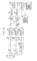
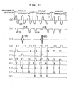
- Fig. 10 shows in a block diagram a circuit configuration of the signal processing circuit denoted by a reference numeral 25 in Fig. 8, and Fig. 11 shows waveforms a to k of signals produced at various points a to k of the circuit 25 on a same time scale.
- a reference numeral 101 denotes the high-frequency pre-amplifier for amplifyingthe reproduced or picked-up signal.
- the difference signal a is applied to a low-pass filter 35 for passing only the detection signal representative of the traversal of channel-like guide track by eliminating other instrumental or the like noise components.
- the output signal from the low-pass filter 35 is fed to a shaping circuit 37 through which only the negative component of the difference signal 23 is outputted as a shaped pulse signal (refer to waveform d in Fig. 11).
- the sum signal b is also fed to a low-pass filter 36 and then to a shaping circuit 38 to be shaped into a pulse signal d shown in Fig. 11.
- the reproduced signal c is supplied to a detection circuit 106 to undergo an envelope detection.
- the output signal from the detector 106 is passed through a low-pass filter 107 and supplied to a shaping circuit 108 to be shaped into a pulse signal of waveform f shown in Fig. 11.
- the sum signal pulse e and the reproduced signal pulse f are applied to the inputs of an OR circuit 109.
- the logical sum pulse output (refer to Fig. 11 at g) from the OR circuit 109 represents the longitudinal center of the channel-like track regardless of presence or absence of recorded information.
- the difference signal pulse d and the logical sum pulse g are applied to mono-stable multivibrators 41 and 45, respectively, which are triggered by the rising edges of the respective input pulses to thereby produce output pulses each of a short pulse width.
- the output pulse h from the mono-stable multivibrator 41 triggered by the rising edge of the difference signal pulse is subjected to phase comparison with the logical sum pulse g through an AND circuit 43.
- the output pulse i from the mono-stable multivibrator 45 triggered by the rising edge of the logical sum pulse g undergoes phase comparison with the difference signal pulse d.
- the radially outward traverse pulse shown in Fig. 11 at k is produced.
- the radially inward traverse pulses j are applied to an up-count clock terminal of an up-down counter 49, while the radially outward traverse pulses k are applied to a down-count clock terminal of the up-down counter 49. Then, there makes appearance at the count output of the up-down counter 49 a signal representative of the net number of the tracks traversed by the light spot in the radially inward direction. For the same reason as mentioned hereinbefore in conjunction with the first exemplary embodiment of the invention, it is possible to determine the number of the traversed tracks with high accuracy even when the light spot is caused to traverse by repeated inversion of traversing direction a same track due to eccentricity of the disc-like information carrier.
Landscapes
- Moving Of The Head For Recording And Reproducing By Optical Means (AREA)
Applications Claiming Priority (4)
| Application Number | Priority Date | Filing Date | Title |
|---|---|---|---|
| JP130942/80 | 1980-09-19 | ||
| JP55130942A JPS5755542A (en) | 1980-09-19 | 1980-09-19 | Track retrieving device of optical information recorder and reproducer |
| JP138165/80 | 1980-10-01 | ||
| JP55138165A JPS5764337A (en) | 1980-10-01 | 1980-10-01 | Track retrieval device |
Publications (3)
| Publication Number | Publication Date |
|---|---|
| EP0048441A2 true EP0048441A2 (fr) | 1982-03-31 |
| EP0048441A3 EP0048441A3 (en) | 1982-08-04 |
| EP0048441B1 EP0048441B1 (fr) | 1986-09-03 |
Family
ID=26465926
Family Applications (1)
| Application Number | Title | Priority Date | Filing Date |
|---|---|---|---|
| EP81107323A Expired EP0048441B1 (fr) | 1980-09-19 | 1981-09-16 | Dispositif de localisation de piste pour un appareil d'enregistrement et de reproduction optique d'information |
Country Status (3)
| Country | Link |
|---|---|
| US (1) | US4484319A (fr) |
| EP (1) | EP0048441B1 (fr) |
| DE (1) | DE3175265D1 (fr) |
Cited By (15)
| Publication number | Priority date | Publication date | Assignee | Title |
|---|---|---|---|---|
| US4443869A (en) * | 1981-09-28 | 1984-04-17 | Rca Corporation | Track jump servo system for disc player |
| EP0125019A1 (fr) * | 1983-04-05 | 1984-11-14 | Pioneer Electronic Corporation | Dispositif pour commander des opérations de saut de piste d'enregistrement |
| FR2558001A1 (fr) * | 1984-01-10 | 1985-07-12 | Canon Kk | Procede et appareil pour la recherche d'une piste sur un support optique d'information. |
| EP0141396A3 (en) * | 1981-11-25 | 1985-10-02 | Hitachi, Ltd. | Access device for positioning a light beam to a desired guide groove of an optical memory apparatus |
| EP0192433A1 (fr) * | 1985-02-16 | 1986-08-27 | Brother Kogyo Kabushiki Kaisha | Tête optique pour l'enregistrement et la reproduction de données optiques |
| FR2590064A1 (fr) * | 1985-11-08 | 1987-05-15 | Seiko Epson Corp | Dispositif de lecture/ecriture optique |
| EP0154302A3 (en) * | 1984-02-29 | 1988-01-07 | Kabushiki Kaisha Toshiba | Optical system for detecting a position of an objective lens |
| US4755036A (en) * | 1985-02-07 | 1988-07-05 | Brother Kogyo Kabushiki Kaisha | Apparatus for deflecting light beam |
| US4765703A (en) * | 1985-08-05 | 1988-08-23 | Brother Kogyo Kabushiki Kaisha | Optical deflector |
| US4792201A (en) * | 1986-04-09 | 1988-12-20 | Brother Kogyo Kabushiki Kaisha | Optical deflector device |
| WO1989002150A1 (fr) * | 1987-08-29 | 1989-03-09 | Fujitsu Limited | Procedes d'acces a une piste d'enregistrement optique |
| US4816912A (en) * | 1985-06-08 | 1989-03-28 | Brother Kogyo Kabushiki Kaisha | Laser-beam printer with improved optical deflector |
| US4841311A (en) * | 1986-09-20 | 1989-06-20 | Brother Kogyo Kabushiki Kaisha | Laser beam printer with compactly arranged photosensitive element, laser beam emitting element and reflective element |
| WO1990005361A1 (fr) * | 1987-03-02 | 1990-05-17 | Unisys Corporation | Systeme de servocommande pour unite de disques |
| US4983499A (en) * | 1986-09-11 | 1991-01-08 | Brother Kogyo Kabushiki Kaisha | Method of forming waveguide lens having refractive index distribution |
Families Citing this family (22)
| Publication number | Priority date | Publication date | Assignee | Title |
|---|---|---|---|---|
| JPS58200473A (ja) * | 1982-05-19 | 1983-11-22 | Pioneer Video Kk | 情報読取装置 |
| JPS5919250A (ja) * | 1982-07-21 | 1984-01-31 | Hitachi Ltd | 情報の記録再生装置 |
| JPS6010429A (ja) * | 1983-06-30 | 1985-01-19 | Toshiba Corp | 光デイスク装置 |
| JPS60171638A (ja) * | 1984-02-16 | 1985-09-05 | Matsushita Electric Ind Co Ltd | 情報再生装置 |
| JPS60258738A (ja) * | 1984-05-18 | 1985-12-20 | Olympus Optical Co Ltd | トラック検索方法 |
| JPS6139239A (ja) * | 1984-07-28 | 1986-02-25 | Sony Corp | 光学式デイスクプレ−ヤ |
| US5173886A (en) * | 1986-02-07 | 1992-12-22 | Matsushita Electric Industrial Co., Ltd. | Composite optical disc having both a data read-only area and a data rewritable area, and a recording/reproducing system for use therewith |
| EP0542730B1 (fr) | 1986-02-07 | 1997-07-30 | Matsushita Electric Industrial Co., Ltd. | Disque optique et appareil à disques pour enregistrer ou reproduire des données sur le ou à partir du disque |
| US5124964A (en) * | 1986-08-12 | 1992-06-23 | Kabushiki Kaisha Toshiba | Focus servo gain setting circuit for optical record disc reproducing apparatus |
| JPS63171431A (ja) * | 1987-01-07 | 1988-07-15 | Mitsubishi Electric Corp | 光デイスク駆動装置 |
| ATE98803T1 (de) * | 1987-02-27 | 1994-01-15 | Sony Corp | Plattenaufzeichnungsgeraet. |
| DE3732899A1 (de) * | 1987-09-30 | 1989-04-20 | Thomson Brandt Gmbh | Spurregelkreis fuer eine optische abtastvorrichtung |
| US4858041A (en) * | 1987-10-20 | 1989-08-15 | Mattel, Inc. | Tracking servo control |
| DE3932833A1 (de) * | 1989-09-30 | 1991-04-11 | Thomson Brandt Gmbh | Zaehlvorrichtung |
| JP2723636B2 (ja) * | 1989-11-20 | 1998-03-09 | 株式会社日立製作所 | トラッキング制御装置 |
| US5199017A (en) * | 1991-09-11 | 1993-03-30 | International Business Machines Corporation | Optical disk drive and method for counting the number of tracks on an optical disk |
| USRE36864E (en) * | 1990-09-27 | 2000-09-12 | International Business Machines Corporation | Optical disk drive and methods for counting the number of tracks on an optical disk |
| JP3100478B2 (ja) * | 1992-10-27 | 2000-10-16 | 株式会社トプコン | 往復レーザ走査システムを有するレーザ回転照射装置 |
| JPH08263850A (ja) * | 1995-03-22 | 1996-10-11 | Olympus Optical Co Ltd | 光学式記録再生装置 |
| US5719836A (en) | 1995-04-07 | 1998-02-17 | Discovision Associates | Optical seeking method and apparatus generating track count signal from tracking error signal and data signal |
| DE10062079A1 (de) * | 2000-12-13 | 2002-06-27 | Thomson Brandt Gmbh | Verfahren zum Spurzählen und entsprechendes Gerät zum Lesen und/oder Beschreiben eines optischen Aufzeichnungsträgers |
| EP2028450A2 (fr) * | 2007-07-27 | 2009-02-25 | Melexis NV | Capteur de position |
Family Cites Families (15)
| Publication number | Priority date | Publication date | Assignee | Title |
|---|---|---|---|---|
| US3932700A (en) * | 1974-02-04 | 1976-01-13 | Zenith Radio Corporation | Focus tracking registration for optical reproducing systems |
| NL7412634A (nl) * | 1974-09-25 | 1976-03-29 | Philips Nv | Registratiedrager voor een televisiesignaal. |
| NL7413162A (nl) * | 1974-10-07 | 1976-04-09 | Philips Nv | Inrichting voor het uitlezen van een schijf- vormige registratiedrager. |
| NL177157C (nl) * | 1975-02-28 | 1985-08-01 | Philips Nv | Inrichting voor het uitlezen van een vlakke registratiedrager met een optisch uitleesbare informatiestruktuur. |
| NL7510035A (nl) * | 1975-08-26 | 1977-03-01 | Philips Nv | Registratiedrager met een optisch uitleesbare, langs sporen gerangschikte, informatiestruktuur en inrichting voor het uitlezen daarvan. |
| NL7600843A (nl) * | 1976-01-28 | 1977-08-01 | Philips Nv | Inrichting voor het uitlezen van een registratie- drager waarop informatie, bijvoorbeeld en/of ge- luidsinformatie, is aangebracht. |
| JPS52119904A (en) * | 1976-04-01 | 1977-10-07 | Nippon Gakki Seizo Kk | Arm control device |
| FR2349191A1 (fr) * | 1976-04-23 | 1977-11-18 | Thomson Brandt | Lecteur optique de disque d'information comportant un dispositif d'acces automatique aux informations |
| JPS5398802A (en) * | 1977-02-09 | 1978-08-29 | Mitsubishi Electric Corp | Optical reproducer |
| FR2396379A1 (fr) * | 1977-07-01 | 1979-01-26 | Thomson Brandt | Lecteur optique de disque d'information muni d'un dispositif d'acces automatique aux informations |
| NL187413C (nl) * | 1978-03-16 | 1991-09-16 | Philips Nv | Registratiedragerlichaam, ingeschreven registratiedrager, werkwijze voor het inschrijven van het registratiedragerlichaam en inrichting voor het uitvoeren van de werkwijze en voor het uitlezen van een ingeschreven registratiedrager. |
| EP0007199B1 (fr) * | 1978-06-30 | 1986-12-30 | Discovision Associates | Procédé et dispositif d'exploration d'un porteur d'enregistrement lisible par voie optique |
| JPS6040093B2 (ja) * | 1978-09-09 | 1985-09-09 | パイオニアビデオ株式会社 | トラッキングサ−ボ引込装置 |
| JPS5567946A (en) * | 1978-11-17 | 1980-05-22 | Hitachi Ltd | Automatic position tracer |
| NL8000122A (nl) * | 1980-01-09 | 1981-08-03 | Philips Nv | Schijfvormige, optisch uitleesbare registratiedrager als opslagmedium voor datainformatie, inrichting voor het vervaardigen van zo'n registratiedrager, inrichting voor het optekenen en/of weergeven van datainformatie in c.q. van zo'n registratiedrager. |
-
1981
- 1981-09-11 US US06/301,420 patent/US4484319A/en not_active Expired - Lifetime
- 1981-09-16 EP EP81107323A patent/EP0048441B1/fr not_active Expired
- 1981-09-16 DE DE8181107323T patent/DE3175265D1/de not_active Expired
Cited By (18)
| Publication number | Priority date | Publication date | Assignee | Title |
|---|---|---|---|---|
| US4443869A (en) * | 1981-09-28 | 1984-04-17 | Rca Corporation | Track jump servo system for disc player |
| EP0141396A3 (en) * | 1981-11-25 | 1985-10-02 | Hitachi, Ltd. | Access device for positioning a light beam to a desired guide groove of an optical memory apparatus |
| EP0125019A1 (fr) * | 1983-04-05 | 1984-11-14 | Pioneer Electronic Corporation | Dispositif pour commander des opérations de saut de piste d'enregistrement |
| FR2558001A1 (fr) * | 1984-01-10 | 1985-07-12 | Canon Kk | Procede et appareil pour la recherche d'une piste sur un support optique d'information. |
| EP0154302A3 (en) * | 1984-02-29 | 1988-01-07 | Kabushiki Kaisha Toshiba | Optical system for detecting a position of an objective lens |
| US4755036A (en) * | 1985-02-07 | 1988-07-05 | Brother Kogyo Kabushiki Kaisha | Apparatus for deflecting light beam |
| EP0192433A1 (fr) * | 1985-02-16 | 1986-08-27 | Brother Kogyo Kabushiki Kaisha | Tête optique pour l'enregistrement et la reproduction de données optiques |
| US4855986A (en) * | 1985-02-16 | 1989-08-08 | Brother Kogyo Kabushiki Kaisha | Data storage and readout optical head using a single substrate having an electrooptic converging portion for adjustment of the light beam focal point |
| US4816912A (en) * | 1985-06-08 | 1989-03-28 | Brother Kogyo Kabushiki Kaisha | Laser-beam printer with improved optical deflector |
| US4765703A (en) * | 1985-08-05 | 1988-08-23 | Brother Kogyo Kabushiki Kaisha | Optical deflector |
| FR2590064A1 (fr) * | 1985-11-08 | 1987-05-15 | Seiko Epson Corp | Dispositif de lecture/ecriture optique |
| US4792201A (en) * | 1986-04-09 | 1988-12-20 | Brother Kogyo Kabushiki Kaisha | Optical deflector device |
| US4983499A (en) * | 1986-09-11 | 1991-01-08 | Brother Kogyo Kabushiki Kaisha | Method of forming waveguide lens having refractive index distribution |
| US4841311A (en) * | 1986-09-20 | 1989-06-20 | Brother Kogyo Kabushiki Kaisha | Laser beam printer with compactly arranged photosensitive element, laser beam emitting element and reflective element |
| WO1990005361A1 (fr) * | 1987-03-02 | 1990-05-17 | Unisys Corporation | Systeme de servocommande pour unite de disques |
| WO1989002150A1 (fr) * | 1987-08-29 | 1989-03-09 | Fujitsu Limited | Procedes d'acces a une piste d'enregistrement optique |
| US5121370A (en) * | 1987-08-29 | 1992-06-09 | Fujitsu Limited | Apparatus and method for accurately scanning a light beam across tracks of a recording medium |
| USRE36590E (en) * | 1987-08-29 | 2000-02-29 | Fujitsu Limited | Apparatus and method for accurately scanning a light beam across tracks of a recording medium |
Also Published As
| Publication number | Publication date |
|---|---|
| EP0048441B1 (fr) | 1986-09-03 |
| DE3175265D1 (en) | 1986-10-09 |
| US4484319A (en) | 1984-11-20 |
| EP0048441A3 (en) | 1982-08-04 |
Similar Documents
| Publication | Publication Date | Title |
|---|---|---|
| US4484319A (en) | Apparatus for locating a track on disc-like optical information carriers | |
| EP0050967B1 (fr) | Système de détection d'informations pour appareil de lecture optique | |
| US4293944A (en) | Information play-back apparatus with astigmatic auto-focusing | |
| KR100324848B1 (ko) | 광재생장치 | |
| US4422168A (en) | Method and apparatus for detecting a focussing condition of an objective lens | |
| US5268883A (en) | Track access device and tracking control device | |
| US4648085A (en) | Optical information recording and reading apparatus with error correction | |
| KR950008669B1 (ko) | 광기록 매체 구동 장치 | |
| US5311490A (en) | Access controlling device for use in an optical disk drive | |
| US4525825A (en) | Method and apparatus for detecting focussing and tracking error signals | |
| US5283778A (en) | Pickup device | |
| JPH10124900A (ja) | トラッキング制御装置及びトラック検索装置 | |
| US4445208A (en) | Signal detecting system in optical information reading apparatus | |
| JPS6260731B2 (fr) | ||
| US4499572A (en) | Method for reading information or defect out of rotating disc | |
| JPH0799592B2 (ja) | 光学式情報記憶担体 | |
| JP2854131B2 (ja) | 光ビームがデータトラックから離れたことを検知するための方法および光ビームがデータトラックから離れたことを検知するための検知回路 | |
| CN1053056C (zh) | 光拾取装置 | |
| JPS6236286B2 (fr) | ||
| JPS6360449B2 (fr) | ||
| JP2887273B2 (ja) | 光学式ピックアップ装置 | |
| KR0124618B1 (ko) | 광자기 디스크의 기록밀도 판별방법 | |
| JPH0150972B2 (fr) | ||
| DE520461T1 (de) | Geraet zum aufzeichnen und wiedergeben von optischen platten. | |
| KR100662265B1 (ko) | 광 기록매체의 비기록 영역 검출 방법 및 이를 이용한 기록재생 방법 및 그 장치 |
Legal Events
| Date | Code | Title | Description |
|---|---|---|---|
| PUAI | Public reference made under article 153(3) epc to a published international application that has entered the european phase |
Free format text: ORIGINAL CODE: 0009012 |
|
| AK | Designated contracting states |
Designated state(s): DE FR GB |
|
| PUAL | Search report despatched |
Free format text: ORIGINAL CODE: 0009013 |
|
| AK | Designated contracting states |
Designated state(s): DE FR GB |
|
| 17P | Request for examination filed |
Effective date: 19830112 |
|
| GRAA | (expected) grant |
Free format text: ORIGINAL CODE: 0009210 |
|
| AK | Designated contracting states |
Kind code of ref document: B1 Designated state(s): DE FR GB |
|
| REF | Corresponds to: |
Ref document number: 3175265 Country of ref document: DE Date of ref document: 19861009 |
|
| ET | Fr: translation filed | ||
| PLBE | No opposition filed within time limit |
Free format text: ORIGINAL CODE: 0009261 |
|
| STAA | Information on the status of an ep patent application or granted ep patent |
Free format text: STATUS: NO OPPOSITION FILED WITHIN TIME LIMIT |
|
| 26N | No opposition filed | ||
| PGFP | Annual fee paid to national office [announced via postgrant information from national office to epo] |
Ref country code: DE Payment date: 20000911 Year of fee payment: 20 |
|
| PGFP | Annual fee paid to national office [announced via postgrant information from national office to epo] |
Ref country code: FR Payment date: 20000912 Year of fee payment: 20 |
|
| PGFP | Annual fee paid to national office [announced via postgrant information from national office to epo] |
Ref country code: GB Payment date: 20000913 Year of fee payment: 20 |
|
| PG25 | Lapsed in a contracting state [announced via postgrant information from national office to epo] |
Ref country code: GB Free format text: LAPSE BECAUSE OF EXPIRATION OF PROTECTION Effective date: 20010915 |
|
| REG | Reference to a national code |
Ref country code: GB Ref legal event code: PE20 Effective date: 20010915 |