EP0048457A2 - Dispositif de changement d'outil pour machines-outils - Google Patents
Dispositif de changement d'outil pour machines-outils Download PDFInfo
- Publication number
- EP0048457A2 EP0048457A2 EP81107375A EP81107375A EP0048457A2 EP 0048457 A2 EP0048457 A2 EP 0048457A2 EP 81107375 A EP81107375 A EP 81107375A EP 81107375 A EP81107375 A EP 81107375A EP 0048457 A2 EP0048457 A2 EP 0048457A2
- Authority
- EP
- European Patent Office
- Prior art keywords
- magazine
- tool
- spindle
- drum
- changing
- Prior art date
- Legal status (The legal status is an assumption and is not a legal conclusion. Google has not performed a legal analysis and makes no representation as to the accuracy of the status listed.)
- Withdrawn
Links
Images


Classifications
-
- B—PERFORMING OPERATIONS; TRANSPORTING
- B23—MACHINE TOOLS; METAL-WORKING NOT OTHERWISE PROVIDED FOR
- B23Q—DETAILS, COMPONENTS, OR ACCESSORIES FOR MACHINE TOOLS, e.g. ARRANGEMENTS FOR COPYING OR CONTROLLING; MACHINE TOOLS IN GENERAL CHARACTERISED BY THE CONSTRUCTION OF PARTICULAR DETAILS OR COMPONENTS; COMBINATIONS OR ASSOCIATIONS OF METAL-WORKING MACHINES, NOT DIRECTED TO A PARTICULAR RESULT
- B23Q3/00—Devices holding, supporting, or positioning work or tools, of a kind normally removable from the machine
- B23Q3/155—Arrangements for automatic insertion or removal of tools, e.g. combined with manual handling
- B23Q3/157—Arrangements for automatic insertion or removal of tools, e.g. combined with manual handling of rotary tools
- B23Q3/15706—Arrangements for automatic insertion or removal of tools, e.g. combined with manual handling of rotary tools a single tool being inserted in a spindle directly from a storage device, i.e. without using transfer devices
-
- B—PERFORMING OPERATIONS; TRANSPORTING
- B23—MACHINE TOOLS; METAL-WORKING NOT OTHERWISE PROVIDED FOR
- B23Q—DETAILS, COMPONENTS, OR ACCESSORIES FOR MACHINE TOOLS, e.g. ARRANGEMENTS FOR COPYING OR CONTROLLING; MACHINE TOOLS IN GENERAL CHARACTERISED BY THE CONSTRUCTION OF PARTICULAR DETAILS OR COMPONENTS; COMBINATIONS OR ASSOCIATIONS OF METAL-WORKING MACHINES, NOT DIRECTED TO A PARTICULAR RESULT
- B23Q3/00—Devices holding, supporting, or positioning work or tools, of a kind normally removable from the machine
- B23Q3/155—Arrangements for automatic insertion or removal of tools, e.g. combined with manual handling
- B23Q3/1552—Arrangements for automatic insertion or removal of tools, e.g. combined with manual handling parts of devices for automatically inserting or removing tools
- B23Q3/15526—Storage devices; Drive mechanisms therefor
- B23Q3/15534—Magazines mounted on the spindle
-
- B—PERFORMING OPERATIONS; TRANSPORTING
- B23—MACHINE TOOLS; METAL-WORKING NOT OTHERWISE PROVIDED FOR
- B23Q—DETAILS, COMPONENTS, OR ACCESSORIES FOR MACHINE TOOLS, e.g. ARRANGEMENTS FOR COPYING OR CONTROLLING; MACHINE TOOLS IN GENERAL CHARACTERISED BY THE CONSTRUCTION OF PARTICULAR DETAILS OR COMPONENTS; COMBINATIONS OR ASSOCIATIONS OF METAL-WORKING MACHINES, NOT DIRECTED TO A PARTICULAR RESULT
- B23Q3/00—Devices holding, supporting, or positioning work or tools, of a kind normally removable from the machine
- B23Q3/155—Arrangements for automatic insertion or removal of tools, e.g. combined with manual handling
- B23Q3/1552—Arrangements for automatic insertion or removal of tools, e.g. combined with manual handling parts of devices for automatically inserting or removing tools
- B23Q3/15526—Storage devices; Drive mechanisms therefor
- B23Q2003/15527—Storage devices; Drive mechanisms therefor the storage device including means to latch tools
Definitions
- the invention relates to a tool changing device for a machine tool with a spindle head which can be moved in its axial direction according to the preamble of the main claim.
- Tool changing devices of this type are used for automatic tool changing in the course of scheduled machining operations, preferably in the machining of workpieces by milling, drilling, spark eroding and the like. Like.
- the change times and processes are such. B. controlled by paper tape or magnetic tape. Since the machines do their program unattended, spark erosion machines such. B. also run during the night, very high demands are placed on the changing device with regard to compliance with very tight position tolerances of the tool 3 uge on the spindle and the trouble-free change.
- the object of the invention is to design a tool changing device of the generic type in such a way that only one drive device and simple translational and rotational movements are required for tool changing and transfer.
- the magazine locations of the drum magazine hanging on the spindle housing in its rest position to the side of the spindle head are freely accessible for tool exchange. In its changing position, it hangs to the side of the spindle with a position positioned below it, and the changing movement is carried out with the spindle feed.
- the change of location i.e. the drum magazine is switched on during the support movement during the change of position of the magazine; one or more transfers are possible.
- the particular simplification lies in the use of a magnetic chuck.
- Such magnetic chucks are such. B. known on EDM machines.
- this magnetic chuck is equipped with a permanent magnet for gripping and holding the tool and with a reverse-polarized electromagnet for releasing and replacing the tool, and the circuit of the electromagnet is guided to the bearing of the drum magazine via sliding contacts.
- the chuck is de-energized during the work phases, there is no heating in the chuck and on the tool and whoever which does not require slip rings and contacts as in the case of an electromagnetic chuck of the known type.
- This is particularly advantageous in spark erosion machines with a rotating quill.
- the capacity of modern permanent magnets is sufficient for normal tool weights within the space available on the spindle. A rotary coupling with the tool shank makes no difficulties.
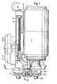
- the quill head 1 of a spark erosion machine is shown as an example, from which the quill 2 with the magnetic chuck 3 emerges at the bottom. 1 is an illustration from the front view of the machine; the base with the machine table is not shown.
- a linear guide 4 for a support 5 and a curved guide 6 for a drum magazine 7 are arranged on the housing or a stand of the side of the quill head 1 (FIGS. 1, 3).
- the straight guide 4 consists of two rods 4.1 (FIG. 3) on which the support 5 is mounted in ball bushings 5.1 and can be displaced vertically.
- the support 5 for this movement is driven by means of a direct current gear motor 8 via a gear 9 and a spindle 10 which is mounted in ball bearings 11 in the frame 4.2 of the straight guide 4.
- the cam guide 6 for the drum magazine 7 consists of two circular 6.1 rails at the lower end, in which the bearing 7.1 of the drum magazine 7 runs with lateral, roller-mounted bearing journals 7.2.
- the bearing 7.1 there is also the bearing pin 7.3 on which the magazine drum 7.4 is rotatably mounted in ball bearings 7.5.
- the bearing journal 7.2 and the bearing pin 7.3 form an axis cross.
- Support 5 and drum magazine 7 are coupled via a bracket 7.6 to the bearing 7.1 in such a way that when the support 5 is pulled up by means of the spindle 10, the magazine 7 is tightened on the bracket 7.6, with its bearing pins 7.2 in the curve guide 6 being guided upwards on an arc is brought from the changing position shown in Fig. 1 next to and below the quill 2 into its (dashed) rest position laterally next to the quill head 1, pivoted by 90 degrees.
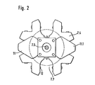
- the magazine drum 7.4 has four fan-shaped magazine places 7.7 that are open to the edge, two of which are occupied by tool holders 11.
- These tool holders have a base plate 11.1 in the form of an equilateral triangle with rounded corners, on which a chuck 11.2 of any type for receiving and clamping a tool or electrode shaft is arranged.
- the tool holders 11 are positioned by the abutment of a surface of their triangular base plate 11.1 on the wall of the drum core, which is square in cross section (FIG. 2), and are held by latching bolts 12 against falling out of the magazine locations 7.7. It can be seen from Fig. 1 that the tool holder 11 can be pulled up in the change position of the magazine drum 7.4, while they are freely accessible from the side in the rest position.
- the pawl 13 can be withdrawn by means of a DC solenoid 15 through the rod 16 from the path of a switching pin 14, so that the. Further switching of the magazine drum 7.4 does not take place.
- repeated upward and downward movement of the support 5 in the area of the pawl 13 can cause the magazine drum 7.4 to be switched several times.
- the sleeve 2 is lowered with the magnetic chuck onto the base plate 11.1 of the tool holder, so that the latter is magnetically clamped.
- the quill then goes up again and / or the drum magazine 7 is raised to its rest position (FIG. 1).
- Fig. 4 shows the construction of the magnetic chuck 3; on its base plate 3.2, which is equipped for clamping onto the quill 2, is a cup-shaped housing 3.1 of the outline and the dimensions of the base plate 11.1 of the tool holder 11.
- a permanent magnet 20 and an electromagnet 21 are accommodated in the housing 3.1.
- the electromagnet 21 is supplied with direct current via contacts 21.1 arranged on the outside of the housing.
- the two magnets 20 and 21 are polarized in opposite directions, their forces are approximately the same, so that the load-bearing capacity of the permanent magnet 20 is canceled when the electromagnet 21 is switched on.
- the circuit of the electromagnet 21 leads via the contacts 21.1 and mating contacts 21.2 on the bearing 7.1 of the drum magazine 7 (Fig.
- the contacts 21.1 / 21.2 are only closed when the sleeve 3 is lowered.
- the circuit remains open when the magnetic chuck 3 has picked up a tool holder 11 from a magazine location 7.7 and pulls it out of its place when the sleeve moves back. However, if a tool holder 11 is inserted into an empty magazine location 7.7, the circuit is closed by the control in order to set it down there, and the magnetic clamping force disappears.
- a tool holder 11 is attached to the magnetic chuck 3 with respect to the quill axis and its angular position centered or adjusted precisely on a reference mark.
- Various systems are known for this, but they are not the subject of the invention and the described function of the device has no influence.
- a tool changing device is extremely simple in its structural design and its functions, namely movements and their control, and is therefore hardly susceptible to repair and is practically maintenance-free.
- the entire changing process is driven by a DC motor 8, a simple switching pawl 13, which is switched ON / OFF by a solenoid 15, is used to advance the drum magazine 7.
- the application of the invention is also not limited to spark erosion machines, only in the case of mechanical machining, a rotational coupling between the tool holder or shank and the magnetic chuck must be provided, which o. W. is possible.
- the design can also be modified in details within the scope of the invention, such as the number of magazine locations and the type of switching mechanism.
Landscapes
- Engineering & Computer Science (AREA)
- Mechanical Engineering (AREA)
- Automatic Tool Replacement In Machine Tools (AREA)
- Electrical Discharge Machining, Electrochemical Machining, And Combined Machining (AREA)
Applications Claiming Priority (2)
| Application Number | Priority Date | Filing Date | Title |
|---|---|---|---|
| DE19803035215 DE3035215A1 (de) | 1980-09-18 | 1980-09-18 | Werkzeugwechseleinrichtung fuer eine werkzeugmaschine |
| DE3035215 | 1980-09-18 |
Publications (2)
| Publication Number | Publication Date |
|---|---|
| EP0048457A2 true EP0048457A2 (fr) | 1982-03-31 |
| EP0048457A3 EP0048457A3 (fr) | 1982-06-23 |
Family
ID=6112274
Family Applications (1)
| Application Number | Title | Priority Date | Filing Date |
|---|---|---|---|
| EP81107375A Withdrawn EP0048457A3 (fr) | 1980-09-18 | 1981-09-17 | Dispositif de changement d'outil pour machines-outils |
Country Status (3)
| Country | Link |
|---|---|
| EP (1) | EP0048457A3 (fr) |
| JP (1) | JPS5783334A (fr) |
| DE (1) | DE3035215A1 (fr) |
Cited By (2)
| Publication number | Priority date | Publication date | Assignee | Title |
|---|---|---|---|---|
| CN108044213A (zh) * | 2018-02-05 | 2018-05-18 | 江苏冬庆数控机床有限公司 | 一种往复走丝电火花线切割机床可交换贮丝筒结构 |
| US20220176505A1 (en) * | 2020-11-18 | 2022-06-09 | Shanghai Jiao Tong University | Electro-hydraulic combined system used for electro machining and supporting automatic tool changing |
Families Citing this family (2)
| Publication number | Priority date | Publication date | Assignee | Title |
|---|---|---|---|---|
| DE3722032C1 (de) * | 1987-07-03 | 1988-09-29 | Erowa Ag | Vorrichtung zur Handhabung von Elektroden an einer Senkerodiermaschine |
| JPH0215937A (ja) * | 1988-07-01 | 1990-01-19 | Matsushita Electric Ind Co Ltd | 工作機 |
Family Cites Families (7)
| Publication number | Priority date | Publication date | Assignee | Title |
|---|---|---|---|---|
| US3526033A (en) * | 1967-09-19 | 1970-09-01 | Pratt & Whitney Inc | Machine tool with tool changer |
| FR2105381A5 (fr) * | 1970-09-03 | 1972-04-28 | Guillemin Sergeot Pegord | |
| DE2264080A1 (de) * | 1972-12-29 | 1974-07-04 | Bw Weber Verwaltungs Gmbh | Werkzeugmaschine mit einer automatischen werkzeugwechselvorrichtung |
| FR2303637A1 (fr) * | 1975-03-13 | 1976-10-08 | Ratier Sa Forest | Perfectionnement aux centres d'usinage a transfert automatique d'outils |
| IT1037252B (it) * | 1975-04-14 | 1979-11-10 | Mandelli Spa | Macchina utensile conportante un unico mandrino atto ad assumere automaticamente siala posizione orizzontale quella verticale ed un unico dispositivo di cambio automatico degli utnesili |
| US4122598A (en) * | 1977-06-03 | 1978-10-31 | Moog Inc. | Tool changer |
| EP0011882B1 (fr) * | 1978-11-29 | 1982-04-07 | Werkzeugmaschinenfabrik Oerlikon-Bührle AG | Machine-outil avec dispositif de changement d'outil |
-
1980
- 1980-09-18 DE DE19803035215 patent/DE3035215A1/de not_active Withdrawn
-
1981
- 1981-09-17 JP JP56147730A patent/JPS5783334A/ja active Pending
- 1981-09-17 EP EP81107375A patent/EP0048457A3/fr not_active Withdrawn
Cited By (4)
| Publication number | Priority date | Publication date | Assignee | Title |
|---|---|---|---|---|
| CN108044213A (zh) * | 2018-02-05 | 2018-05-18 | 江苏冬庆数控机床有限公司 | 一种往复走丝电火花线切割机床可交换贮丝筒结构 |
| CN108044213B (zh) * | 2018-02-05 | 2023-08-18 | 江苏冬庆数控机床有限公司 | 一种往复走丝电火花线切割机床可交换贮丝筒结构 |
| US20220176505A1 (en) * | 2020-11-18 | 2022-06-09 | Shanghai Jiao Tong University | Electro-hydraulic combined system used for electro machining and supporting automatic tool changing |
| US12134158B2 (en) * | 2020-11-18 | 2024-11-05 | Shanghai Jiao Tong University | Electro-hydraulic combined system used for electro machining and supporting automatic tool changing |
Also Published As
| Publication number | Publication date |
|---|---|
| EP0048457A3 (fr) | 1982-06-23 |
| DE3035215A1 (de) | 1982-05-06 |
| JPS5783334A (en) | 1982-05-25 |
Similar Documents
| Publication | Publication Date | Title |
|---|---|---|
| EP0128487B1 (fr) | Machine-outil avec un magasin stationnaire | |
| DE19860492B4 (de) | Programmgesteuerte Fräs- und Bohrmaschine | |
| EP1765550B1 (fr) | Machine-outil | |
| DE2325629C2 (de) | Werkzeugmagazin für eine Werkzeugmaschine | |
| DE3006650C2 (fr) | ||
| DE2739534C2 (de) | Werkzeugwechselvorrichtung | |
| EP0406781A2 (fr) | Magasin pour machine à mesurer les coordonnées | |
| DE68928050T2 (de) | Wickelmaschine für Bipolarständer | |
| CH651237A5 (de) | Werkzeugwechselvorrichtung. | |
| DE102012201728A1 (de) | Palettenwechselvorrichtung für eine werkzeugmaschine sowie werkzeugmaschine mit palettenwechselvorrichtung | |
| DE19628921C2 (de) | Werkzeugmaschine mit mittels Magnetkräften spann- und positionierbarer Spanneinrichtung | |
| DE10261701A1 (de) | Automatischer Werkzeugwechsler für eine Werkzeugmaschine | |
| DE19934598B4 (de) | Universal-Fräs- und Bohrmaschine | |
| DE68912993T2 (de) | Verfahren und Vorrichtung zum Bewickeln zweipoliger Ständer von elektrischen Motoren. | |
| DE4019775C2 (de) | Haltevorrichtung für Werkstücke | |
| DE4311469C1 (de) | Verfahren zur Durchführung eines Werkzeugwechsels bei einer Werkzeugmaschine und Werkzeugmaschine zum spanabhebenden Bearbeiten von Werkstücken | |
| EP0048457A2 (fr) | Dispositif de changement d'outil pour machines-outils | |
| DE102009011676A1 (de) | Bearbeitungsmaschine | |
| EP1094916A1 (fr) | Dispositif de changement d'outil pour un centre d'usinage | |
| DE1502010A1 (de) | Werkzeugmaschine mit automatischem Werkzeugwechsel | |
| DD267380A7 (de) | Maschine zum gleichzeitigen polieren der haelse, der stirnen und zum abstumpfen der spitzen raender von wellenzahnraedern | |
| DE3935930A1 (de) | Bestueckungsgeraet | |
| DE2819607C2 (de) | Magazin zum Speichern von mit Werkzeugen bestückten Werkzeughaltern für Werkzeugmaschinen | |
| DE2031219A1 (de) | Werkzeug-Wechselvornchtung fur Werk zeugmaschmen | |
| EP0129677A2 (fr) | Centre d'usinage pour travaux de fraisage et de perçage |
Legal Events
| Date | Code | Title | Description |
|---|---|---|---|
| PUAI | Public reference made under article 153(3) epc to a published international application that has entered the european phase |
Free format text: ORIGINAL CODE: 0009012 |
|
| AK | Designated contracting states |
Designated state(s): CH FR GB IT LI |
|
| PUAL | Search report despatched |
Free format text: ORIGINAL CODE: 0009013 |
|
| AK | Designated contracting states |
Designated state(s): CH FR GB IT LI |
|
| 17P | Request for examination filed |
Effective date: 19821216 |
|
| STAA | Information on the status of an ep patent application or granted ep patent |
Free format text: STATUS: THE APPLICATION IS DEEMED TO BE WITHDRAWN |
|
| 18D | Application deemed to be withdrawn |
Effective date: 19840606 |
|
| RIN1 | Information on inventor provided before grant (corrected) |
Inventor name: ZIMMER, ALFRED |