EP0048620B1 - Bedienungsvorrichtung mit in einer Führungshülle eingelegtem Kabel - Google Patents
Bedienungsvorrichtung mit in einer Führungshülle eingelegtem Kabel Download PDFInfo
- Publication number
- EP0048620B1 EP0048620B1 EP81304331A EP81304331A EP0048620B1 EP 0048620 B1 EP0048620 B1 EP 0048620B1 EP 81304331 A EP81304331 A EP 81304331A EP 81304331 A EP81304331 A EP 81304331A EP 0048620 B1 EP0048620 B1 EP 0048620B1
- Authority
- EP
- European Patent Office
- Prior art keywords
- sleeve
- cable
- collet members
- spring
- collet
- Prior art date
- Legal status (The legal status is an assumption and is not a legal conclusion. Google has not performed a legal analysis and makes no representation as to the accuracy of the status listed.)
- Expired
Links
- 230000000694 effects Effects 0.000 claims description 4
- 230000000994 depressogenic effect Effects 0.000 description 2
- 238000004904 shortening Methods 0.000 description 2
- 230000005540 biological transmission Effects 0.000 description 1
- 230000006835 compression Effects 0.000 description 1
- 238000007906 compression Methods 0.000 description 1
- 230000007423 decrease Effects 0.000 description 1
- 230000003247 decreasing effect Effects 0.000 description 1
- 230000000881 depressing effect Effects 0.000 description 1
- 230000002093 peripheral effect Effects 0.000 description 1
- 230000000750 progressive effect Effects 0.000 description 1
Images
Classifications
-
- F—MECHANICAL ENGINEERING; LIGHTING; HEATING; WEAPONS; BLASTING
- F16—ENGINEERING ELEMENTS AND UNITS; GENERAL MEASURES FOR PRODUCING AND MAINTAINING EFFECTIVE FUNCTIONING OF MACHINES OR INSTALLATIONS; THERMAL INSULATION IN GENERAL
- F16C—SHAFTS; FLEXIBLE SHAFTS; ELEMENTS OR CRANKSHAFT MECHANISMS; ROTARY BODIES OTHER THAN GEARING ELEMENTS; BEARINGS
- F16C1/00—Flexible shafts; Mechanical means for transmitting movement in a flexible sheathing
- F16C1/26—Construction of guiding-sheathings or guiding-tubes
- F16C1/262—End fittings; Attachment thereof to the sheathing or tube
-
- F—MECHANICAL ENGINEERING; LIGHTING; HEATING; WEAPONS; BLASTING
- F16—ENGINEERING ELEMENTS AND UNITS; GENERAL MEASURES FOR PRODUCING AND MAINTAINING EFFECTIVE FUNCTIONING OF MACHINES OR INSTALLATIONS; THERMAL INSULATION IN GENERAL
- F16C—SHAFTS; FLEXIBLE SHAFTS; ELEMENTS OR CRANKSHAFT MECHANISMS; ROTARY BODIES OTHER THAN GEARING ELEMENTS; BEARINGS
- F16C1/00—Flexible shafts; Mechanical means for transmitting movement in a flexible sheathing
- F16C1/10—Means for transmitting linear movement in a flexible sheathing, e.g. "Bowden-mechanisms"
- F16C1/22—Adjusting; Compensating length
- F16C1/226—Adjusting; Compensating length by adjusting the effective length of the sheathing
-
- Y—GENERAL TAGGING OF NEW TECHNOLOGICAL DEVELOPMENTS; GENERAL TAGGING OF CROSS-SECTIONAL TECHNOLOGIES SPANNING OVER SEVERAL SECTIONS OF THE IPC; TECHNICAL SUBJECTS COVERED BY FORMER USPC CROSS-REFERENCE ART COLLECTIONS [XRACs] AND DIGESTS
- Y10—TECHNICAL SUBJECTS COVERED BY FORMER USPC
- Y10T—TECHNICAL SUBJECTS COVERED BY FORMER US CLASSIFICATION
- Y10T74/00—Machine element or mechanism
- Y10T74/20—Control lever and linkage systems
- Y10T74/20396—Hand operated
- Y10T74/20402—Flexible transmitter [e.g., Bowden cable]
- Y10T74/20408—Constant tension sustaining
Definitions
- This invention is concerned with cable-and-sleeve connectors such as are widely used, for example, in automobiles to connect the clutch or brake to an actuation member by which operation of the clutch or brake can be effected.
- Such connectors can easily be curved, to pass round corners, for instance, and need not be rigidly supported along their length, with the result that some deformability of the curve or curves is possible.
- Undesirable play can also be introduced into a cable-and-sleeve connector as a result of wear between the cable and the inner wall of the sleeve.
- wear may occur between a cable and a sheave over which the cable extends and this may introduce undesirable play into a control cable system.
- a fitting intended to compensate for the stretch that may develop in the cable of a cable-and-sleeve connector used in a bicycle is described in French Specification No. 2 278 982.
- a tube is urged against an end of the sleeve to ensure that there is no play at the end of the sleeve, despite variations due to stretching, in the length of the cable.
- the means by which tension is applied releases a spring-urged lever that makes contact with half the periphery of the sleeve (ridges in the outer -surface of the lever then lying between ridges in the outer surface of the sleeve) to hold the member in position.
- An object of the present invention is to provide means by which the effective length of the sleeve can be increased or decreased to compensate for real or effective increases or decreases in the length of the cable.
- An end of the sleeve is allowed to move into a compensating position when it is held by means that, whilst holding the sleeve, are fixed and surround it.
- a cable-and-sleeve connector in which one end of the cable is connected to an actuation member and the other is connected to a controlled member and the sleeve extends along a curved, deformable, path characterized in that the sleeve is connected at its end to two anchors, the connection to the anchor remote from the controlled member is effected by a clutch means comprising a plurality of collet members disposed around the sleeve and lying clamped between the walls of a tapered opening in that anchor and an end portion of the sleeve, the outer surfaces of the collet members defining a taper corresponding with that of the opening in the walls, the collet members being movable axially between this position and a position in which they permit axial movement of the end portion of the sleeve relatively to the opening, spring means urging the collet members towards their clamped position, and means that, when the actuation member is in its inoperative condition, effects
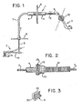
- a controlled member in the form of a clutch 2 is connected by a control cable 3 to an actuation member, in the form of a clutch pedal 4 of an automobile.
- the cable 3 extends through the housing 5 of a self-adjusting mechanism indicated generally at 1.
- the housing 5 itself extends through, and is fixed to, an anchor in the form of a fire wall 6 separating the engine compartment on the left from the passenger compartment on the right.
- the cable 3 extends through a first sleeve part 7 and on the passenger side, the cable 3 extends through a second sleeve part 9.
- One end of the sleeve part 7 is fixed to an anchor 8 whilst the other end is connected to the housing 5 in a way, as will be explained later, that is automatically adjustable to compensate for variations in the length of the cable 3.
- the cable 3 and the sleeve part 7 are curved and sufficiently unrestrained to enable the curvature to change to some extent.
- the clutch pedal 4 To actuate the clutch 2, the clutch pedal 4 is is depressed, so applying an operating tension to the cable 3.
- a pedal return spring 10 serves to return the clutch pedal 4 to an "up" position.
- the clutch 2 includes a lever 12 that controls a clutch spring 13 that normally forces facing plates, not shown, of the clutch into driving engagement with a pressure of 41 Kgm. By depressing pedal 4, tension is exerted upon the control cable 3 which will move the lever 12 to relieve the clutch plates of the force normally exerted by clutch spring 13, allowing gears to be shifted.
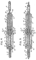
- an end of the sleeve part 7 extends into the housing 5 and the end portion is in the form of a rigid tubular member 20 providing at one end a guide collar 22 onto which an 0 ring 23 that fits within the housing 5 is placed. Beyond the collar 22 the outer surface of the member 20 is serrated at 21.
- the housing 5 has an aperture 25 at one end, through which the first sleeve part 7 extends and an aperture 26 at its opposite end.
- the housing 5 is formed externally with an annular groove 27 in which the fire wall 6 lies to anchor the housing and therefore the self-adjusting mechanism.
- the housing is divided internally by a shoulder 28, the opening through which is defined by a circular wall portion 29 that tapers towards the passage compartment.
- a clutch means 30 including four collet members 31 is adapted to co-operate with serrations 21.
- a collet member 31 is shown in Figure 3 and each has internal serrations 32 which match the serrations 21 and an outer surface 33 which has a taper corresponding to the taper of the wall portion 29.
- the rigid tubular member 20 is surrounded by a first helical spring 35 extending between a loose- fitting collar 36 which bears on an end of the collet members 31 and the shoulder 37 formed by the end of the collar 22. Consequently, the spring 35 will be effective to urge the collets 31 into contact with the tapered wall 29, and the effect of such contact will be to urge the collet members 31 radially inwardly so that the serrations on the inner surface of the cable 31 will engage with the serrations 21.
- a clutch release means in the form of a tubular member 40, is positioned co-axially within housing 5 around control cable 3.
- the tubular member 40 has a shoulder 41 which abuts a flange that defines the opening 26 to prevent the member 40 from being moved out of the housing and also acts as a guide when the member 40 moves within the housing 5.
- the end portion of the member 40 protrudes through the aperture 26 so that the end wall 43 may be abutted by the end of the second sleeve 9.
- the other end of the member 40 abuts the collet members 31.
- First spring means 35 can then become effective to force the outer peripheral surfaces 33 of the collet members into engagement with the tapered wall 29 of the housing, and further axial movement of the collet members in that direction will move them radially inwardly until the serrations of the collet members 31 engage with serrations on the tubular member 21 and so lock. that end of the sleeve part Twith respect to the housing.
- the apparatus that has been described can readily be installed in an existing system.
Landscapes
- Engineering & Computer Science (AREA)
- General Engineering & Computer Science (AREA)
- Health & Medical Sciences (AREA)
- Oral & Maxillofacial Surgery (AREA)
- Mechanical Engineering (AREA)
- Mechanical Operated Clutches (AREA)
- Flexible Shafts (AREA)
Claims (8)
Applications Claiming Priority (2)
| Application Number | Priority Date | Filing Date | Title |
|---|---|---|---|
| US189362 | 1980-09-22 | ||
| US06/189,362 US4344518A (en) | 1980-09-22 | 1980-09-22 | Self-adjusting cable conduit mechanism |
Publications (2)
| Publication Number | Publication Date |
|---|---|
| EP0048620A1 EP0048620A1 (de) | 1982-03-31 |
| EP0048620B1 true EP0048620B1 (de) | 1986-03-19 |
Family
ID=22697002
Family Applications (1)
| Application Number | Title | Priority Date | Filing Date |
|---|---|---|---|
| EP81304331A Expired EP0048620B1 (de) | 1980-09-22 | 1981-09-21 | Bedienungsvorrichtung mit in einer Führungshülle eingelegtem Kabel |
Country Status (4)
| Country | Link |
|---|---|
| US (1) | US4344518A (de) |
| EP (1) | EP0048620B1 (de) |
| DE (1) | DE3174133D1 (de) |
| ES (1) | ES268712Y (de) |
Families Citing this family (38)
| Publication number | Priority date | Publication date | Assignee | Title |
|---|---|---|---|---|
| DE3143765C2 (de) * | 1980-11-07 | 1987-05-14 | Honda Giken Kogyo K.K., Tokio/Tokyo | Automatische Nachstellvorrichtung für einen Betätigungsmechanismus mit einem Betätigungsseil |
| FR2521659B1 (fr) * | 1982-02-15 | 1985-06-21 | Dba | Dispositif de fixation sur une paroi d'une gaine flexible et procede de fixation d'une gaine au moyen d'un tel dispositif |
| EP0118520B1 (de) * | 1982-09-14 | 1989-01-25 | HOYLE, Edgar | Selbstnachstellende kupplungsvorrichtung |
| GB8305495D0 (en) * | 1983-02-28 | 1983-03-30 | Bwp Controls | Cable and sleeve connectors |
| GB8400134D0 (en) * | 1984-01-05 | 1984-02-08 | Hoyle E | Cable control operated clutch mechanism |
| US4784249A (en) * | 1984-10-05 | 1988-11-15 | Lucas Industries | Clutch servos |
| DE3500734A1 (de) * | 1985-01-11 | 1986-07-17 | Daimler-Benz Ag, 7000 Stuttgart | In axialer und radialer richtung gehaltene bundmutter |
| US4598809A (en) * | 1985-01-23 | 1986-07-08 | Bwp Controls | Cable-and-sleeve connector |
| FR2577330B1 (fr) * | 1985-02-13 | 1987-02-20 | Bendix France | Dispositif de commande mecanique a cable a reglage automatique |
| GB8520612D0 (en) * | 1985-08-16 | 1985-09-25 | Bwp Controls Ltd | Cable-&-sleeve connections |
| FR2617920A2 (fr) * | 1985-10-25 | 1989-01-13 | Acco Cables Mans | Dispositif de commande mecanique de cable a reglage manuel |
| FR2589206B1 (fr) * | 1985-10-25 | 1988-04-08 | Bendix France | Dispositif de commande mecanique a cable a reglage manuel |
| FR2595841A1 (fr) * | 1986-01-22 | 1987-09-18 | Bendix France | Dispositif de commande mecanique a cable a reglage automatique |
| DE3602754C1 (en) * | 1986-01-30 | 1987-04-23 | Kuester & Co Gmbh | Bowden pull with automatic length compensation |
| AU584783B2 (en) * | 1986-02-21 | 1989-06-01 | Acco Babcock Inc. | Control cable adjuster device |
| US4799400A (en) * | 1986-02-21 | 1989-01-24 | Acco Babcock Inc. | Self-adjusting cable control device |
| US4682760A (en) * | 1986-09-18 | 1987-07-28 | Acco Babcock Inc. | Constant force cable self adjusting device |
| JPS63195034A (ja) * | 1987-02-06 | 1988-08-12 | Nippon Cable Syst Inc | コントロ−ルケ−ブルの取付装置 |
| US4787263A (en) * | 1987-03-23 | 1988-11-29 | Acco Babcock Inc. | Automatic self-adjusting cable system |
| ES2004442A6 (es) * | 1987-07-02 | 1989-01-01 | Pujol & Tarago | Regulador automatico de la longitud de cables de mando |
| US4798100A (en) * | 1987-09-18 | 1989-01-17 | Babcock Industries Inc. | Automatic adjustment device for cable control systems |
| US4753123A (en) * | 1987-10-14 | 1988-06-28 | Babcock Industries Inc. | Automatic self adjusting cable control device |
| US4854186A (en) * | 1987-12-02 | 1989-08-08 | Kuster & Co. Gmbh | Apparatus for adjusting the length of a bowden cable |
| US4838109A (en) * | 1988-03-04 | 1989-06-13 | Orscheln Co. | Reaction cable assembly including cable slack adjusting means |
| DE3813267A1 (de) * | 1988-04-20 | 1989-11-09 | Kober Ag | Anordnung zur einstellung von bowdenzuegen |
| FR2658763B1 (fr) * | 1990-02-23 | 1992-05-15 | Valeo | Dispositif de commande pour embrayage, notamment pour vehicule automobile. |
| US5058781A (en) * | 1990-10-29 | 1991-10-22 | Aronie Alan B | Caulking gun with drive means which facilitate the immediate release of pressure from the piston |
| GB2260588A (en) * | 1991-10-09 | 1993-04-21 | Rover Group | A clutch cable adjuster |
| DE4412477B4 (de) * | 1994-04-14 | 2006-04-20 | C. Rob. Hammerstein Gmbh | Bowdenzugvorrichtung mit einem Bowdenzug und einer Betätigungsvorrichtung |
| ES2174116T3 (es) * | 1995-11-20 | 2002-11-01 | Kuester & Co Gmbh | Dispositivo para la correccion automatica de la longitud de un cable de traccion. |
| US5842552A (en) * | 1996-12-26 | 1998-12-01 | White Consolidated Industries, Inc. | Self-adjusting drive-control cable for a lawn mower |
| US6193621B1 (en) | 1999-05-06 | 2001-02-27 | Fanuc Robotics North America, Inc. | Take-up device for tensioning motion transmitting control cables |
| ES2188394B1 (es) * | 2001-09-17 | 2004-03-16 | Castellon Melchor Daumal | Cable de control de tension autoajustable |
| FR2857716B1 (fr) * | 2003-07-18 | 2005-09-09 | Arvinmeritor Light Vehicle Sys | Tendeur de cable de leve-vitre |
| FR2864184B1 (fr) * | 2003-12-19 | 2006-03-03 | Arvinmeritor Light Vehicle Sys | Tendeur de cable |
| CN103277424B (zh) * | 2013-06-28 | 2015-11-18 | 重庆长安汽车股份有限公司 | 一种汽车离合器分离系统 |
| JP2017072177A (ja) * | 2015-10-06 | 2017-04-13 | 株式会社ハイレックスコーポレーション | コントロールケーブル |
| US10151339B2 (en) * | 2017-05-15 | 2018-12-11 | Hsin Chong Machinery Works Co. Ltd. | Cable length automatic adjustment device for vehicle window lifter |
Family Cites Families (8)
| Publication number | Priority date | Publication date | Assignee | Title |
|---|---|---|---|---|
| US1804309A (en) * | 1930-04-10 | 1931-05-05 | Bourbeau Olivier | Automatic brake adjusting mechanism |
| US2788095A (en) * | 1953-07-29 | 1957-04-09 | Gen Motors Corp | Automatic wear adjustor |
| US3194349A (en) * | 1963-03-06 | 1965-07-13 | Lambert & Brake Corp | Wedge operated spot brake |
| FR1378988A (fr) * | 1963-10-07 | 1964-11-20 | Isothermos Sa | Régleur de frein notamment pour matériel ferroviaire |
| FR2278982A1 (fr) * | 1974-03-19 | 1976-02-13 | Huret Roger | Dispositif de rattrapage du jeu dans une transmission par cable |
| US4057135A (en) * | 1975-09-19 | 1977-11-08 | Aisin Seiki Kabushiki Kaisha | Self-adjusting release mechanism for a clutch assembly |
| FR2420164A1 (fr) * | 1978-03-17 | 1979-10-12 | Ferodo Sa | Dispositif compensateur pour tringlerie de transmission |
| FR2470994A1 (fr) * | 1979-12-07 | 1981-06-12 | Dba | Commande mecanique par cable coulissant axialement dans une gaine flexible |
-
1980
- 1980-09-22 US US06/189,362 patent/US4344518A/en not_active Expired - Lifetime
-
1981
- 1981-09-21 DE DE8181304331T patent/DE3174133D1/de not_active Expired
- 1981-09-21 EP EP81304331A patent/EP0048620B1/de not_active Expired
- 1981-09-21 ES ES1981268712U patent/ES268712Y/es not_active Expired
Also Published As
| Publication number | Publication date |
|---|---|
| DE3174133D1 (en) | 1986-04-24 |
| EP0048620A1 (de) | 1982-03-31 |
| ES268712U (es) | 1983-06-01 |
| ES268712Y (es) | 1983-12-01 |
| US4344518A (en) | 1982-08-17 |
Similar Documents
| Publication | Publication Date | Title |
|---|---|---|
| EP0048620A1 (de) | Bedienungsvorrichtung mit in einer Führungshülle eingelegtem Kabel | |
| US4598809A (en) | Cable-and-sleeve connector | |
| EP0120616B1 (de) | Kupplung von Kabel und Hülle | |
| US4378713A (en) | Self-adjusting cable control device | |
| JPS6248097B2 (de) | ||
| US4304322A (en) | Compensating device for a transmission linkage | |
| US4799400A (en) | Self-adjusting cable control device | |
| US4690262A (en) | Clutch control cable with auto-adjuster | |
| US4892004A (en) | Automatic length adjuster for control cables | |
| EP0213857B1 (de) | Seilzug aus Kabel und Führungshülle | |
| US20160258474A1 (en) | Cable Connection Apparatus for Vehicles | |
| US3788438A (en) | Clutch actuating mechanism with automatically determined free play | |
| GB2176861A (en) | Device for automatically regulating tension applied to inner wire of control cable for slack adjustment | |
| US5138897A (en) | Cable adjuster | |
| US5139126A (en) | Control device for a clutch, in particular for an automotive vehicle | |
| US5386887A (en) | Brake-adjusting system, especially for motor vehicles | |
| KR960005844B1 (ko) | 스프링 브레이크 작동자의 작동 기능 정지 및 자동 복귀장치 | |
| GB2081411A (en) | Flexible control cable | |
| US4424890A (en) | Manual clutch wear adjuster | |
| US4429777A (en) | Automatic locking and adjustment assembly | |
| WO1993007397A1 (en) | A clutch cable adjuster | |
| EP0370685B1 (de) | Kabel-Justiervorrichtung | |
| US4549709A (en) | Device for attaching to a wall the end of a sheath in which a control cable is slidably received | |
| EP0556064A2 (de) | Bowdenzug | |
| JPH0218341Y2 (de) |
Legal Events
| Date | Code | Title | Description |
|---|---|---|---|
| PUAI | Public reference made under article 153(3) epc to a published international application that has entered the european phase |
Free format text: ORIGINAL CODE: 0009012 |
|
| AK | Designated contracting states |
Designated state(s): DE FR GB IT |
|
| 17P | Request for examination filed |
Effective date: 19820927 |
|
| GRAA | (expected) grant |
Free format text: ORIGINAL CODE: 0009210 |
|
| AK | Designated contracting states |
Kind code of ref document: B1 Designated state(s): DE FR GB IT |
|
| REF | Corresponds to: |
Ref document number: 3174133 Country of ref document: DE Date of ref document: 19860424 |
|
| ITF | It: translation for a ep patent filed | ||
| ET | Fr: translation filed | ||
| PLBE | No opposition filed within time limit |
Free format text: ORIGINAL CODE: 0009261 |
|
| STAA | Information on the status of an ep patent application or granted ep patent |
Free format text: STATUS: NO OPPOSITION FILED WITHIN TIME LIMIT |
|
| 26N | No opposition filed | ||
| ITTA | It: last paid annual fee | ||
| PGFP | Annual fee paid to national office [announced via postgrant information from national office to epo] |
Ref country code: FR Payment date: 19990909 Year of fee payment: 19 |
|
| PGFP | Annual fee paid to national office [announced via postgrant information from national office to epo] |
Ref country code: GB Payment date: 19990915 Year of fee payment: 19 |
|
| PGFP | Annual fee paid to national office [announced via postgrant information from national office to epo] |
Ref country code: DE Payment date: 19990927 Year of fee payment: 19 |
|
| PG25 | Lapsed in a contracting state [announced via postgrant information from national office to epo] |
Ref country code: GB Free format text: LAPSE BECAUSE OF NON-PAYMENT OF DUE FEES Effective date: 20000921 |
|
| GBPC | Gb: european patent ceased through non-payment of renewal fee |
Effective date: 20000921 |
|
| PG25 | Lapsed in a contracting state [announced via postgrant information from national office to epo] |
Ref country code: FR Free format text: LAPSE BECAUSE OF NON-PAYMENT OF DUE FEES Effective date: 20010531 |
|
| PG25 | Lapsed in a contracting state [announced via postgrant information from national office to epo] |
Ref country code: DE Free format text: LAPSE BECAUSE OF NON-PAYMENT OF DUE FEES Effective date: 20010601 |
|
| REG | Reference to a national code |
Ref country code: FR Ref legal event code: ST |