EP0048657A1 - Schutzvorrichtung für mit Wechselspannung gespeiste elektrische Apparate - Google Patents
Schutzvorrichtung für mit Wechselspannung gespeiste elektrische Apparate Download PDFInfo
- Publication number
- EP0048657A1 EP0048657A1 EP19810401405 EP81401405A EP0048657A1 EP 0048657 A1 EP0048657 A1 EP 0048657A1 EP 19810401405 EP19810401405 EP 19810401405 EP 81401405 A EP81401405 A EP 81401405A EP 0048657 A1 EP0048657 A1 EP 0048657A1
- Authority
- EP
- European Patent Office
- Prior art keywords
- signal
- microprocessor
- counter
- alternating
- alternating signal
- Prior art date
- Legal status (The legal status is an assumption and is not a legal conclusion. Google has not performed a legal analysis and makes no representation as to the accuracy of the status listed.)
- Granted
Links
- 230000001681 protective effect Effects 0.000 title claims description 5
- 230000010363 phase shift Effects 0.000 claims description 7
- 238000012545 processing Methods 0.000 claims description 6
- 238000007493 shaping process Methods 0.000 claims 1
- 238000012546 transfer Methods 0.000 abstract description 2
- 238000005259 measurement Methods 0.000 description 6
- 239000004020 conductor Substances 0.000 description 4
- 238000001514 detection method Methods 0.000 description 2
- 230000011664 signaling Effects 0.000 description 2
- 240000008042 Zea mays Species 0.000 description 1
- 239000003990 capacitor Substances 0.000 description 1
- 238000011161 development Methods 0.000 description 1
- 238000010586 diagram Methods 0.000 description 1
- 238000001914 filtration Methods 0.000 description 1
- 238000010348 incorporation Methods 0.000 description 1
- 238000012544 monitoring process Methods 0.000 description 1
- 230000008054 signal transmission Effects 0.000 description 1
- 230000003068 static effect Effects 0.000 description 1
- 238000011144 upstream manufacturing Methods 0.000 description 1
Images

Classifications
-
- H—ELECTRICITY
- H02—GENERATION; CONVERSION OR DISTRIBUTION OF ELECTRIC POWER
- H02H—EMERGENCY PROTECTIVE CIRCUIT ARRANGEMENTS
- H02H3/00—Emergency protective circuit arrangements for automatic disconnection directly responsive to an undesired change from normal electric working condition with or without subsequent reconnection ; integrated protection
- H02H3/08—Emergency protective circuit arrangements for automatic disconnection directly responsive to an undesired change from normal electric working condition with or without subsequent reconnection ; integrated protection responsive to excess current
- H02H3/093—Emergency protective circuit arrangements for automatic disconnection directly responsive to an undesired change from normal electric working condition with or without subsequent reconnection ; integrated protection responsive to excess current with timing means
- H02H3/0935—Emergency protective circuit arrangements for automatic disconnection directly responsive to an undesired change from normal electric working condition with or without subsequent reconnection ; integrated protection responsive to excess current with timing means the timing being determined by numerical means
-
- H—ELECTRICITY
- H02—GENERATION; CONVERSION OR DISTRIBUTION OF ELECTRIC POWER
- H02H—EMERGENCY PROTECTIVE CIRCUIT ARRANGEMENTS
- H02H3/00—Emergency protective circuit arrangements for automatic disconnection directly responsive to an undesired change from normal electric working condition with or without subsequent reconnection ; integrated protection
- H02H3/46—Emergency protective circuit arrangements for automatic disconnection directly responsive to an undesired change from normal electric working condition with or without subsequent reconnection ; integrated protection responsive to frequency deviations
Definitions
- the invention relates to a protection device for an alternating current supply circuit comprising a detector associated with the supply circuit for emitting an alternating signal representative of the current flowing through the supply circuit.
- the power supply or electrical distribution circuits include protection devices automatically signaling or isolating, for example by tripping a circuit breaker, the overloaded or faulty parts in order to avoid extension of the fault to the entire circuit.
- Protection circuit breakers are generally equipped with a thermal and electromagnetic trip device incorporated in the device, but the performance of these trip devices is limited.
- the static releases recently proposed for large size circuit breakers are complicated and expensive. Protection can also be provided by monitoring relays which control control devices to remedy the fault, but these systems use a large number of components and links whose reliability is not absolute.
- the present invention aims to remedy these drawbacks and allow the realization of a simple and efficient electronic device which can be associated directly with a circuit breaker or any other protective device.
- the protection device is characterized in that it further comprises an interface for transferring said alternating signal to a microprocessor to cause an interruption of the microprocessor when the signal crosses zero, a time base, notably frequency higher than that of the AC signal, driving the microprocessor and a programmable counter including the content is decremented at each stroke of the time base, the microprocessor reading the content of said counter during the program for processing said interruption to generate from the readings of the counter a protective action.
- the device according to the invention makes use of a microprocessor whose performance is well known to specialists, associated with a counter controlled by the zero crossings of the signal representative of the alternating current.
- This basic assembly can be arranged to monitor the frequency of the alternating signal by measuring the time elapsed between two successive zero crossings by simply subtracting the contents of the counter at the instants of these two zero crossings.
- the microprocessor generates the protection signal which can be an indicator signal or an automatic control signal, for example actuation of a protection device.
- the device can manage several channels, each for example assigned to one of the phases of the circuit, or one being assigned to the intensity and the other to the voltage of a current, by using a signal transfer interface. with multiple entries.
- a detector for example a current transformer, supplies an alternating signal of the same frequency and of instantaneous amplitude proportional to the amplitude of the current flowing through the associated phase conductor.
- the AC signals are formatted as square signals. These act on an interface managed by the microprocessor. Each edge or every other edge) of the square signal causes an interruption of the microprocessor. This one deviates from its main program and deals with this interruption. This processing consists in reading by interrogating the interface which is the channel which caused the interruption, that is to say the channel whose signal has just passed to zero.
- the microprocessor then reads the content of the counter.
- This device can be applied to a relay for switching on capacitor banks for adjusting the cos ⁇ , to active or reactive power measurement relays and / or to directional relays.
- the device is arranged for detection of the maximum amplitude to ensure automatic tripping of a circuit breaker when this maximum amplitude exceeds a predetermined threshold.
- a counter is decremented at each stroke of the time base. At zero crossing, the counter is loaded using the microprocessor with a binary value such that this counter reaches zero at the moment later. When the counter reaches zero, it causes an interruption of the microprocessor.
- the device can be applied to overload, overcurrent, undercurrent, power, etc. relays, and generally to any relay where measurement of the signal amplitude is necessary.
- Signal filtering can be performed upstream of the interface and the analog-to-digital converter and in this case the maximum value of the signal emitted by the converted analog digital seur intervenes well at the instant * after the zero crossing of the signal.
- the signal transmission circuit to the analog-to-digital converter comprises a component, for example a filter introducing a phase shift of the signal, this component being absent in the circuit towards the interface, it is of course advisable to take this phase shift into account and carry out the measurement. instant value at the moment + delay brought by the filter.
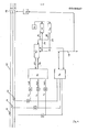
- a three-phase circuit 10 for example the network, is protected by a circuit breaker 12 having a tripping control device 14 in the event of an overload or a fault to interrupt the supply of the load.
- Each conductor of circuit 10 is associated with a current transformer 16, 18, 20 which delivers an alternating signal representative of the current flowing through the corresponding conductor.
- Each AC signal is filtered in a low pass filter 22, 24, 26 retaining only the harmonic 1 and shaped in a block 28, 30, 32, so as to obtain square slots whose state changes are perform at signal zero crossings.
- the square signals pass through an interface 34 of a microprocessor 36 to request an interruption 35 from the microprocessor 36 at each passage to zero of one of the signals.
- the program for processing this interrupt causes an interrogation 40 of the interface 34 to find out which analog channel has requested the interrupt, that is to say what is the signal 16, 18, 20, which has just go to zero.
- the microprocessor 36 manages two programmable counters 42, 44, both controlled by a time base 46 of frequency much higher than that of the network 10. The content of the counters 42, 44 is decremented at each stroke of the time base 46.
- the counters 42, 44 are connected at 50, 52 to a data bus 48 of the microprocessor and can request by the links 54, 56 an interruption of the microprocessor 36.
- the data bus 48 is connected to the trip control 14.
- the device described can constitute a minimum or maximum frequency relay or a frequency-metric load shedding relay.
- Microprocessor 36 can be programmed to read the con held by the counter 42 at the zero crossing of each of the alternating signals and to subtract the value read from the counter at the zero crossing t l (fig. 3) of one of the signals s 1 from the value read from the counter at the zero crossing t 2 of another of said signals s 2 to determine the phase shift between the two signals sI and s 2 .
- the microprocessor 36 will measure the phase difference between the currents in the different conductors of the circuit 10, but it is understood that the measured phase difference can correspond to different values of the same current, for example the voltage and intensity.
- FIG. 4 schematically illustrates such a variant in which one of the signals is supplied by a current transformer 58 and represents the intensity of the current in a circuit 60 and the other of the signals is supplied by a potential transformer 62 and represents the voltage in the circuit 60.
- the microprocessor 36 measures the phase shift between the two signals as described above. Referring again to FIG. 1, it can be seen that the outputs of the filters 22, 24, 26 are connected - to an analog to digital converter 64 which provides
- the analog-to-digital converter 64 allows a measurement of the peak amplitude of a signal. Referring to FIG. 2, it can be seen that the peak amplitude of a sinusoidal signal is present at the instant T / 4 after the signal has gone to zero, T being the period of the signal.
- the interruption of the microprocessor 36 requested by the interface 34 causes a load of the counter 44 with a binary lace value that the counter 44 arrives at zero by decrementation at each stroke of the time base 46, at instant ⁇ .
- the counter 44 reaches zero it causes an interruption of the microprocessor 36 which reads the instantaneous value of the corresponding signal in the analog to digital converter 64. If the signal has been correctly filtered this value corresponds to the peak value and a comparison to a threshold value pre-determined allows the detection of an overload or a fault and the tripping command of the circuit breaker 12.
- the device illustrated in FIG. 1 can be simplified when only the peak amplitude of the signal has to be measured.
- the microprocessor can be arranged to perform other operations, in particular counting without departing from the scope of the invention, and it can control any other operation, in particular for signaling or closing an apparatus.
- the device is simple and compact enough for incorporation into protective devices such as low voltage or medium voltage circuit breakers.
- the advantage of the inventive device is that it makes little use of the microprocessor for the acquisition of the frequency, of the phase shifts of the amplitudes of the alternative channels, these acquisitions occurring during interruptions.
- the microprocessor is thus available to carry out programs for processing this data and / or to carry out other programs.
Landscapes
- Emergency Protection Circuit Devices (AREA)
- Measurement Of Current Or Voltage (AREA)
Applications Claiming Priority (2)
| Application Number | Priority Date | Filing Date | Title |
|---|---|---|---|
| FR8020294A FR2490889A1 (fr) | 1980-09-19 | 1980-09-19 | Dispositif de protection d'appareils electriques alimentes en courant alternatif |
| FR8020294 | 1980-09-19 |
Publications (3)
| Publication Number | Publication Date |
|---|---|
| EP0048657A1 true EP0048657A1 (de) | 1982-03-31 |
| EP0048657B1 EP0048657B1 (de) | 1985-04-10 |
| EP0048657B2 EP0048657B2 (de) | 1989-04-05 |
Family
ID=9246142
Family Applications (1)
| Application Number | Title | Priority Date | Filing Date |
|---|---|---|---|
| EP19810401405 Expired EP0048657B2 (de) | 1980-09-19 | 1981-09-10 | Schutzvorrichtung für mit Wechselspannung gespeiste elektrische Apparate |
Country Status (4)
| Country | Link |
|---|---|
| EP (1) | EP0048657B2 (de) |
| JP (2) | JPS5783114A (de) |
| DE (1) | DE3169847D1 (de) |
| FR (1) | FR2490889A1 (de) |
Families Citing this family (1)
| Publication number | Priority date | Publication date | Assignee | Title |
|---|---|---|---|---|
| JP2500464B2 (ja) * | 1993-06-30 | 1996-05-29 | 日本電気株式会社 | アンテナ装置 |
Citations (3)
| Publication number | Priority date | Publication date | Assignee | Title |
|---|---|---|---|---|
| US3529215A (en) * | 1967-10-02 | 1970-09-15 | Hathaway Instr Inc | Digital off frequency relay |
| US3993984A (en) * | 1975-04-08 | 1976-11-23 | Power Management Corporation | Electronic underfrequency relay |
| FR2344159A1 (fr) * | 1976-03-09 | 1977-10-07 | Licentia Gmbh | Declencheur a maximum de courant numerique |
Family Cites Families (3)
| Publication number | Priority date | Publication date | Assignee | Title |
|---|---|---|---|---|
| JPS508041A (de) * | 1973-05-25 | 1975-01-28 | ||
| JPS5024749A (de) * | 1973-07-02 | 1975-03-17 | ||
| JPS5036171A (de) * | 1973-08-01 | 1975-04-05 |
-
1980
- 1980-09-19 FR FR8020294A patent/FR2490889A1/fr active Granted
-
1981
- 1981-09-10 EP EP19810401405 patent/EP0048657B2/de not_active Expired
- 1981-09-10 DE DE8181401405T patent/DE3169847D1/de not_active Expired
- 1981-09-14 JP JP56145387A patent/JPS5783114A/ja active Pending
-
1989
- 1989-10-30 JP JP12710889U patent/JPH0265037U/ja active Pending
Patent Citations (3)
| Publication number | Priority date | Publication date | Assignee | Title |
|---|---|---|---|---|
| US3529215A (en) * | 1967-10-02 | 1970-09-15 | Hathaway Instr Inc | Digital off frequency relay |
| US3993984A (en) * | 1975-04-08 | 1976-11-23 | Power Management Corporation | Electronic underfrequency relay |
| FR2344159A1 (fr) * | 1976-03-09 | 1977-10-07 | Licentia Gmbh | Declencheur a maximum de courant numerique |
Also Published As
| Publication number | Publication date |
|---|---|
| FR2490889A1 (fr) | 1982-03-26 |
| EP0048657B1 (de) | 1985-04-10 |
| FR2490889B1 (de) | 1984-03-16 |
| EP0048657B2 (de) | 1989-04-05 |
| JPS5783114A (en) | 1982-05-24 |
| JPH0265037U (de) | 1990-05-16 |
| DE3169847D1 (en) | 1985-05-15 |
Similar Documents
| Publication | Publication Date | Title |
|---|---|---|
| EP0297933B1 (de) | Anordnung zur Kontrolle und zur Messung der Isolierung eines elektrischen Netzes | |
| US4300182A (en) | Metering and protection system for an A.C. power system | |
| FR2649554A1 (fr) | Disjoncteur electronique utilisant un circuit numerique qui presente une possibilite de declenchement instantane | |
| EP2820433B1 (de) | Elektrizitätszähler und verfahren zur feststellung des zustandes eines schutzschalters einer mit diesem zähler verbundenen vorrichtung | |
| EP0603088B1 (de) | Vorrichtung zur numerischen Berechnung einer symmetrischen Komponente einer elektrischen Grösse eines Dreiphasennetzes und damit versehenes Relais | |
| EP2849195B1 (de) | Zusatzvorrichung für elektrischen Schutzschalter, elektrisches System mit einem Schutzschalter und dieser Zusatzvorrichtung und Verfahren zur Bestimmung des Grunds der Öffnung des Schutzshalters dank dieser Zusatzvorrichtung | |
| NZ197780A (en) | Earth leakage detection by digital sampling of current difference in live and neutral lines | |
| EP0048657B1 (de) | Schutzvorrichtung für mit Wechselspannung gespeiste elektrische Apparate | |
| EP0568471A1 (de) | Einrichtung zur Überwachung eines homopolaren Fehlers im Stromnetz | |
| EP3009851B1 (de) | Zähler zum aufdecken von betrug durch bypass | |
| EP0524300A1 (de) | Vorrichtung zum schutz von elektrischen geräten, maschinen und anlagen | |
| EP0428601A1 (de) | Anordnung zur messung von teilentladungen. | |
| FR2700076A1 (fr) | Déclencheur électronique comportant un dispositif de test. | |
| EP1385249B1 (de) | Vorrichtung und Verfahren zum Überstromschutz in einem elektrischen Energieverteilungsschrank | |
| FR2665584A1 (fr) | Declencheur electronique a fonction court retard. | |
| FR3032276A1 (fr) | Capteur de courant et reseau electrique comprenant un tel capteur de courant | |
| EP0851553B1 (de) | Elektronischer Auslöser mit, in Reihe geschalten, einem nichtrekursivem und einem rekursivem Filter | |
| FR2745911A1 (fr) | Dispositif multifonctions pour proteger, mesurer, compter, surveiller les parametres physiques d'une installation electrique industrielle | |
| EP1083644B1 (de) | Lichtbogenstromsensitiver Erdfehlerschutz, Auslöser und Schutzschalter mit einer solchen Vorrichtung | |
| FR2745910A1 (fr) | Dispositif multifonctions pour mesurer des parametres physiques d'une installation electrique basse tension en regime alternatif | |
| EP3015873B1 (de) | Detektionsverfahren eines betrügerischen by-pass-versuchs an einem zähler | |
| FR2522824A1 (fr) | Dispositif pour appliquer des signaux logiques de test a deux etats sur une entree d'un circuit logique et application aux tests automatiques d'une pluralite de circuits logiques | |
| FR2638583A1 (fr) | Declencheur a microprocesseur comportant des moyens de calcul de la valeur efficace du courant | |
| FR2686701A1 (fr) | Dispositif de mesure de grandeurs electriques. | |
| EP0161620B1 (de) | Einrichtung zur Ausgabe eines Fehlersignals für eine elektrische Schaltung am Netz |
Legal Events
| Date | Code | Title | Description |
|---|---|---|---|
| PUAI | Public reference made under article 153(3) epc to a published international application that has entered the european phase |
Free format text: ORIGINAL CODE: 0009012 |
|
| AK | Designated contracting states |
Designated state(s): BE CH DE GB IT NL SE |
|
| 17P | Request for examination filed |
Effective date: 19820617 |
|
| ITF | It: translation for a ep patent filed | ||
| GRAA | (expected) grant |
Free format text: ORIGINAL CODE: 0009210 |
|
| AK | Designated contracting states |
Designated state(s): BE CH DE GB IT LI NL SE |
|
| REF | Corresponds to: |
Ref document number: 3169847 Country of ref document: DE Date of ref document: 19850515 |
|
| PLBI | Opposition filed |
Free format text: ORIGINAL CODE: 0009260 |
|
| 26 | Opposition filed |
Opponent name: BBC AKTIENGESELLSCHAFT BROWN,BOVERI & CIE. Effective date: 19851227 |
|
| NLR1 | Nl: opposition has been filed with the epo |
Opponent name: BBC AKTIENGESELLSCHAFT BROWN,BOVERI & CIE. |
|
| ITF | It: translation for a ep patent filed | ||
| PUAH | Patent maintained in amended form |
Free format text: ORIGINAL CODE: 0009272 |
|
| STAA | Information on the status of an ep patent application or granted ep patent |
Free format text: STATUS: PATENT MAINTAINED AS AMENDED |
|
| 27A | Patent maintained in amended form |
Effective date: 19890405 |
|
| AK | Designated contracting states |
Kind code of ref document: B2 Designated state(s): BE CH DE GB IT NL SE |
|
| NLR2 | Nl: decision of opposition | ||
| NLR3 | Nl: receipt of modified translations in the netherlands language after an opposition procedure | ||
| ITTA | It: last paid annual fee | ||
| PGFP | Annual fee paid to national office [announced via postgrant information from national office to epo] |
Ref country code: GB Payment date: 19920828 Year of fee payment: 12 |
|
| PGFP | Annual fee paid to national office [announced via postgrant information from national office to epo] |
Ref country code: SE Payment date: 19920914 Year of fee payment: 12 |
|
| PGFP | Annual fee paid to national office [announced via postgrant information from national office to epo] |
Ref country code: CH Payment date: 19920918 Year of fee payment: 12 |
|
| PGFP | Annual fee paid to national office [announced via postgrant information from national office to epo] |
Ref country code: DE Payment date: 19920923 Year of fee payment: 12 |
|
| PGFP | Annual fee paid to national office [announced via postgrant information from national office to epo] |
Ref country code: NL Payment date: 19920930 Year of fee payment: 12 |
|
| PGFP | Annual fee paid to national office [announced via postgrant information from national office to epo] |
Ref country code: BE Payment date: 19921028 Year of fee payment: 12 |
|
| PG25 | Lapsed in a contracting state [announced via postgrant information from national office to epo] |
Ref country code: GB Effective date: 19930910 |
|
| PG25 | Lapsed in a contracting state [announced via postgrant information from national office to epo] |
Ref country code: SE Effective date: 19930911 |
|
| PG25 | Lapsed in a contracting state [announced via postgrant information from national office to epo] |
Ref country code: LI Effective date: 19930930 Ref country code: CH Effective date: 19930930 Ref country code: BE Effective date: 19930930 |
|
| BERE | Be: lapsed |
Owner name: MERLIN GERIN Effective date: 19930930 |
|
| PG25 | Lapsed in a contracting state [announced via postgrant information from national office to epo] |
Ref country code: NL Effective date: 19940401 |
|
| GBPC | Gb: european patent ceased through non-payment of renewal fee |
Effective date: 19930910 |
|
| NLV4 | Nl: lapsed or anulled due to non-payment of the annual fee | ||
| REG | Reference to a national code |
Ref country code: CH Ref legal event code: PL |
|
| PG25 | Lapsed in a contracting state [announced via postgrant information from national office to epo] |
Ref country code: DE Effective date: 19940601 |
|
| EUG | Se: european patent has lapsed |
Ref document number: 81401405.6 Effective date: 19940410 |