EP0851553B1 - Elektronischer Auslöser mit, in Reihe geschalten, einem nichtrekursivem und einem rekursivem Filter - Google Patents
Elektronischer Auslöser mit, in Reihe geschalten, einem nichtrekursivem und einem rekursivem Filter Download PDFInfo
- Publication number
- EP0851553B1 EP0851553B1 EP97410136A EP97410136A EP0851553B1 EP 0851553 B1 EP0851553 B1 EP 0851553B1 EP 97410136 A EP97410136 A EP 97410136A EP 97410136 A EP97410136 A EP 97410136A EP 0851553 B1 EP0851553 B1 EP 0851553B1
- Authority
- EP
- European Patent Office
- Prior art keywords
- trip device
- filter
- current
- sampling
- samples
- Prior art date
- Legal status (The legal status is an assumption and is not a legal conclusion. Google has not performed a legal analysis and makes no representation as to the accuracy of the status listed.)
- Expired - Lifetime
Links
- 238000005070 sampling Methods 0.000 claims description 31
- 230000007935 neutral effect Effects 0.000 claims description 7
- 238000001914 filtration Methods 0.000 claims description 5
- 239000004020 conductor Substances 0.000 claims description 3
- 230000002238 attenuated effect Effects 0.000 description 2
- 238000009434 installation Methods 0.000 description 2
- 230000001934 delay Effects 0.000 description 1
- 238000010586 diagram Methods 0.000 description 1
- 235000021183 entrée Nutrition 0.000 description 1
- 238000010438 heat treatment Methods 0.000 description 1
- 238000005259 measurement Methods 0.000 description 1
Images




Classifications
-
- H—ELECTRICITY
- H03—ELECTRONIC CIRCUITRY
- H03H—IMPEDANCE NETWORKS, e.g. RESONANT CIRCUITS; RESONATORS
- H03H17/00—Networks using digital techniques
- H03H17/02—Frequency selective networks
- H03H17/0283—Filters characterised by the filter structure
- H03H17/0286—Combinations of filter structures
- H03H17/0288—Recursive, non-recursive, ladder, lattice structures
-
- H—ELECTRICITY
- H02—GENERATION; CONVERSION OR DISTRIBUTION OF ELECTRIC POWER
- H02H—EMERGENCY PROTECTIVE CIRCUIT ARRANGEMENTS
- H02H3/00—Emergency protective circuit arrangements for automatic disconnection directly responsive to an undesired change from normal electric working condition with or without subsequent reconnection ; integrated protection
- H02H3/08—Emergency protective circuit arrangements for automatic disconnection directly responsive to an undesired change from normal electric working condition with or without subsequent reconnection ; integrated protection responsive to excess current
- H02H3/093—Emergency protective circuit arrangements for automatic disconnection directly responsive to an undesired change from normal electric working condition with or without subsequent reconnection ; integrated protection responsive to excess current with timing means
- H02H3/0935—Emergency protective circuit arrangements for automatic disconnection directly responsive to an undesired change from normal electric working condition with or without subsequent reconnection ; integrated protection responsive to excess current with timing means the timing being determined by numerical means
Definitions
- the invention relates to an electronic trip device connected to means for measuring the current flowing in a polyphase electrical network to be protected and comprising means for sampling current signals supplied by the measuring means, means for calculation, connected to the sampling means and calculating a quantity representative of the thermal state of the network, and means for comparing said quantity with thresholds of predetermined triggering, the calculation means comprising first means of filtering, of the finite impulse response filter type, receiving the signal samples current and providing signals representative of the rms value of the current.
- a digital response filter is used infinite pulse (IIR) in order to model the thermal state of the installation. If the sampling frequency is high enough, the results obtained are satisfactory. For example, a filter of this type proves satisfactory for a frequency sampling rate of 1600 Hz for conventional networks at 50 Hz, 60 Hz or 400 Hz. against, if you want to use a cheap microprocessor, which means limiting the sampling frequency, the results obtained are not satisfactory with regard to concerns the accuracy of the measurement.
- the object of the invention is a cheap trigger enabling results to be obtained satisfactory for both filtering and modeling of the thermal state.
- this object is achieved by a trigger according to claim 1.
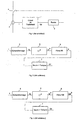
- the trigger comprises a processing circuit 1, with microprocessor, receiving as input signals representative of the current I flowing in an electrical network to protect.
- the electrical network is shown schematically in the form of a single-phase network and a current sensor 2 provides the trip unit with the signals I.
- the processing 1 provides, possibly after an appropriate time delay, Sd signals of tripping to a relay 3 which causes the opening of a circuit breaker 4 and the interruption of current flow in the network.
- the particular embodiment of the processing circuit according to the prior art illustrated in the Figure 2 includes a digital filter 5 with infinite impulse response, or IIR filter.
- the current signals I are applied to the input of a sampling circuit 6 which provides output of current samples Ik.
- the input of the IIR filter is connected to the output of the sampling circuit 6 via a squaring circuit 8.
- the ⁇ output signals from the IIR filter are representative of the thermal state of the network and are applied to the input of a circuit 7 for comparison with trigger thresholds.
- the circuit 7 possibly includes time delays and provides a trigger signal Sd if the quantity ⁇ is greater than a predetermined threshold for the duration of the time delay corresponding.
- the output of the sampling circuit 6 is connected to the input of a squaring circuit 8, the output of which is connected to the input of a digital filter 9 with finite impulse response, or FIR filter.
- the output signals of the FIR filter 9 are representative of the square Ieff 2 of the rms value of the current flowing in the network.
- the comparison circuit 7 provides a trigger signal if the square of the rms value of the current is greater than a predetermined threshold during the duration of the corresponding time delay.
- the frequency response of the transfer function K1 of the IIR filter 5 in FIG. 2 is illustrated in FIG. 4 for a sampling frequency of 1600 Hz.
- the IIR filter 5 remakes the calculation of a new value ⁇ k of ⁇ for each sample Ik from the value of ⁇ k -1 previously calculated and the new sample Ik.
- the frequency response K1 is acceptable because it correctly attenuates both harmonics of 50 Hz, than those of 60 Hz and those of 400 Hz.
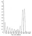
- FIG. 5 represents the frequency response of the transfer function K2 of the FIR filter 9 of FIG. 3, for a sampling frequency of 800 Hz and an effective value calculation using 16 samples.
- an offset period td of a few milliseconds, 1.9 ms in the embodiment shown, is added to the sampling period Te after each group of 8 samples. Such an offset makes it possible to effectively filter both the harmonics of 50 Hz and those of 60 Hz.
- the transfer function K2 is of the form:
- Harmonic attenuation can be considered satisfactory with frequency sampling frequency, 800 Hz, lower than the associated sampling frequency at K1.
- the circuit according to Figure 3 does not allow to take into account the actual heating of the network conductors. We also get different results, depending on whether the circuit according to FIG. 2 or according to FIG. 3 is used.
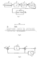
- the processing circuit according to FIG. 7 includes an FIR filter 9 and an IIR filter 5 in series between the circuit 8 of squared elevation and the circuit of comparison 7.
- the FIR filter 9 calculates a new value Ieff 2 i of the square Ieff 2 of the effective value of the current after each group of 9 successive samples, using the last 18 samples, that is to say a number of samples double that included between two successive shifts.
- This period Te1 corresponds to a sampling frequency Fe 1 ⁇ Fe at the input of the filter IIR 5.
- the latter calculates a new value ⁇ i of ⁇ with each new calculation of Ieff 2 , that is to say with the frequency Fe1, close to 80 Hz.
- the transfer function K'1 of the IIR filter 5 of FIG. 7 is of the form:
- Such a transfer function can be performed, as illustrated in FIG. 9.
- the value Ieff 2 i is applied to an input "+" of an operator 10 which receives on an input "-” the value ⁇ i-1 previously calculated and stored in a circuit 11.
- the difference Ieff 2 i - ⁇ i-1 is applied to the input of an operator 12 which multiplies it by the constant ⁇ 2.
- the product ⁇ 2 (Ieff 2 i - ⁇ i-1) is applied to an input "+” of an operator 13 which receives on another input "+” the value ⁇ i-1.
- the circuit for processing a trip device associated with a three-phase network with neutral comprises a sampler 6, a circuit 8 elevation squared and a FIR filter 9 associated with each phase ⁇ 1, ⁇ 2, ⁇ 3 and neutral N.
- a circuit 14 maximum is connected to the output of the FIR filters 9. It provides at the output signals representative of the square of the rms value of the highest current taken from among the phase currents I ⁇ 1, I ⁇ 2, I ⁇ 3 and neutral IN.
- the trigger has a single filter IIR 5, connected to the output of circuit 14 and a comparison circuit 7 connected to the output of filter 5. This gives a good cost / precision compromise.
- the FIR filter 9 associated with this driver may be omitted.
Landscapes
- Physics & Mathematics (AREA)
- Engineering & Computer Science (AREA)
- Computer Hardware Design (AREA)
- Mathematical Physics (AREA)
- Measurement Of Current Or Voltage (AREA)
- Emergency Protection Circuit Devices (AREA)
Claims (8)
- Elektronischer Auslöser, der an Meßmittel (2) zur Messung des Stroms in einem zu schützenden, mehrphasigen Leitungsnetz angeschlossen ist und Abtastmittel (6) zur Abtastung von, durch die Meßmittel gelieferten Stromsignalen (I, I⊘1, I⊘2, I⊘3, IN), an die Abtastmittel angeschlossene Rechenmittel, die eine den thermischen Zustand des Netzes abbildende Größe berechnen, sowie Vergleichsmittel (7) zum Vergleich der genannten Größe mit festgelegten Auslöseschwellwerten umfaßt, wobei die Rechenmittel als Filter mit endlicher Impulsantwort (FIR) ausgebildete erste Filtermittel (9) umfassen, die mit Stromsignal-Abtastwerten beaufschlagt werden und den Effektivwert des Stroms abbildende Signale liefern, dadurch gekennzeichnet, daß die Rechenmittel ein erstes, jeder Phase (⊘1, ⊘2, ⊘3) des Netzes zugeordnetes Filter mit endlicher Impulsantwort (9), eine an den Ausgang der ersten Filter angeschlossene Maximumschaltung (14) sowie ein einfach vorhandenes, als Filter mit unendlicher Impulsantwort (IIR) ausgebildetes zweites Filter (5) mit einem an den Ausgang der Maximumschaltung (14) angeschlossenen Eingang sowie einem an die Vergleichsmittel (7) angeschlossenen Ausgang umfassen.
- Auslöser nach Anspruch 1, dadurch gekennzeichnet, daß die Rechenmittel ein erstes Filter mit endlicher Impulsantwort (9) umfassen, das einem Neutralleiter (N) zugeordnet und an die Maximumschaltung (14) angeschlossen ist.
- Auslöser nach einem der Ansprüche 1 und 2, dadurch gekennzeichnet, daß die Abtastmittel (6) ein Shiftintervall (td) zwischen zwei aufeinanderfolgende Abtastungen, im Anschluß an eine erste festgelegte Anzahl von Stromabtastwerten einfügen.
- Auslöser nach irgendeinem der Ansprüche 1 bis 3, dadurch gekennzeichnet, daß die ersten Filtermittel (9) nach Erfassung einer festgelegten ersten Anzahl von Stromabtastwerten periodisch (Te1) einen neuen Effektivwert des Stroms (Ieff2i) berechnen, wobei die Berechnung mit Hilfe einer zweiten Anzahl von Abtastwerten erfolgt, die genauso groß oder doppelt so groß wie die erste Anzahl sein kann.
- Auslöser nach Anspruch 4, dadurch gekennzeichnet, daß das zweite Filter (5) aus jedem neuen, von den ersten Filtermitteln (9) gelieferten Effektivwert (Ieff2i) des Stroms einen neuen Wert (i) der thermischen Größe () errechnet.
- Auslöser nach einem der Ansprüche 4 und 5, dadurch gekennzeichnet, daß die festgelegte erste Anzahl von Stromabtastwerten 9 beträgt.
- Auslöser nach irgendeinem der Ansprüche 1 bis 6, dadurch gekennzeichnet, daß die Abtastmittel (6) mit einer Abtastfrequenz von etwa 900 Hz arbeiten.
- Auslöser nach Anspruch 3, dadurch gekennzeichnet, daß das Shiftintervall (td) etwa einige Millisekunden beträgt.
Applications Claiming Priority (2)
| Application Number | Priority Date | Filing Date | Title |
|---|---|---|---|
| FR9616152A FR2757699B1 (fr) | 1996-12-23 | 1996-12-23 | Declencheur electronique comportant, en serie, des filtres a reponse impulsionnelle finie et infinie |
| FR9616152 | 1996-12-23 |
Publications (2)
| Publication Number | Publication Date |
|---|---|
| EP0851553A1 EP0851553A1 (de) | 1998-07-01 |
| EP0851553B1 true EP0851553B1 (de) | 2004-07-07 |
Family
ID=9499249
Family Applications (1)
| Application Number | Title | Priority Date | Filing Date |
|---|---|---|---|
| EP97410136A Expired - Lifetime EP0851553B1 (de) | 1996-12-23 | 1997-12-01 | Elektronischer Auslöser mit, in Reihe geschalten, einem nichtrekursivem und einem rekursivem Filter |
Country Status (5)
| Country | Link |
|---|---|
| US (1) | US6069780A (de) |
| EP (1) | EP0851553B1 (de) |
| DE (1) | DE69729783T2 (de) |
| ES (1) | ES2223072T3 (de) |
| FR (1) | FR2757699B1 (de) |
Families Citing this family (4)
| Publication number | Priority date | Publication date | Assignee | Title |
|---|---|---|---|---|
| FR2910173B1 (fr) * | 2006-12-18 | 2012-05-04 | Schneider Electric Ind Sas | Dispositif de mesure de courant a isolation electrique, declencheur electronique, et disjoncteur comportant un tel dispositif |
| FR2910162B1 (fr) * | 2006-12-18 | 2009-12-11 | Schneider Electric Ind Sas | Dispositif de couplage de signal de mesure a isolation electrique et appareil electrique comportant un tel dispositif |
| US11476766B2 (en) | 2020-05-20 | 2022-10-18 | Cirrus Logic, Inc. | Prediction of load current and control current in a power converter using output voltage thresholds |
| CN115668721B (zh) | 2020-05-20 | 2023-08-15 | 思睿逻辑国际半导体有限公司 | 功率转换器中的电流的随机化 |
Family Cites Families (3)
| Publication number | Priority date | Publication date | Assignee | Title |
|---|---|---|---|---|
| JP3082089B2 (ja) * | 1990-04-04 | 2000-08-28 | 日本フィリップス株式会社 | ゴースト除去回路 |
| DE4029141A1 (de) * | 1990-09-11 | 1992-03-12 | Siemens Ag | Verfahren zum ermitteln der kurzschlussimpedanz einer zu ueberwachenden elektrischen energieversorgungsanlage |
| FR2699753B1 (fr) * | 1992-12-17 | 1995-03-17 | Merlin Gerin | Dispositif de calcul numérique d'une composante symétrique d'une grandeur électrique d'un réseau triphasé et relais le comportant. |
-
1996
- 1996-12-23 FR FR9616152A patent/FR2757699B1/fr not_active Expired - Fee Related
-
1997
- 1997-11-25 US US08/976,451 patent/US6069780A/en not_active Expired - Lifetime
- 1997-12-01 DE DE69729783T patent/DE69729783T2/de not_active Expired - Fee Related
- 1997-12-01 EP EP97410136A patent/EP0851553B1/de not_active Expired - Lifetime
- 1997-12-01 ES ES97410136T patent/ES2223072T3/es not_active Expired - Lifetime
Also Published As
| Publication number | Publication date |
|---|---|
| DE69729783T2 (de) | 2005-02-10 |
| FR2757699A1 (fr) | 1998-06-26 |
| US6069780A (en) | 2000-05-30 |
| FR2757699B1 (fr) | 1999-01-29 |
| DE69729783D1 (de) | 2004-08-12 |
| ES2223072T3 (es) | 2005-02-16 |
| EP0851553A1 (de) | 1998-07-01 |
Similar Documents
| Publication | Publication Date | Title |
|---|---|---|
| EP0603088B1 (de) | Vorrichtung zur numerischen Berechnung einer symmetrischen Komponente einer elektrischen Grösse eines Dreiphasennetzes und damit versehenes Relais | |
| EP2849195B1 (de) | Zusatzvorrichung für elektrischen Schutzschalter, elektrisches System mit einem Schutzschalter und dieser Zusatzvorrichtung und Verfahren zur Bestimmung des Grunds der Öffnung des Schutzshalters dank dieser Zusatzvorrichtung | |
| FR3019304A1 (fr) | Procede de mesure de la consommation energetique des branches d'un reseau electrique et equipement de mesure mettant en oeuvre ledit procede | |
| EP0053069B1 (de) | Verfahren zur Richtungserkennung einer Störung in einem elektrischen Netz | |
| EP0851553B1 (de) | Elektronischer Auslöser mit, in Reihe geschalten, einem nichtrekursivem und einem rekursivem Filter | |
| EP2927928B1 (de) | Verfahren zur bestimmung einer überhitzung mindestens einer verbindungsklemme einer elektrischen vorrichtung, entsprechendes hilfsgerät und elektrisches system, das eine solche elektrische vorrichtung und ein solches hilfsgerät umfasst | |
| EP0723325B1 (de) | Überwachungs- und Steuerungsvorrichtung für ein elektrisches System | |
| EP0465384B1 (de) | Elektronischer Auslöser mit verbesserter Langzeitverzögerung | |
| EP0866485B1 (de) | Schutzvorrichtung für einen elektrischen Motor mit Fehlersignalisierung vor Aktivierung | |
| FR3017715A1 (fr) | Detection d'un defaut, notamment transitoire, dans un reseau electrique. | |
| EP4350925B1 (de) | Überwachung und optimierung des stromverbrauchs | |
| EP1385249B1 (de) | Vorrichtung und Verfahren zum Überstromschutz in einem elektrischen Energieverteilungsschrank | |
| EP0869597B1 (de) | Elektrische Überlastschutzanordnung mit kalten und warmen vorbestimmten Auslösezeiten | |
| EP0474565A1 (de) | Elektronischer Auslöser mit Kurzzeitverzögerung | |
| EP0573333B1 (de) | Verfahren zum selektiven Schutz gegen Erdfehler in einem elektrischen Netz | |
| EP1045500A1 (de) | Elektronischer Auslöser mit Phasewiederherstellung und Lastschalter mit einem solchen Auslöser versehen | |
| EP0048657B1 (de) | Schutzvorrichtung für mit Wechselspannung gespeiste elektrische Apparate | |
| EP4184183B1 (de) | Erkennung des offenen oder geschlossenen zustandes eines leistungsschalters | |
| FR2638583A1 (fr) | Declencheur a microprocesseur comportant des moyens de calcul de la valeur efficace du courant | |
| FR2710211A1 (fr) | Dispositif de détection de rupture de ligne et modem comportant un tel dispositif. | |
| WO2002005450A1 (fr) | Procede de reception d'un signal transmis par l'intermediaire du reseau electrique et dispositif pour sa mise en oeuvre | |
| EP2930519B1 (de) | Verfahren zur steuerung der messung des realteils und des imaginärteils der energie | |
| EP3438681A1 (de) | Verfahren und vorrichtung zum testen des elektrischen lichtbogenschutzes, und elektrisches gerät, das diese vorrichtung umfasst | |
| FR2595881A1 (fr) | Procede et dispositif de protection et de surveillance de recepteurs polyphases |
Legal Events
| Date | Code | Title | Description |
|---|---|---|---|
| PUAI | Public reference made under article 153(3) epc to a published international application that has entered the european phase |
Free format text: ORIGINAL CODE: 0009012 |
|
| AK | Designated contracting states |
Kind code of ref document: A1 Designated state(s): DE ES GB IT |
|
| AX | Request for extension of the european patent |
Free format text: AL;LT;LV;MK;RO;SI |
|
| 17P | Request for examination filed |
Effective date: 19981214 |
|
| AKX | Designation fees paid |
Free format text: DE ES GB IT |
|
| RBV | Designated contracting states (corrected) |
Designated state(s): DE ES GB IT |
|
| RAP1 | Party data changed (applicant data changed or rights of an application transferred) |
Owner name: SCHNEIDER ELECTRIC INDUSTRIES SA |
|
| RAP1 | Party data changed (applicant data changed or rights of an application transferred) |
Owner name: SCHNEIDER ELECTRIC INDUSTRIES SA |
|
| RAP1 | Party data changed (applicant data changed or rights of an application transferred) |
Owner name: SCHNEIDER ELECTRIC INDUSTRIES SAS |
|
| GRAP | Despatch of communication of intention to grant a patent |
Free format text: ORIGINAL CODE: EPIDOSNIGR1 |
|
| GRAS | Grant fee paid |
Free format text: ORIGINAL CODE: EPIDOSNIGR3 |
|
| GRAA | (expected) grant |
Free format text: ORIGINAL CODE: 0009210 |
|
| AK | Designated contracting states |
Kind code of ref document: B1 Designated state(s): DE ES GB IT |
|
| REG | Reference to a national code |
Ref country code: GB Ref legal event code: FG4D Free format text: NOT ENGLISH |
|
| REF | Corresponds to: |
Ref document number: 69729783 Country of ref document: DE Date of ref document: 20040812 Kind code of ref document: P |
|
| GBT | Gb: translation of ep patent filed (gb section 77(6)(a)/1977) |
Effective date: 20040812 |
|
| REG | Reference to a national code |
Ref country code: ES Ref legal event code: FG2A Ref document number: 2223072 Country of ref document: ES Kind code of ref document: T3 |
|
| PLBE | No opposition filed within time limit |
Free format text: ORIGINAL CODE: 0009261 |
|
| STAA | Information on the status of an ep patent application or granted ep patent |
Free format text: STATUS: NO OPPOSITION FILED WITHIN TIME LIMIT |
|
| 26N | No opposition filed |
Effective date: 20050408 |
|
| PGFP | Annual fee paid to national office [announced via postgrant information from national office to epo] |
Ref country code: DE Payment date: 20081205 Year of fee payment: 12 |
|
| PG25 | Lapsed in a contracting state [announced via postgrant information from national office to epo] |
Ref country code: DE Free format text: LAPSE BECAUSE OF NON-PAYMENT OF DUE FEES Effective date: 20100701 |
|
| PGFP | Annual fee paid to national office [announced via postgrant information from national office to epo] |
Ref country code: GB Payment date: 20131127 Year of fee payment: 17 |
|
| PGFP | Annual fee paid to national office [announced via postgrant information from national office to epo] |
Ref country code: ES Payment date: 20131112 Year of fee payment: 17 |
|
| GBPC | Gb: european patent ceased through non-payment of renewal fee |
Effective date: 20141201 |
|
| PG25 | Lapsed in a contracting state [announced via postgrant information from national office to epo] |
Ref country code: GB Free format text: LAPSE BECAUSE OF NON-PAYMENT OF DUE FEES Effective date: 20141201 |
|
| REG | Reference to a national code |
Ref country code: ES Ref legal event code: FD2A Effective date: 20160128 |
|
| PG25 | Lapsed in a contracting state [announced via postgrant information from national office to epo] |
Ref country code: ES Free format text: LAPSE BECAUSE OF NON-PAYMENT OF DUE FEES Effective date: 20141202 |
|
| PGFP | Annual fee paid to national office [announced via postgrant information from national office to epo] |
Ref country code: IT Payment date: 20151221 Year of fee payment: 19 |
|
| PG25 | Lapsed in a contracting state [announced via postgrant information from national office to epo] |
Ref country code: IT Free format text: LAPSE BECAUSE OF NON-PAYMENT OF DUE FEES Effective date: 20161201 |