EP0048702A2 - Verfahren und Vorrichtung zum selbsttätigen Versehen eines Kunststoffsackes mit einem Paar Handgriffe - Google Patents
Verfahren und Vorrichtung zum selbsttätigen Versehen eines Kunststoffsackes mit einem Paar Handgriffe Download PDFInfo
- Publication number
- EP0048702A2 EP0048702A2 EP81830168A EP81830168A EP0048702A2 EP 0048702 A2 EP0048702 A2 EP 0048702A2 EP 81830168 A EP81830168 A EP 81830168A EP 81830168 A EP81830168 A EP 81830168A EP 0048702 A2 EP0048702 A2 EP 0048702A2
- Authority
- EP
- European Patent Office
- Prior art keywords
- molding
- handles
- wall members
- male
- mold
- Prior art date
- Legal status (The legal status is an assumption and is not a legal conclusion. Google has not performed a legal analysis and makes no representation as to the accuracy of the status listed.)
- Granted
Links
Images


Classifications
-
- B—PERFORMING OPERATIONS; TRANSPORTING
- B29—WORKING OF PLASTICS; WORKING OF SUBSTANCES IN A PLASTIC STATE IN GENERAL
- B29C—SHAPING OR JOINING OF PLASTICS; SHAPING OF MATERIAL IN A PLASTIC STATE, NOT OTHERWISE PROVIDED FOR; AFTER-TREATMENT OF THE SHAPED PRODUCTS, e.g. REPAIRING
- B29C45/00—Injection moulding, i.e. forcing the required volume of moulding material through a nozzle into a closed mould; Apparatus therefor
- B29C45/0053—Injection moulding, i.e. forcing the required volume of moulding material through a nozzle into a closed mould; Apparatus therefor combined with a final operation, e.g. shaping
- B29C45/006—Joining parts moulded in separate cavities
Definitions
- the present invention relates to a process and a molding unit for the automatic molding and the simultaneous expelling and mutually assembling of the male and female handles of at least a pair of handles made of plastics, preferably polyethylene, which have to be welded to a plastic bag of the type, which housewifes use to go shopping.
- the present invention provides a process and a molding unit for automatically performing the molding, the expulsion and the assembly of the two co-operating handles of at least a pair of handles for a plastic bag, which are simultaneously molded into said molding unit.
- Said plastic bags are well known in the art as well as the characteristics of their plastic handles which are provided with snap fastering means consisting of pins and pin receiving holes designed to co-operate with one another for closing the bag in an openable manner, by means of a pressure and a perking action respectively.
- the designes of said handles can be varied.
- the present invention aims to provide a process according to which one or more plastic male and female handles for plastic bags can be molded in pairs and can be expelled and simultaneously assembled to one another, ready to be welded to a plastic bag, according to an operative entirely automatic sequence and without the intervention of any operator.
- 3 is a plate to be securely fixed to one of the press members of a molding press, not shown in the drawings.
- the plate 3 is made integral with another parallel plate 4 by means of spacing bars 5.
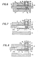
- a first mold supporting block 6 is fixed to the plate 4 and is so shaped to form an open cavity 6a to receive a mold plate 7, on the outer surface of which is engraved the profile of the outer surface of the female handle B of a handle pair A and B .
- the mold plate 7 is connected to the block 6 so as to can be easily removed and replaced by another mold plate carrying a different profile so as to enable to obtain handles of different designs.
- seats are also provided to receive two sliding wall members 8 and 9, associated with means adapted to move said wall members 8 and 9 to and from one another, as the two wings of a sliding door.
- the wall members 8 and 9 are retained and guided by longitudinal stringers 1( and 11 extending one towards the other.
- the means for causing the reciprocating movements of the wall members 8 and 9 in unison with the reciprocating movements of the two press members consists of a pair of horizontal rods 12 and 13 inclined outwardly and fixed to a second mold block 14 designed to be connected to the second of the press members, extending towards the molding chamber of the first mold block 6 and slidably passing through inclined holes 28 provided in the block 14.
- a cavity 14a facing the cavity 6a and designed to removably receive a mold plate 15, on the outer surface of which is engraved the profile of the outer surface of the handle A.
- a mold plate 15 on the outer surface of which is engraved the profile of the outer surface of the handle A.
- On the respective main surfaces of the wall members 8 and 9 are engraved profiles adapted to form the respective inner profiles of the handles B and A, when the wall members 8 and 9 are held with force in their contact positions ( Figure 5), so that said wall members 8 and 9, in their closure position, constitute the closure means of the two juxtaposed molding chambers and act also as countermolds for the mold 7 and 15, respectively.
- sets of coaxial holes 25, 25 b are arranged respectively through the plate 7, block 6 and the plate 4 as well as coaxial holes 25c, in the end portion of the wall members 8 and 9.
- Each set of holes 25, 25a, 25b, 25c is designed to receive a coaxial tubular stripper 19 connected to a common stripper control 19a.
- a punch 16 can slide up and down which is fixedly connected, at its outer end, to the plate 3, while its other end comprises a central recess 17 adapted to form a pin 1 in the male handle A, and an annular groove 18, spaced apart from this inner end, of such an extent to form the respective pin receiving hole 2 in the female handle B, as the molding unit is in its operative position, in which the stripper end edge positioned just-over the annular groove 18 serves to form an annular portion of the outer side of the handle B just about the hole 2.
- the injection of the plastic material ( Figure 9) is carried out through a tubular injection nozzle 20 passing through a hole 26 ( Figure 4) arranged in the plate 15, a coaxial hole 26a provided through the block 14, and two half-holes 26b provided at the facing edges of the wall members 8 and 9, said holes 26 to 26b having an axis positioned in the plane x-x and perpendicular to the wall members 7 and 8.
- the nozzle 20 has a closed inner 20a designed to come in contact with the outer surfaces of the mold plate 7.
- radial holes 21 are provided in the nozzle 20 to which short small tubes 22 are connected,which are designed to enter short holes 27 arranged in aligned positions in the facing edges of the wall members 8 and 9, said holes 27 communicating with pairs of transverse holes 23 which open in both the shaping surfaces of the wall members 8 and 9.
- the molding unit can be opened.
- the press members together with the mold block 6 and 14 carrying the molds 7 and 15 are moved away from each other separating the or each male handle A from the respective molding chambers.
- the wall members 8 and 9 are caused to move away from one another, owing to the presence of the inclined guiding bars 12 and 13.
- all the strippers 19 are caused to advance towards the handles A now suspended on the punches 16 by their pins 1 engaged into the seats 17 of the punches 16.
- each stripper 19 advances inside the molding chamber in which the handle B has been formed, it causes said handle B to come out from its molding chamber and the pin receiving hole 2 to be disengaged from the groove 1 8 .
- each punch 16 will be raised by a common punch control and, as a result thereof, the pin 1 comes out of the pin seat 17 and snap enters into the respective pin receiving hole 2 obtained in the handle B.
- each pair of handles A and B are extracted from their molding chambers and are assembled with one another. Said assembled handles A and B then fall out of the molding unit; thus a successive molding cycle can be carried out.
Landscapes
- Engineering & Computer Science (AREA)
- Manufacturing & Machinery (AREA)
- Mechanical Engineering (AREA)
- Making Paper Articles (AREA)
- Moulds For Moulding Plastics Or The Like (AREA)
- Lining Or Joining Of Plastics Or The Like (AREA)
Priority Applications (1)
| Application Number | Priority Date | Filing Date | Title |
|---|---|---|---|
| AT81830168T ATE10820T1 (de) | 1980-09-22 | 1981-09-18 | Verfahren und vorrichtung zum selbsttaetigen versehen eines kunststoffsackes mit einem paar handgriffe. |
Applications Claiming Priority (2)
| Application Number | Priority Date | Filing Date | Title |
|---|---|---|---|
| IT40076/80A IT1136334B (it) | 1980-09-22 | 1980-09-22 | Procedimento per stampaggio e assemblaggio contemporaneo dei manici per sporte in polietilene e simili,e stampo atto a realizzare tale procedimento |
| IT4007680 | 1980-09-22 |
Publications (3)
| Publication Number | Publication Date |
|---|---|
| EP0048702A2 true EP0048702A2 (de) | 1982-03-31 |
| EP0048702A3 EP0048702A3 (en) | 1983-03-02 |
| EP0048702B1 EP0048702B1 (de) | 1984-12-19 |
Family
ID=11247679
Family Applications (1)
| Application Number | Title | Priority Date | Filing Date |
|---|---|---|---|
| EP81830168A Expired EP0048702B1 (de) | 1980-09-22 | 1981-09-18 | Verfahren und Vorrichtung zum selbsttätigen Versehen eines Kunststoffsackes mit einem Paar Handgriffe |
Country Status (5)
| Country | Link |
|---|---|
| EP (1) | EP0048702B1 (de) |
| JP (1) | JPS5787342A (de) |
| AT (1) | ATE10820T1 (de) |
| DE (1) | DE3167850D1 (de) |
| IT (1) | IT1136334B (de) |
Cited By (1)
| Publication number | Priority date | Publication date | Assignee | Title |
|---|---|---|---|---|
| EP0155436A1 (de) * | 1984-02-20 | 1985-09-25 | Aldo Gussoni | Vorrichtung zur Herstellung von Handgriffen aus Kunststoff für kleine Taschen |
Family Cites Families (7)
| Publication number | Priority date | Publication date | Assignee | Title |
|---|---|---|---|---|
| DE1163527B (de) * | 1957-10-08 | 1964-02-20 | Plax G M B H Deutsche | Verfahren zur Herstellung einer aus thermoplastischem Kunststoff bestehenden Verschlusskappe |
| US3362302A (en) * | 1965-08-12 | 1968-01-09 | Studley Paper Company Inc | Bag closure |
| US3373460A (en) * | 1965-09-13 | 1968-03-19 | Michael Ladney Jr. | Molding apparatus |
| US3461488A (en) * | 1966-04-08 | 1969-08-19 | Rexall Drug Chemical | Mold ejection assemblable two-piece cap |
| US3647338A (en) * | 1969-09-15 | 1972-03-07 | Nippon Columbia | Disc record injection molding machine |
| US4012827A (en) * | 1975-06-09 | 1977-03-22 | Gilbert Lawrence Abrams | Method for molding composite articles |
| DE2528903C3 (de) * | 1975-06-28 | 1979-03-01 | F. & G. Hachtel, 7080 Aalen | Verfahren, spritzgegossener Rollring und Spritzgießform zur Herstellung eines Rollringes für Gardinenschienen |
-
1980
- 1980-09-22 IT IT40076/80A patent/IT1136334B/it active
-
1981
- 1981-09-18 EP EP81830168A patent/EP0048702B1/de not_active Expired
- 1981-09-18 DE DE8181830168T patent/DE3167850D1/de not_active Expired
- 1981-09-18 AT AT81830168T patent/ATE10820T1/de not_active IP Right Cessation
- 1981-09-22 JP JP56150518A patent/JPS5787342A/ja active Pending
Cited By (1)
| Publication number | Priority date | Publication date | Assignee | Title |
|---|---|---|---|---|
| EP0155436A1 (de) * | 1984-02-20 | 1985-09-25 | Aldo Gussoni | Vorrichtung zur Herstellung von Handgriffen aus Kunststoff für kleine Taschen |
Also Published As
| Publication number | Publication date |
|---|---|
| ATE10820T1 (de) | 1985-01-15 |
| IT8040076A0 (it) | 1980-09-22 |
| EP0048702A3 (en) | 1983-03-02 |
| EP0048702B1 (de) | 1984-12-19 |
| DE3167850D1 (en) | 1985-01-31 |
| IT1136334B (it) | 1986-08-27 |
| JPS5787342A (en) | 1982-05-31 |
Similar Documents
| Publication | Publication Date | Title |
|---|---|---|
| CN108672633B (zh) | 自动冲压模具 | |
| US4432127A (en) | Process of molding and assembling a pair of handles of a plastic bag | |
| JPH11512355A (ja) | 移動分離補助部材を有する再構成可能な成形型 | |
| US4074413A (en) | Method and apparatus for manufacturing separable sliding clasp fasteners | |
| CN105903816A (zh) | 一种可实现管件自动脱模的冲压整形系统 | |
| DE2613689A1 (de) | Verfahren und vorrichtung zum herstellen von behaeltern aus thermoplastischen kunststoffen | |
| US3978186A (en) | Method for making a partitioned container | |
| US3977821A (en) | Apparatus for making a partitioned container | |
| EP0048702B1 (de) | Verfahren und Vorrichtung zum selbsttätigen Versehen eines Kunststoffsackes mit einem Paar Handgriffe | |
| DE3443715A1 (de) | Vorrichtung zum herstellen eines ein ansetzteil aufweisenden hohlkoerpers | |
| IT8667862A1 (it) | Pressa perfezionata per lo stampaggio di manufatti di materiale polimerico termoplastico termoindurente poliuretanico e suo procedimento di conduzione | |
| CA1184721A (en) | Process of and apparatus for automatically providing a pair of handles of a plastic bag | |
| CA1149118A (en) | Plastic injection molding machine | |
| DE2317456C2 (de) | Verfahren zur Herstellung eines Luftreifens | |
| CN210336745U (zh) | 一种用于模具的型腔隧道滑块抽芯机构 | |
| EP0018044B1 (de) | Verfahren und Vorrichtung zum Spritzgiessen hohler Kunststoffgegenstände | |
| CN218395612U (zh) | 一种汽车左右后轮罩冲压模具 | |
| US5207966A (en) | Method for molding a strip of blind rivets | |
| US5238377A (en) | Apparatus for making blind rivets | |
| DE3226841C2 (de) | Vorrichtung zum Thermoformen von Behältern aus einer Folienbahn aus thermoplastischem Kunststoff | |
| CN110181723B (zh) | 适用于橡胶复合产品的模具及其使用方法 | |
| US4129639A (en) | Method and apparatus for manufacturing open end sliding clasp fasteners | |
| CN209320217U (zh) | 一种双色注塑模的三级顶出机构 | |
| DE2248671A1 (de) | Vorrichtung und verfahren zum formpressen | |
| CN219311871U (zh) | 一种模芯结构及具有其的注塑系统 |
Legal Events
| Date | Code | Title | Description |
|---|---|---|---|
| PUAI | Public reference made under article 153(3) epc to a published international application that has entered the european phase |
Free format text: ORIGINAL CODE: 0009012 |
|
| AK | Designated contracting states |
Designated state(s): AT BE CH DE FR GB LU NL SE |
|
| PUAL | Search report despatched |
Free format text: ORIGINAL CODE: 0009013 |
|
| AK | Designated contracting states |
Designated state(s): AT BE CH DE FR GB LI LU NL SE |
|
| 17P | Request for examination filed |
Effective date: 19830422 |
|
| GRAA | (expected) grant |
Free format text: ORIGINAL CODE: 0009210 |
|
| AK | Designated contracting states |
Designated state(s): AT BE CH DE FR GB LI LU NL SE |
|
| PG25 | Lapsed in a contracting state [announced via postgrant information from national office to epo] |
Ref country code: SE Effective date: 19841219 Ref country code: LI Effective date: 19841219 Ref country code: CH Effective date: 19841219 Ref country code: AT Effective date: 19841219 |
|
| REF | Corresponds to: |
Ref document number: 10820 Country of ref document: AT Date of ref document: 19850115 Kind code of ref document: T |
|
| REF | Corresponds to: |
Ref document number: 3167850 Country of ref document: DE Date of ref document: 19850131 |
|
| REG | Reference to a national code |
Ref country code: CH Ref legal event code: PL |
|
| ET | Fr: translation filed | ||
| PG25 | Lapsed in a contracting state [announced via postgrant information from national office to epo] |
Ref country code: LU Free format text: LAPSE BECAUSE OF NON-PAYMENT OF DUE FEES Effective date: 19850930 |
|
| PLBE | No opposition filed within time limit |
Free format text: ORIGINAL CODE: 0009261 |
|
| STAA | Information on the status of an ep patent application or granted ep patent |
Free format text: STATUS: NO OPPOSITION FILED WITHIN TIME LIMIT |
|
| 26N | No opposition filed | ||
| PGFP | Annual fee paid to national office [announced via postgrant information from national office to epo] |
Ref country code: NL Payment date: 19860930 Year of fee payment: 6 |
|
| PG25 | Lapsed in a contracting state [announced via postgrant information from national office to epo] |
Ref country code: BE Effective date: 19870930 |
|
| BERE | Be: lapsed |
Owner name: DIAZZI MAURO Effective date: 19870930 |
|
| PG25 | Lapsed in a contracting state [announced via postgrant information from national office to epo] |
Ref country code: NL Effective date: 19880401 |
|
| NLV4 | Nl: lapsed or anulled due to non-payment of the annual fee | ||
| PG25 | Lapsed in a contracting state [announced via postgrant information from national office to epo] |
Ref country code: FR Free format text: LAPSE BECAUSE OF NON-PAYMENT OF DUE FEES Effective date: 19880531 |
|
| PG25 | Lapsed in a contracting state [announced via postgrant information from national office to epo] |
Ref country code: DE Effective date: 19880601 |
|
| GBPC | Gb: european patent ceased through non-payment of renewal fee | ||
| REG | Reference to a national code |
Ref country code: FR Ref legal event code: ST |
|
| PG25 | Lapsed in a contracting state [announced via postgrant information from national office to epo] |
Ref country code: GB Free format text: LAPSE BECAUSE OF NON-PAYMENT OF DUE FEES Effective date: 19881118 |