EP0049054A2 - Dispositif pour la pyrolyse de pneumatiques fragmentés - Google Patents
Dispositif pour la pyrolyse de pneumatiques fragmentés Download PDFInfo
- Publication number
- EP0049054A2 EP0049054A2 EP81304022A EP81304022A EP0049054A2 EP 0049054 A2 EP0049054 A2 EP 0049054A2 EP 81304022 A EP81304022 A EP 81304022A EP 81304022 A EP81304022 A EP 81304022A EP 0049054 A2 EP0049054 A2 EP 0049054A2
- Authority
- EP
- European Patent Office
- Prior art keywords
- oven
- tires
- container
- hot air
- heating
- Prior art date
- Legal status (The legal status is an assumption and is not a legal conclusion. Google has not performed a legal analysis and makes no representation as to the accuracy of the status listed.)
- Withdrawn
Links
Images



Classifications
-
- B—PERFORMING OPERATIONS; TRANSPORTING
- B29—WORKING OF PLASTICS; WORKING OF SUBSTANCES IN A PLASTIC STATE IN GENERAL
- B29B—PREPARATION OR PRETREATMENT OF THE MATERIAL TO BE SHAPED; MAKING GRANULES OR PREFORMS; RECOVERY OF PLASTICS OR OTHER CONSTITUENTS OF WASTE MATERIAL CONTAINING PLASTICS
- B29B17/00—Recovery of plastics or other constituents of waste material containing plastics
- B29B17/04—Disintegrating plastics, e.g. by milling
-
- C—CHEMISTRY; METALLURGY
- C10—PETROLEUM, GAS OR COKE INDUSTRIES; TECHNICAL GASES CONTAINING CARBON MONOXIDE; FUELS; LUBRICANTS; PEAT
- C10B—DESTRUCTIVE DISTILLATION OF CARBONACEOUS MATERIALS FOR PRODUCTION OF GAS, COKE, TAR, OR SIMILAR MATERIALS
- C10B53/00—Destructive distillation, specially adapted for particular solid raw materials or solid raw materials in special form
- C10B53/07—Destructive distillation, specially adapted for particular solid raw materials or solid raw materials in special form of solid raw materials consisting of synthetic polymeric materials, e.g. tyres
-
- C—CHEMISTRY; METALLURGY
- C10—PETROLEUM, GAS OR COKE INDUSTRIES; TECHNICAL GASES CONTAINING CARBON MONOXIDE; FUELS; LUBRICANTS; PEAT
- C10B—DESTRUCTIVE DISTILLATION OF CARBONACEOUS MATERIALS FOR PRODUCTION OF GAS, COKE, TAR, OR SIMILAR MATERIALS
- C10B7/00—Coke ovens with mechanical conveying means for the raw material inside the oven
- C10B7/14—Coke ovens with mechanical conveying means for the raw material inside the oven with trucks, containers, or trays
-
- B—PERFORMING OPERATIONS; TRANSPORTING
- B29—WORKING OF PLASTICS; WORKING OF SUBSTANCES IN A PLASTIC STATE IN GENERAL
- B29B—PREPARATION OR PRETREATMENT OF THE MATERIAL TO BE SHAPED; MAKING GRANULES OR PREFORMS; RECOVERY OF PLASTICS OR OTHER CONSTITUENTS OF WASTE MATERIAL CONTAINING PLASTICS
- B29B17/00—Recovery of plastics or other constituents of waste material containing plastics
- B29B17/04—Disintegrating plastics, e.g. by milling
- B29B2017/0424—Specific disintegrating techniques; devices therefor
- B29B2017/0496—Pyrolysing the materials
-
- B—PERFORMING OPERATIONS; TRANSPORTING
- B29—WORKING OF PLASTICS; WORKING OF SUBSTANCES IN A PLASTIC STATE IN GENERAL
- B29L—INDEXING SCHEME ASSOCIATED WITH SUBCLASS B29C, RELATING TO PARTICULAR ARTICLES
- B29L2030/00—Pneumatic or solid tyres or parts thereof
-
- Y—GENERAL TAGGING OF NEW TECHNOLOGICAL DEVELOPMENTS; GENERAL TAGGING OF CROSS-SECTIONAL TECHNOLOGIES SPANNING OVER SEVERAL SECTIONS OF THE IPC; TECHNICAL SUBJECTS COVERED BY FORMER USPC CROSS-REFERENCE ART COLLECTIONS [XRACs] AND DIGESTS
- Y02—TECHNOLOGIES OR APPLICATIONS FOR MITIGATION OR ADAPTATION AGAINST CLIMATE CHANGE
- Y02P—CLIMATE CHANGE MITIGATION TECHNOLOGIES IN THE PRODUCTION OR PROCESSING OF GOODS
- Y02P20/00—Technologies relating to chemical industry
- Y02P20/141—Feedstock
- Y02P20/143—Feedstock the feedstock being recycled material, e.g. plastics
-
- Y—GENERAL TAGGING OF NEW TECHNOLOGICAL DEVELOPMENTS; GENERAL TAGGING OF CROSS-SECTIONAL TECHNOLOGIES SPANNING OVER SEVERAL SECTIONS OF THE IPC; TECHNICAL SUBJECTS COVERED BY FORMER USPC CROSS-REFERENCE ART COLLECTIONS [XRACs] AND DIGESTS
- Y02—TECHNOLOGIES OR APPLICATIONS FOR MITIGATION OR ADAPTATION AGAINST CLIMATE CHANGE
- Y02P—CLIMATE CHANGE MITIGATION TECHNOLOGIES IN THE PRODUCTION OR PROCESSING OF GOODS
- Y02P70/00—Climate change mitigation technologies in the production process for final industrial or consumer products
- Y02P70/10—Greenhouse gas [GHG] capture, material saving, heat recovery or other energy efficient measures, e.g. motor control, characterised by manufacturing processes, e.g. for rolling metal or metal working
-
- Y—GENERAL TAGGING OF NEW TECHNOLOGICAL DEVELOPMENTS; GENERAL TAGGING OF CROSS-SECTIONAL TECHNOLOGIES SPANNING OVER SEVERAL SECTIONS OF THE IPC; TECHNICAL SUBJECTS COVERED BY FORMER USPC CROSS-REFERENCE ART COLLECTIONS [XRACs] AND DIGESTS
- Y02—TECHNOLOGIES OR APPLICATIONS FOR MITIGATION OR ADAPTATION AGAINST CLIMATE CHANGE
- Y02W—CLIMATE CHANGE MITIGATION TECHNOLOGIES RELATED TO WASTEWATER TREATMENT OR WASTE MANAGEMENT
- Y02W30/00—Technologies for solid waste management
- Y02W30/50—Reuse, recycling or recovery technologies
- Y02W30/62—Plastics recycling; Rubber recycling
Definitions
- the present invention provides for the recovery of the basic components which make up a tire through a unique pyrolysis process.
- the basic components of a tire which are recoverable with this process include oil and ammonia and the gases methane, butane and propane as well as carbon and steel.
- the process involves the steps of shredding tires to a predetermined size, filling pyrolytic containers with the shredded tires, placing the pyrolytic container inside a closed oven, purging the oven of oxygen, heating the oven to a temperature sufficient to evaporate the gasous components of a tire, condensing the vapor to liquify the oil and ammonia, and storing the uncondensed gases such as methane, butane and propane.
- the oven is again purged of gases and the pyrolytic container is then removed from the oven to recover the carbon and steel.
- a unique oven has been designed for pyrolyzing the tires.
- This oven includes a plurality of hot air conduits which encircle the pyrolytic container to provide an even distribution of heat about the container.
- a novel roof configuration is built into the furnace to create a vapor collection zone where the heated gases from the tires collect.
- the containers or bins which are used to transport the shredded tires into the oven are specially designed for compatibility with the oven configuration.
- the containers are completely enclosed on all sides except the front end which is open to allow the gases to escape and provide access to the bin.
- the top of the container has an inclined configuration which conforms to the configuration of the oven so that gases created within the container will flow toward the gas collection zone provided in the oven.
- the enclosed portion of the container is immersed in water when removed from the oven to allow for rapid cooling of the carbon to prevent ignition on exposure of the carbon to the atmosphere.
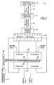
- the tires Feeding the tires by means of a conveyor 12 to a shredder 14.
- the tires are shredded by means of a shredder of the type shown in my earlier U.S. Letters Patent nos. 4,205,799.
- the shredding step is essential to the success of the system in that the tires must be shredded to a predetermined size, approximately three inches by three inches, which can be reclaimed as described hereinafter:
- a complete system includes four individual ovens 22. This is necessary to obtain sufficient efficiency to operate on a competitive basis as described below.
- a tire weighing an average of 25 pounds contains the following approximate amounts of recoverable materials: 1.8 gallons of fuel oil; 7.8 pounds of carbon; 1.7 pounds of propane methane butane gases; 1 pound of steel and .084 gallons of ammonia.
- Using a system including four furnaces as contemplated herein approximately 3,000 tires can be processed per day. This will produce 5,400 gallons of number 2 fuel oil; 23,400 pounds of carbon; 5,250 pounds of propane, methane, or butane; 3,000 pounds of steel and 250 gallons of ammonia.
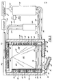
- Each of the ovens 22 is identical in configuration and independently operated as seen in Figure 3 and 4.
- Each oven includes a housing having a bottom wall 26, side walls 28, a back wall 30 and a.top wall 32 which define a primary heating zone.
- the front of the housing is open and is closed by means of a pair of doors 34 supported on swing arms 36.
- the swing arms are pivotally connected to the doors 34 by pins 38 and pivotally connected to the end walls 28 by pins 40.
- Each of the walls is of conventional oven construction having a insulating medium 42 in each of the walls and doors. The medium is capable of withstanding temperatures up to 1200° F or more.
- a pair of tracks 44 are supported in the bottom wall 26 by means of steel I beams 46.
- the oven is heated by hot air by means of a plurality of hot air conduits or pipes 48 and 50 which are alternately, spirally supported around the inside surface of the side walls, back wall and bottom wall to completely surround the primary heating zone.
- the hot air is forced through the conduits by means of a forced draft fan 52 through a heat exchanger 54 and into a combustor 56 through pipes 58.
- the air is heated to a temperature in excess of 1200° F in the combustor 56 and is forced into the pipes 48 and 50 through pipes 60 and 62.
- the air is returned to the heat exchanger from the oven through pipes 64 and 66. Approximately 1/3 of the exhaust air is vented to atmosphere through a vent pipe 68 and the remaining 2/3 is recirculated to the combustor.
- the combustor is a conventional gas fired combustor and can be fired either by means of natural gas or by means of the uncondensed gases collected from the condensers 25 as described hereinafter.
- the heat exchanger is also of a conventional type and can be adjusted to increase or decrease the recirculated air. Heat exchangers of the type commonly referred to as energy wheel, metal surface or heat pipe can be used. A metal surface type distributed by Engineered Products Inc. of Boise, Idaho, is presently being used.
- Vapors produced in the pryolyzer oven 22 are directed to an outlet pipe 70 which is connected to one or more condensers 25 to liquify the discharged oil and ammonia vapors.
- the uncondensed gases, methane, propane, and butane can be collected for subsequent use in firing the combustor 56.
- Means are provided for directing the vapors in the oven to the outlet pipe 70.
- Such means is in the form of a tapered or inclined top wall 32.
- the top wall 32 is formed from three triangular sections 72, 74 and 76.
- the three sections 72, 74 and 76 are connected to form an apex 78 at the high portion of the oven to form a collection zone at the top of the oven for the vapors and/or gases.
- the walls 72, 74 and 76 thus form an inclined path of travel for the vapors and gases to the pipe 70.
- Means are provided in the top wall 32 of the oven for purging the oven both before the pyrolysis cycle is started and after the pyrolysis cycle has been completed.
- Such means is in the form of pipes 80 and 82 located at each end of the oven.
- Inert gases such as carbon dioxide or nitrogen which are both heavier than air, are admitted through pipe 82, and the air present is exhausted through pipe 80.
- Appropriate valves are provided in the pipes 70, 80 and 82 to control the discharge of air and gases from the oven in the proper sequence. The normal sequence for purging is to close the outlet valve pipe 70 and to admit the inert gases through pipe 82 and exhaust any air present through pipe 80.
- valves in pipes 80 and 82 are closed and the valve in pipe 70 opened.
- the valve in pipe 70 is closed and the valve in pipe 80 and 82 are opened.
- Inert gas is admitted through pipe 82 to exhaust the residual vapors present through pipe 80.
- Each tote bin as seen in Figures 5 and 6 includes a floor or base 86, side walls 88, a rear wall 90 and a top wall 92.
- the top wall 92 is made up of three sections 92A, 92B and 92C which form an inclined or tapered path of travel for the vapors similar to the top wall 32 of the oven.
- the sections 92A, 92B and 92C having their apex at the forward end of the container to form an inclined surface for the gases and vapors evaporated from the shredded rubber during the heating process.
- the front of the tote bin is closed by means of a pair of panels or doors 94 which are pivotally connected to the side walls 88 at 96.
- the doors are provided with a plurality of openings 98 to allow for the free flow of gases or vapor through the open end of the tote bin.
- a solid plate 100 extends upward a short distance from the base across the open end of the tote bin to form a wall to prevent liquid rubber from flowing out of the tote bin during the pyrolysis process.
- the tote bin is moved into and out of the oven on wheels 102 which ride on the tracks 44 located in the oven.
- the tote bin 84 is shown in a position to be moved into one of the ovens 22.
- the tote bin is supported by means of a collapsible track assembly 104.
- the track assembly includes a pair of rails 106 which are supported on links 108 that are pivotally connected to the rails 106 and the base 110.
- links 108 that are pivotally connected to the rails 106 and the base 110.
- the rails 106 are moved rearward and pivoted downward on links 108 to clear the space outside the doors.
- the rails 106 are moved forward and pivoted upwardly on the links 108 into abutting engagement with the ends of the rails 44 in the oven.
- the tote bin 84 can then be rolled on the rails 106 and into the oven on rails 44.
- Means can be provided for automatically moving the tote bin into the oven.
- Such means can be in the form of a hydraulic pusher assembly which engages the rear of the tote bin to push it into the oven.
- the hydraulic assembly can also be used to pull the tote bin from the oven.
- the doors are closed and the oven purged of oxygen by opening exhaust pipe 80 and admitting inert gas into the oven through pipe 82.
- the pipes 80 and 82 are then closed and the outlet valve in the pipe 70 opened.
- the vapors created on vaporization of the oil and ammonia, and the gases, propane, methane and butane which are contained in the shredded tire flow out through the tube 70 into the condensers 25.
- the vapor is condensed in a conventional manner to remove the oil and ammonia and the remaining propane, methane and butane collected for use as a source of fuel for the hot air furnace or collected or stored for later use.
- the tote bins are designed to carry approximately 2,600 pounds of shredded tires which is a little more than a 100 tires having an approximate weight of 25 pounds.
- the tote bins are removed from the oven with the carbon residue and steel remaining in the bins. Since the tires were shredded into strips of approximately three by three inches, the steel strips are small enough to be removable by magnetic means.
- the carbon residue will be at an elevated temperature and will start to burn or smolder on exposure to air.
- the bin is cooled immediately by immersion of the bin into water. Since the bin is closed on all sides except the front, the carbon will be cooled without getting wet.
- the carbon residue and steel wire are removed from the bin and crushed by means of a pair of roll crushers. The steel strips can then be removed by magnets.
Landscapes
- Chemical & Material Sciences (AREA)
- Engineering & Computer Science (AREA)
- Oil, Petroleum & Natural Gas (AREA)
- Materials Engineering (AREA)
- Organic Chemistry (AREA)
- Environmental & Geological Engineering (AREA)
- Mechanical Engineering (AREA)
- Separation, Recovery Or Treatment Of Waste Materials Containing Plastics (AREA)
- Production Of Liquid Hydrocarbon Mixture For Refining Petroleum (AREA)
- Processing Of Solid Wastes (AREA)
- Manufacture Of Porous Articles, And Recovery And Treatment Of Waste Products (AREA)
Applications Claiming Priority (2)
| Application Number | Priority Date | Filing Date | Title |
|---|---|---|---|
| US19117180A | 1980-09-26 | 1980-09-26 | |
| US191171 | 1980-09-26 |
Publications (2)
| Publication Number | Publication Date |
|---|---|
| EP0049054A2 true EP0049054A2 (fr) | 1982-04-07 |
| EP0049054A3 EP0049054A3 (fr) | 1982-09-08 |
Family
ID=22704403
Family Applications (1)
| Application Number | Title | Priority Date | Filing Date |
|---|---|---|---|
| EP19810304022 Withdrawn EP0049054A3 (fr) | 1980-09-26 | 1981-09-02 | Dispositif pour la pyrolyse de pneumatiques fragmentés |
Country Status (4)
| Country | Link |
|---|---|
| EP (1) | EP0049054A3 (fr) |
| JP (1) | JPS57123287A (fr) |
| BR (1) | BR8106138A (fr) |
| CA (1) | CA1166593A (fr) |
Cited By (6)
| Publication number | Priority date | Publication date | Assignee | Title |
|---|---|---|---|---|
| WO1996036472A1 (fr) * | 1995-05-15 | 1996-11-21 | 'robentec' Company Limited | Procede de recyclage de dechets caoutchouteux |
| EP0853114A3 (fr) * | 1997-01-10 | 1998-09-09 | Richard Bouziane | Procédé discontinu pour le recyclage de déchets contenant des hydrocarbures |
| WO2004094561A1 (fr) * | 2003-04-23 | 2004-11-04 | Tyre Reduction Services (Pty) Ltd | Systeme de reduction de pneus usages |
| ES2335567A1 (es) * | 2009-03-25 | 2010-03-29 | Jesus Tomas Ruiz Rueda (20%) | Sistema de reciclaje polivalente de neumaticos y otros residuos industriales. |
| CN109822776A (zh) * | 2019-02-18 | 2019-05-31 | 哈尔滨博实自动化股份有限公司 | 低分子液体橡胶制备装置 |
| WO2024069572A1 (fr) | 2022-09-30 | 2024-04-04 | Tyre Recycling Solutions Sa | Appareil de conversion thermochimique d'un échantillon comprenant du caoutchouc ou d'un échantillon provenant de pneus |
Families Citing this family (1)
| Publication number | Priority date | Publication date | Assignee | Title |
|---|---|---|---|---|
| JP5853116B1 (ja) * | 2015-06-10 | 2016-02-09 | 嘉弘 月村 | 有機質廃棄物熱分解炉、同熱分解装置 |
Family Cites Families (4)
| Publication number | Priority date | Publication date | Assignee | Title |
|---|---|---|---|---|
| US1898326A (en) * | 1932-04-16 | 1933-02-21 | Oscar W Wahlstrom | Process of destructive distillation and carbonization of waste matter |
| DE747862C (de) * | 1935-06-03 | 1944-10-02 | Igor Soubbotin | Kanalofen zum Schwelen von Schiefer, Braunkohlen, Steinkohlen, Torf und aehnlichen Stoffen |
| US3525673A (en) * | 1969-03-24 | 1970-08-25 | Eric C Cameron | Closed,controlled system for carbonizing organic refuse |
| FR2385037A1 (fr) * | 1977-03-24 | 1978-10-20 | Lembourg Ghislain | Procede de traitement thermique de dechets et four pour sa mise en oeuvre |
-
1981
- 1981-08-25 CA CA000384572A patent/CA1166593A/fr not_active Expired
- 1981-09-02 EP EP19810304022 patent/EP0049054A3/fr not_active Withdrawn
- 1981-09-24 BR BR8106138A patent/BR8106138A/pt unknown
- 1981-09-26 JP JP15284581A patent/JPS57123287A/ja active Pending
Cited By (8)
| Publication number | Priority date | Publication date | Assignee | Title |
|---|---|---|---|---|
| WO1996036472A1 (fr) * | 1995-05-15 | 1996-11-21 | 'robentec' Company Limited | Procede de recyclage de dechets caoutchouteux |
| EP0853114A3 (fr) * | 1997-01-10 | 1998-09-09 | Richard Bouziane | Procédé discontinu pour le recyclage de déchets contenant des hydrocarbures |
| WO2004094561A1 (fr) * | 2003-04-23 | 2004-11-04 | Tyre Reduction Services (Pty) Ltd | Systeme de reduction de pneus usages |
| ES2335567A1 (es) * | 2009-03-25 | 2010-03-29 | Jesus Tomas Ruiz Rueda (20%) | Sistema de reciclaje polivalente de neumaticos y otros residuos industriales. |
| WO2010109047A1 (fr) * | 2009-03-25 | 2010-09-30 | RUIZ RUEDA, Jesús Tomás | Système de recyclage polyvalent de pneumatiques et autres résidus industriels |
| ES2335567B1 (es) * | 2009-03-25 | 2011-02-02 | Jesus Tomas Ruiz Rueda (20%) | Sistema de reciclaje polivalente de neumaticos y otros residuos industriales. |
| CN109822776A (zh) * | 2019-02-18 | 2019-05-31 | 哈尔滨博实自动化股份有限公司 | 低分子液体橡胶制备装置 |
| WO2024069572A1 (fr) | 2022-09-30 | 2024-04-04 | Tyre Recycling Solutions Sa | Appareil de conversion thermochimique d'un échantillon comprenant du caoutchouc ou d'un échantillon provenant de pneus |
Also Published As
| Publication number | Publication date |
|---|---|
| JPS57123287A (en) | 1982-07-31 |
| CA1166593A (fr) | 1984-05-01 |
| EP0049054A3 (fr) | 1982-09-08 |
| BR8106138A (pt) | 1982-06-15 |
Similar Documents
| Publication | Publication Date | Title |
|---|---|---|
| US4401513A (en) | Apparatus for pyrolyzing shredded tires | |
| US5167772A (en) | Apparatus for pyrolysis of tires and waste | |
| CA1200106A (fr) | Separation des metaux contenus dans les rebuts d'accumulateurs au nickel-cadmium epuises | |
| EP1163092B1 (fr) | Processus de pyrolyse permettant de recuperer des matieres souhaitables de pneus de vehicules | |
| JP7017860B2 (ja) | 廃リチウムイオン電池の処理方法 | |
| US8409406B2 (en) | Recycling of tires, rubber and other organic material through vapor distillation | |
| JP6716389B2 (ja) | 廃リチウムイオン電池からの有価物の回収方法及びデータベースの作成方法 | |
| US11996528B2 (en) | Method to open up electro chemical energy storage devices and thermal treatment system | |
| EP1522355B1 (fr) | Procede, systeme et conteneur pour recycler des ressources | |
| US20090200150A1 (en) | Waste-tire recycling system | |
| EP0049054A2 (fr) | Dispositif pour la pyrolyse de pneumatiques fragmentés | |
| WO1994002780A1 (fr) | Appareil permettant des variations thermiques dans les dimensions de pieces metalliques dans un mecanisme de distillation en cornue | |
| CA1242406A (fr) | Methode et dispositif de distillation destructive des dechets et ordures urbaines, avec derivation d'un sous-produit et d'energie | |
| JP7179559B2 (ja) | 廃リチウムイオン電池の処理装置及び処理方法 | |
| JP7174652B2 (ja) | 廃リチウムイオン電池の処理装置 | |
| GB2303859A (en) | Tyre pyrolysis method and apparatus | |
| CZ304835B6 (cs) | Způsob výroby paliv pro energetiku a zařízení pro výrobu paliv | |
| WO1994002060A1 (fr) | Appareil de distillation en cornue de substances organiques | |
| RU2291168C1 (ru) | Способ переработки резиносодержащих отходов и установка для его осуществления (варианты) | |
| US9120977B1 (en) | Recycling of tires, rubber and other organic material through vapor distillation | |
| JPH11246917A (ja) | 乾留式金属回収方法及び装置 | |
| EP0670983B1 (fr) | Procede de distillation en cornue de substances organiques | |
| JPH08510011A (ja) | 固体製造物からの液体部分の連続的な分離と回収と固体製造物の熱分解真空処理方法及び装置 | |
| KR20090106951A (ko) | 열분해 방식을 채용한 폐타이어에서 오일을 추출하는 방법 | |
| KR20010042978A (ko) | 유리 산소 함량이 낮은 연무를 이용한 쓰레기의 열분해처리 장치 |
Legal Events
| Date | Code | Title | Description |
|---|---|---|---|
| PUAI | Public reference made under article 153(3) epc to a published international application that has entered the european phase |
Free format text: ORIGINAL CODE: 0009012 |
|
| AK | Designated contracting states |
Designated state(s): AT BE CH DE FR GB IT LU NL SE |
|
| PUAL | Search report despatched |
Free format text: ORIGINAL CODE: 0009013 |
|
| AK | Designated contracting states |
Designated state(s): AT BE CH DE FR GB IT LU NL SE |
|
| STAA | Information on the status of an ep patent application or granted ep patent |
Free format text: STATUS: THE APPLICATION IS DEEMED TO BE WITHDRAWN |
|
| 18D | Application deemed to be withdrawn |
Effective date: 19830815 |