EP0049148B1 - Verfahren zum Vermeiden von Schäden an einer Eintauchdüse eines Ofens zum Entkohlen von Stahl bei der Stahlherstellung - Google Patents
Verfahren zum Vermeiden von Schäden an einer Eintauchdüse eines Ofens zum Entkohlen von Stahl bei der Stahlherstellung Download PDFInfo
- Publication number
- EP0049148B1 EP0049148B1 EP81304470A EP81304470A EP0049148B1 EP 0049148 B1 EP0049148 B1 EP 0049148B1 EP 81304470 A EP81304470 A EP 81304470A EP 81304470 A EP81304470 A EP 81304470A EP 0049148 B1 EP0049148 B1 EP 0049148B1
- Authority
- EP
- European Patent Office
- Prior art keywords
- gas
- tuyere
- particulate material
- blown
- refining
- Prior art date
- Legal status (The legal status is an assumption and is not a legal conclusion. Google has not performed a legal analysis and makes no representation as to the accuracy of the status listed.)
- Expired
Links
Images


Classifications
-
- C—CHEMISTRY; METALLURGY
- C21—METALLURGY OF IRON
- C21C—PROCESSING OF PIG-IRON, e.g. REFINING, MANUFACTURE OF WROUGHT-IRON OR STEEL; TREATMENT IN MOLTEN STATE OF FERROUS ALLOYS
- C21C5/00—Manufacture of carbon-steel, e.g. plain mild steel, medium carbon steel or cast steel or stainless steel
- C21C5/28—Manufacture of steel in the converter
- C21C5/30—Regulating or controlling the blowing
- C21C5/35—Blowing from above and through the bath
-
- C—CHEMISTRY; METALLURGY
- C21—METALLURGY OF IRON
- C21C—PROCESSING OF PIG-IRON, e.g. REFINING, MANUFACTURE OF WROUGHT-IRON OR STEEL; TREATMENT IN MOLTEN STATE OF FERROUS ALLOYS
- C21C5/00—Manufacture of carbon-steel, e.g. plain mild steel, medium carbon steel or cast steel or stainless steel
- C21C5/28—Manufacture of steel in the converter
- C21C5/30—Regulating or controlling the blowing
- C21C5/34—Blowing through the bath
Definitions
- the present invention relates to a method of preventing damage of an immersed tuyere of a decarburizing furnace or a converter for use in an oxygen steel making process. More specifically, the invention is concerned with a method of preventing the damage to an immersed tuyere often experienced in the oxygen steel making process in which molten pig iron is decarburized and refined into steel.
- pure oxygen gas is blown as a jet having high energy to provide a driving force for an oxidizing reaction by vigorously reacting with C, Si and Mn in the molten pig iron.
- the decarburization reaction is enhanced by the stirring action of the CO gas generated as a result of reaction of oxygen with C and by the stirring action of the jet flow of oxygen from the lance, to permit an approximately eight-fold increase of the steel making efficiency as compared with the conventional process using an open hearth.
- This new process makes it possible to produce steel materials of higher quality at a higher rate that the conventional open hearth steel making process.
- the top blown oxygen steel making process although it offers the above-described various advantages, still suffers the following problem. Namely, as the end of the decarburization refining approaches, the carbon content in the molten metal is successively lowered and reduces the rate of generation of CO as the product of reaction with oxygen in the molten metal. As a result of this the stirring effect of the.CO on the molten metal bath and slag is also reduced undesirably to lower the decarburization efficiency of the oxygen thus causing the oxidation of iron to proceed beyond the equilibrium value, which in turn makes the subsequent dephosphorization difficult to perform.
- the U.S. Steel Company has developed a so-called Q-BOP method which is an improvement of the OBM method that makes the latter suitable for low phosphor blowing.
- This Q-BOP method makes use of the advantage inherent in the bottom blown steel converter process over the top blown oxygen steel making process, and is now making rapid progress.
- the Q-BOP method is not free from the problem of the damage of the furnace bottom peculiar to the bottom blow converter, and consumes a large amount of refractory material.
- the use of hydrocarbon gas as the tuyere coolant inconveniently increases [H] in the molten steel due to the decomposition of the gas and gives rise to defects in the steel produced. It is possible to use N 2 gas in place of or in addition to the hydrocarbon gas.
- the British Patent Specification No. 820357 proposes a dephosphorization refining process in which lime or other basic oxides and/or a dephosphorizing agent such as fluorite are blown into a furnace from the bottom of the furnace together with an oxidizing carrier gas.
- Japanese Patent Publication No. 11970/1974 discloses an invention relating to a refining method for refining a high phosphorus pig iron by making use of a bottom blown steel converter developed by Eisenwerkmaschine. More specifically, in this method, fine particulate lime is suspended in the ⁇ oxygen gas and is blown together with a hydrocarbon gas as a jacket gas into the molten metal thereby to refine pig iron rich in phosphorus.
- Japanese Patent laid-open No. 89613/1976 discloses a technique which has been developed by U.S. Steel Company to further improve the Q-BOP method explained before.
- This technique aims at producing a low-sulfur steel by effecting a desulfurization before, after and during the decarburization conducted with a bottom blown steel converter. Briefly, this method can be said to add desulfurization blowing to the Q-BOP method. In the Q-BOP method, it is impossible to effect a satisfactory desulfurization when the carbon content is 3% or lower.
- the above-explained improved bottom blown refining methods employing the blowing of particulate lime or the like from the bottom of the furnace belong to a common category of improved refining methods in which the dephosphorization or the desulfurization is enhanced by particulate lime or the like blown into the furnace.
- the particulate lime is considered and used as a dephosphorizing or desulfurization agent.
- British Specification No. 920 279 is concerned with suppressing or reducing iron losses and splashing in iron converting operations using oxygen.
- the method described in this specification comprises insufflating commercially pure oxygen with a gaseous suspension of a powdered basic reagent into a molten bath, both the oxygen and the basic reagent being introduced into the bath at a level below the molten bath surface and the oxygen being fed in at a pressure of at least 20Kg per square centimeter.
- the powdered basic reagent is carried as a suspension in the oxygen stream; in a less preferred, modified, embodiment a fraction at least of the basic powder may be carried in suspension with an auxiliary gas.
- U.S. Specification No. 3 967 955 is concerned with preventing erosion of the lining of a metallurgical reaction vessel in the region of an immersed tuyere and with reducing splashing at the surface of the bath of molten metal.
- the desired results may be achieved by injecting a mixture of an inert or non-inert carrier gas and a solid treating material in powder form into the bath of molten metal below the surface thereof, the mixture being injected into the bath through one or more tuyeres in a direction within an angular range extending from about 15° above the horizontal to about 45° below the horizontal.
- the bottom blown steel converter process is a process which has been developed to compensate for inadequacies in the stirring effect in the conventional top blown oxygen steel making process.
- this method if the pure oxygen is blown solely from the bottom, the bottom tuyere is rapidly melted away or damaged.
- This method causes an undesirable rise of [H] in the steel, although it is effective in suppressing the melting away of the tuyere.
- the present invention makes it possible to provide a method which can eliminate melting away of an immersed tuyere due to the high temperature of the molten metal, as well as a blockage or narrowing of the immersed tuyere due to entry of the molten metal, while increasing the stirring force and permitting cooling of the molten metal at the tuyere in a decarburization refining furnace.
- the invention also makes it possible to provide a method which permits the deposition of a part of the particulate material on the tip end of the immersed tuyere thereby protecting the latter while achieving the above-mentioned various advantageous effects.
- the oxygen gas is enveloped by a jacket gas or liquid or hydrocarbon in order to prevent the melting away of the refractory tuyere material and to cool the tuyere tip by the endothermic reaction during decomposition of the hydrocarbon gas.
- This method is not recommended because it causes an undesirable rise of [H] in the steel.
- top/bottom blown combined method in which the advantages of the top blown oxygen steel making process('LD process') and the advantages of the bottom blown refining process represented by the Q-BOP method are combined, it is possible to make use of the advantages of both processes if the rate of injection of the oxidizing gas from the bottom tuyere is adjustable over a wide range to permit the full utilization of the bottom blown refining process.
- flowing back of the molten metal into the bottom tuyere will occur if the rate of injection of oxidizing gas is decreased down to a level below 50% of the design injection rate.
- the injection rate is sufficiently large, spitting will become excessive to make the operation practically impossible, if the injection pressure is too high.
- Problems associated the immersed tuyere can be divided into two types according to the kind of the gas injected through the immersed tuyere.
- the Q-BOP method employs an injection of a jacket gas of hydrocarbon or a liquid kerosene. It is also considered essential to blow an inert gas such as N 2 , CO 2 , argon or the like into the molten metal.
- the jet core is never formed when the linear flow speed is below the speed of sound, so that the molten metal enters the tuyere as indicated by an arrow A to solidify and grow in the tuyere. If the linear flow speed is higher than the speed of sound, a jet core 2 is formed as shown in Fig. 2 to prevent the entry of molten metal as indicated by an arrow B.
- Fig. 4 illustrates the mechanism of the conventional method in which a jacket gas is used to shield or jacket the oxygen gas to prevent the melting away of the tuyere. Namely, by injecting a jacket gas 3 from the annular outlet of the double pipe tuyere 5 while injecting oxygen from the central tuyere 6 of the latter, a forced cooling is effected to permit a growth of the deposit metal 9 in the area around the tip end of the tuyere to separate the tuyere from the molten metal. In this method, therefore, it is necessary suitably to adjust the blowing pressure in accordance with a change in the effective injection diameter caused by the growth of the deposit metal, in order to maintain an optimum growth of the deposit metal 9.
- the cooling gas 3 tends to flow into the molten metal through restricted passages in the porous deposit metal layer.
- the adjustment of the blowing pressure of the cooling gas is essential in this case also. Inadequate adjustment of the blowing pressure may lead to a danger of complete blocking of the tuyere.
- the present invention is concerned with alleviating the problems or troubles arising at the tuyere tip, such as the blockage of the tuyere due to the use of blowing gas other than oxygen and also the blockage and spalling which takes place when the oxygen gas is shielded by other cooling gas, without relying upon the troublesome adjustment of the gas pressure or the like operation.
- the present invention provides a method of preventing or tending to prevent blocking of an immersed tuyere for use in an oxygen steel making furnace for a decarburization refining process, wherein a mixture of a carrier gas and a particulate material is blown through the tuyere into a bath of molten metal, no molecular oxygen gas is blown through the tuyere, the carrier gas comprises at least one gas selected from N 2 , Ar and CO 2 , the carrier gas is introduced into the bath at a speed of at least 50 Nm 3 /m 2 - sec, and the particulate material is introduced into the bath at a rate of at least 0.2 kg/min per 1 cm of the inner peripheral length of the tuyere.
- the particulate material is a gas-emitting particulate material.
- particulate material blown through an immersed tuyere is decomposed to form gas bubbles'which strengthen the stirring effect on the molten metal bath and cool the molten metal above the tuyere by the endothermic reaction during the decomposition.
- the present invention in its first mode (Embodiment 1) makes a positive use of the behaviour of solid particulate material, in addition, in the preferred embodiment where a gas-emitting particulate material is used, to the above-mentioned effects of the prior art, i.e. the strengthening or the stirring and cooling of the molten metal.
- a gas-emitting particulate material is used, to the above-mentioned effects of the prior art, i.e. the strengthening or the stirring and cooling of the molten metal.
- the momentum of the jet flow of the gas other than oxygen suspending the solid particulate material is increased due to the presence of the particulate material.
- the thus increased momentum acts to prevent the entry of molten metal back into the tuyere to prevent or tend to prevent undesirable blockage of the tuyere which tends to occur when a gas containing no oxygen is used as the blowing gas.
- the invention further provides, in its second mode, a method of preventing or tending to prevent blocking of an immersed tuyere for use in an oxygen steel making furnace for a decarburization refining process, the tuyere being a double pipe tuyere having an inner pipe and an outer pipe which surrounds the inner pipe so that there is an annular outlet between the inner and outer pipes, wherein pure oxygen gas is blown through the inner pipe into a bath of molten metal, a mixture of a carrier gas and a particulate material is blown into the bath through the annular outlet, the carrier gas comprises at least one gas selected from N 2 , Ar and C0 2 and does not contain molecular oxygen gas and the particulate material is introduced into the bath at a rate of at least 0.5 kg/min per 1 cm 2 of cross-sectional area of the annular outlet.
- a particulate material preferably a refractory material
- This particulate material increases the momentum of the jet flow of gas to offer the same advantage as stated above.
- the particulate material suspended in the jacket carrier gas serves to shield the heat radiation.
- the invention further provides, as its mode III (Embodiment 3) a blowing method applicable to both mode I and mode II, in which the rate of supply of the particulate material is increased, preferably in a stepped manner, in accordance with the progress of the decarburization refining reaction. It was confirmed that this blowing method is effective for achieving the stirring and cooling of the molten metal.
- the invention also provides a method of preventing or tending to prevent damage to an immersed tuyere for use in an oxygen steel making furnace for a decarburization refining process, in which process a mixture of a carrier gas and a solid particulate material is blown through the tuyere into a bath of molten metal, the carrier gas being blown through the tuyere throughout the entire refining period and the nature of the particulate material being such that it decomposes at the temperature of the molten metal to produce a gas, characterised in that the sum of the volumes of the blown carrier gas and the gas generated by decomposition of the particulate material per unit time in the second half of the refining period is at least 1.5 times greater than that in the first half of the refining period and the rate of supply of the blown carrier gas is maintained substantially constant throughout the refining period, the reduction in stirring due to decrease of the carbon content in the molten metal being compensated for by the increase in the sum of the value of the blown gas
- the invention of mode I includes methods in which oxygen gas is, as a rule, never blown through the immersed tuyere but a gas other than oxygen accompanied by a particulate material is blown into the molten metal.
- the invention in accordance with mode II involves a method in which oxygen gas is blown into the molten metal from a central tuyere and jacketed by a jacket gas accompanied by a particulate material.
- mode III includes methods in which, as mentioned above, the rate of supply of the particulate material is increased, preferably in a stepped manner, as the decarburization refining reaction progresses.
- Mode III is theoretically applicable to both mode I and mode II. It was confirmed, however, that mode III of the invention offers an especially marked advantage when it is applied to the method of mode II.
- This mode of the invention is characterized in that, in blowing a gas other than oxygen such as N 2 , Ar, CO 2 orthe like from a single pipe tuyere in order to enhance the stirring effect, the gas is accompanied by a particulate material such as limestone powder (CaC0 3 ), magnesite powder (hereafter merely denoted as MgC0 3 ), dolomite or the like.
- a gas other than oxygen such as N 2 , Ar, CO 2 orthe like
- the gas is accompanied by a particulate material such as limestone powder (CaC0 3 ), magnesite powder (hereafter merely denoted as MgC0 3 ), dolomite or the like.
- the particulate material 3' is blown together with the gas into the molten metal, forming a mixture layer 4 around the inner peripheral edge of the tip end of a tuyere or nozzle, as will be seen from Fig. 3.
- the momentum of the flowing mixture layer 4 consisting of the particulate material 3' and the gas 3 is much greater than that of the gas alone.
- the rate of supply of the particulate material is preferably 0.2 to 20 kg/min per 1 cm of the inner peripheral length of the tuyere or nozzle, i.e. 0.2 to 20 kg/cm - min, when the depth of the molten metal bath is between 1.5 and 2.5 m. It was confirmed that, according to this method, the blockage of the nozzle can be avoided even when the flow speed of the gas is decreased to 50 m/sec on the linear speed base.
- the particulate material is a gas-emitting particulate material.
- a rate of supply of the particulate material below 0.2 kg/cm - min inconveniently reduces the concentration of particulate material in the mixture layer formed around the nozzle edge, to such an extent as to require a linear gas speed higher than the speed of sound as in the case of the conventional process in order to avoid the blockage.
- Table 1 shows Working Examples illustrating this mode of the invention, with varying conditions of tuyere depth, kind of stirring gas, gas flow speed, kind of particulate material, rate of supply of particulate material and so forth. In order to confirm the effect of supply of the particulate material, comparison tests were conducted without using particulate material.
- a pig iron containing 4.3 to 4.5% C, 0.3 to 0.5% Si, 0.45 to 0.5% Mn and the balance being Fe and incidental impurities was refined into a steel containing 0.05 to 1.0% C, less than 0.01 % Si, 0.15 to 0.3% Mn and the balance being Fe and impurities, using a 160T top blown oxygen converter.
- the test was conducted by blowing various stirring gases with various particulate materials through immersed tuyeres under various conditions as shown in Table 1. Also, a comparison test was conducted without using any particulate material. The degree of blockage or damage of the tuyere was investigated in each case.
- the rate of top blowing oxygen gas was 25,000 to 30,000 Nm 3 /h.
- the used tuyere was a single immersed tuyere of 15 mm dia., disposed at the center of the bottom of the furnace or a single refractory lance immersed in the molten metal from the upper surface of the vessel.
- the amount of melt away of the tuyere was calculated from the volume of the damaged part of the tuyere and is represented by a numerical value on the basis of the amount of melt down in the Comparison Test No. 1 explained in the description of second mode (mode II) of the invention shown in Table 4, assuming that the amount of melt away in the above-mentioned Comparison Test No. 1 is 100 (one hundred).
- Nm 3 means a 'normal' cubic metre, that is to say, a cubic metre as measured at standard temperature and pressure.
- Nm also used herein, in indicating gas speed, is derived from a 'normal' cubic metre per square metre).
- testing conditions were as follows:
- Case B As in the case A, C0 2 gas was blown at the rate of 250 Nm 3 /h but the rate of supply of limestone (CaC0 3 ) powder was linearly changed from 20 kg/min (4.2 kg/cm - min) at the commencement of refining up to 60 kg/min (12.6 kg/cm - min) at the end of the refining.
- Case C Tuyere diameter and the conditions for supplying carrier gas were the same as those in cases A and B but no particulate material was supplied.
- thermocouple embedded at a position spaced 50 mm from the tuyere brick surface and 50 mm from the exterior surface of the nozzle pipe.
- the kind of the particulate material to be used differs according to the purpose of refining.
- Typical examples of these agents are quick lime (CaO), limestone (CaCO 3 ), magnesia (MgCO 3 ), dolomite, powder of refractory brick containing Zr0 2 , A1 2 0 3 , Si0 2 , MgO-C and powders of C.
- limestone (CaCO 3 ), magnesite (MgC0 3 ), dolomite (CaCO 3 . MgCO 3 ) can be used alone or as mixtures, as the aforementioned gas emitting material.
- the stirring force is enhanced by the CO2 gas which is generated as a result of a reaction between the limestone and carbon.
- the rate of heat absorption is increased to achieve a higher cooling effect.
- LDG i.e. 'Linz Donawitz method gas', which is gas recovered from the top blown oxygen
- the protective layer around the tuyere tip to separate the tuyere from the direct contact with the molten metal, by blowing the particulate material, depending on the blowing and refining conditions.
- the formation of the protective layer will become more effective by the addition of a refractory material containing (AI 2 0 3 ) alumina, silica (Si0 2 ) or the like to the above-mentioned particulate material.
- any narrowing of the tuyere tip attributable to excessive deposition of a protective layer is observed during the blowing, it is preferred to inject oxygen intermittently while suspending the blowing by the carrier gas or, alternatively, oxygen and the carrier gas in mixture are blown intermittently, thereby to oxidize and remove the excessive protective layer.
- This method of the first mode of the invention is applicable to apparatus used for stirring molten metal with a gas other than oxygen, such as a lance for refining molten pig iron, nozzles for bottom blown converter and so forth. Examples of these applications are shown in Table 3 together with comparison tests.
- the tuyere 5 used in that method has a central tuyere 6 for blowing oxygen as indicated by an arrow A and an outer tuyere 7 for blowing a cooling medium as indicated by an arrow 3, so that the metal solidifies on the tuyere tip and a metal block 9 is deposited on the tuyere tip to separate the tuyere tip from the molten metal during the refining thus protecting the tuyere tip.
- it is strictly required to maintain stable solidification and growth of the deposit metal on the tuyere tip.
- the method of this mode of the invention aims to provide sufficient stirring and protecting effects without permitting the deposition of metal on the tuyere tip, thereby overcoming the above-described problems of the prior art.
- a method of protecting an immersed double pipe tuyere having a central tuyere for injecting oxygen into a molten metal and an outer tuyere which comprises blowing a particulate material from the annular outlet between the central and outer tuyeres at a rate of at least 0.5 kg/min, preferably 0.5 to 50.kg/min, per 1 cm 2 of the annular outlet, together with a carrier gas other than oxygen, substantially throughout the entire blowing time.
- the melting away or damage of a tuyere through which oxygen is blown is caused by the heat radiated from the fire point (temperatures may well reach 2500°C), as well as by the entry of the molten metal into the tuyere, and is promoted by the oxidation due to the presence of oxygen.
- a mixture layer consisting of a particulate material 3" and a carrier gas 3' other than oxygen is formed to surround the flow of oxygen gas (arrow 3) at the tip end of the dual pipe tuyere consisting of a central tuyere 5 and an outer tuyere 6.
- This method offers the following advantage in addition to the enhancement of stirring and cooling of molten metal around the tuyere tip end. Namely, the flowing mixture layer 4 can have a larger momentum than that formed by the gas alone, due to the suspension of the particulate material. This increased momentum effectively prevents the entry and deposition of the molten metal in the tuyere.
- the carrier gas injected from the annular outlet may be Ar, CO 2 , N 2 , LDG, BFG, waste gas (combustion exhaust gas) and mixtures thereof.
- various low price refractory powdered material can be used as the particulate material blown into together with the carrier gas from the annular passage.
- Typical examples of such material are quick lime (CaO), limestone (CaC0 3 ), magnesia (MgO), magnesite (MgC0 3 ), dolomite, and powdered refractory brick containing Si0 2 , Zr0 2 , AI 2 0 3 , MgO-C and C.
- the particle size of the particulate material is preferably less than 1.0 mm, for attaining a stable blowing.
- the rate of supply of the particulate material is the most important factor governing the state of the gas-powder mixture layer formed around the tuyere tip end.
- An experiment showed that the rate of supply of the particulate material must be greater than 0.5 kg/min per 1 cm 2 of sectional area of the annular outlet formed between the central tuyere and the annular outlet. Namely, when this rate of supply was decreased to a level below 0.5 kg/cm2. min, the concentration of the particulate material in the mixture layer is reduced to such an extent as to permit the deposition of metal deposit and melting away of the tuyere tip as in the case of the prior art.
- a molten pig iron containing 4.3 to 4.5% C, 0.3 to 0.5% Si, 0.45 to 0.5% Mn and the balance being Fe and impurities was refined into a steel containing 0.05 to 0.1% C, less than 0.01 % Si, 0.15 to 0.3% Mn and the balance being Fe and impurities, using a 160T top blown oxygen converter.
- the refining was conducted by blowing various gases into the molten pig iron through an immersed tuyere, together with various particulate materials. For the purpose of comparison, refining was also conducted without blowing particulate material. The extent of blockage and melt away of the immersed tuyere tip end was checked in each case.
- the rate of supply of the top blow oxygen was selected to be 25,000 to 30,000 Nm 3 /h.
- the tuyere used was an immersed dual pipe tuyere disposed at the center of the bottom of the vessel or a dual-pipe refractory lance immersed in the molten metal from above.
- the immersed dual pipe tuyere has a central pipe of a diameter of 15 mm with an annular gap of 1 to 3 mm between the central pipe and the annular outlet.
- Table 4 shows working examples conducted in accordance with this mode of the invention, with varied flow speed of refining oxygen gas, kind and flow speed of the stirring gas and kind and supply rate of the particulate material. The effect of the powder injection was confirmed through comparison with the result of test refining conducted without applying any powder injection.
- the rate of supply of the particulate material was increased above 50 kglcm 2 ⁇ min.
- the effect of the powder injection is saturated at the supply rate of 50 kg/cm 2 - min.
- the preferred upper limit of the rate of supply of the particulate material therefore, is determined to be 50 kg/cm 2 min.
- the temperature of the molten metal increases as the oxidation refining proceeds, resulting in acceleration of the melting away of the tuyere.
- the rate of blowing pure oxygen was maintained at a constant level of 450 Nm 3 /h, while the stirring CO 2 gas was supplied also at a constant rate of 120 Nm 3 /h.
- Limestone (CaC0 3 ) was used as the refractory particulate material.
- the rate of supply of this material was maintained constant at 15 kg/cm 2 min while, in case B, the rate was increased gradually from 15 kg/cm 2 ⁇ min at the beginning of the blowing toward 60 kg/cm2. min at the end of the refining.
- a series of tests C was conducted in order to permit a comparison of the method of the invention with the conventional method in which no powder injection was made.
- the test series C was carried out by blowing propane gas at a rate of 50 Nm 3 /h as the stirring gas, using the same size of the tuyere and oxygen blowing rate as the cases A and B.
- Temperatures of the molten metal and the tip end portion of the tuyere were measured by thermocouples at the stages corresponding to 50%, 80% and 100% (completion) of the progress of refining.
- the method of this mode of operation of this invention is applicable to the nozzle of an immersed lance used for refining of pig iron and steel using oxygen gas, as well as to nozzles stationarily dispersed in decarburization refining furnace.
- Table 6 shows the state of the tuyere and melting rate as observed when this method is actually applied to a tuyere, in comparison with those observed in the conventional process employing no powder injection.
- blowing was conducted while varying factors such as tuyere depth in the bath kind of gas injected from the annular outlet of tuyere, kind of particulate material, amount of particulate material, blowing time and so forth.
- the tuyere tip end was maintained in a sound state when refining was conducted in accordance with the method of this mode of the invention, while serious wear or melting of the tuyere was observed when the rate of supply of the particulate material was reduced to a level below 0.4 kg/cm 2 ⁇ min.
- a method in which rate of injection of particulate material is increased to enhance the stirring effect and to protect the tuyere [mode III (Embodiment 3)]
- This mode of the invention is concerned with obviating the problem of weakening of stirring force due to a decrease of C content in accordance with the progress of decarburization refining, in a steel making process in which a gas or gases are blown into molten metals to enhance the stirring effect.
- a solid material which is easily decomposed at the temperature of the molten metal and generates a gas is introduced with the blown gas.
- the rate of supply of the solid material is increased, preferably in a stepwise manner, in the latter half part of the refining while the rate of blowing of the gas is maintained substantially constant, in such a manner that the sum of the blown gas and the gas generated by the decomposition of the solid material is suitably adjusted in accordance with the decrease of the C content of the molten metal to maintain a sufficient stirring force while protecting the tuyere.
- the CO reaction is vigorous in the beginning and mid period of the refining process, so that the demand for a large stirring force is not so high.
- the CO reaction becomes less vigorous, so that it is necessary to enhance the stirring force.
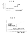
- the stirring force is increased by increasing the rate of injection of the gas as shown in Fig. 6.
- a solid material is injected and is carried by the blowing gas and, in the latter period of the refining process, only the rate of injection of the solid material is increased while the rate of supply of the gas is maintained substantially constant, to achieve an effective control of the stirring force.
- the inventors have made various studies to seek the conditions of blowing the gas and solid material for attaining the optimum stirring effect, and have found that the rate of injection of the solid material should be adjusted such that the sum of the blown gas and the gas generated by the decomposition of the solid material in the second half part (about 50%) of the refining process is 1.5 or more times that in the first half (about 50%) of the refining process. (See Fig. 7).
- the desired stirring force can be obtained by injecting limestone at a rate of less than 1 kg per 1 Nm 3 of the blown gas in the first half period of the refining process and then further injecting limestone (CaC0 3 ) at a rate of more than 5 kg per 1 Nm 3 of the blown gas while maintaining the rate of the gas substantially unchanged.
- the particulate solid material preferably has a particle size less than 1 mm.
- the gas blown from the bottom of the molten metal is, for example, selected from pure oxygen, N 2 , Ar, C0 2 , LDG, BFG, waste gas (combustion exhaust gas), and mixtures thereof.
- limestone CaC0 3
- magnesite MgC0 3
- green dolomite CaC0 3- MgC0 3
- the like can, for example, be used as the solid material.
- the gas volume may be increased through the following reaction, by adding powdered carbon to this solid material.
- a combined top and bottom blown oxygen refining was conducted by injecting particulate limestone (CaC0 3 ), magnesite (MgC0 3 ) and green dolomite from the bottom tuyeres together with the oxygen gas, and the result of the refining was recorded and examined.
- the main raw material used for this refining was 130 tonnes of the molten pig iron and 40 tonnes of scrap iron.
- the molten pig iron contained 4.2% C, 0.35% Si, 0.55% Mn, 0.100% P, 0.015% Sand 0.0040% N, and the temperature of molten pig iron was 1350°C.
- the rate of supply of the pure oxygen from the top lance was maintained constant 30000 Nm 3 /h.
- the patterns of injection of the oxygen and the solid material from the bottom tuyeres were selected such that the sums of the amount of the pure oxygen blown and the amount of gas generated by decomposition of the solid material in all heat cycles were equal.
- the refining time of each heat cycle was about 18 minutes.
- Pure oxygen was blown from the bottom tuyeres at a constant rate of 750 Nm 3 /h, while the rate of injection of the limestone (CaCO 3 ) powder was 500 kg/h from the start of the refining until 50% of the whole refining period, then it was added at 2500 kg/h in the period between 50 and 85% of the whole refining period and finally at 7500 kg/h in the last part, i.e. 85% to 100% (completion of the refining), of the whole refining period.
- the amount of the blown pure oxygen per 1 tonne of the steel was 1.4 Nm 3 while the amount of CO 2 generated from the limestone (CaC0 3 ) was 0.9 Nm 3.
- the rate of supply of gas in the 50 to 85% period of refining was 1.5 times as large as that in the earlier half, i.e. 0 to 50% of refining. Also, the rate of supply of the gas in the 85 to 100% period was about 3 times as large as in the first half of the refining period.
- CO 2 gas was blown from the bottom tuyeres at a constant rate of 750 Nm 3 /h, together with varied rate of powdered magnesite (MgC0 3 ).
- the rate of injection of magnesite was 400 kg/h in the earlier half of the refining and 3400 kg/h in the late half of the refining.
- the amount of blown CO 2 gas per 1 tonne of steel was 1.4 Nm 3
- the amount of CO 2 gas generated from magnesite (MgC0 3 ) was 0.9 Nm 3 .
- the sum of CO 2 gas supplied per 1 tonne of steel was 2.3 Nm 3 . It will be understood that the rate of supply of gas in the later half period was about twice that supplied in the earlier half of refining.
- N 2 gas was blown from the bottom tuyere at a varying rate, 1000 Nm 3 /h from the beginning to 50% of the whole refining period, 1500 Nm 3 Jh between 50 and 85% of the whole refining period and 2200 Nm 3 /h from 85% to 100%, i.e. the end, of the whole refining period.
- the amount of blown N 2 gas was 2.3 Nm 3 per tonne of steel.
- Pure oxygen and limestone powder were injected from the bottom tuyeres at constant rates of 750 Nm 3 /h and 2250 Kg/h, respectively.
- the amount of oxygen gas supplied per 1 tonne of steel was 1.4 Nm 3
- the amount of the limestone was 0.9 Nm 3 per 1 tonne of steel.
- the sum of the gas was 2.3 Nm 3 .
- the rate of supply of the solid material is increased in the latter half part of the refining period to control the rate of generation of the gas from the solid material, while maintaining the gas blowing rate substantially constant, in such a manner that the amount of stirring gas obtained in the latter half period is materially 1.5 or more times as large as that obtained in the earlier half period of refining.
- Table 7 the method of the invention provides a stronger stirring effect on the molten metal and slag, while achieving a higher dephosphorization effect. Also, a high blow-out of Mn and small total Fe contents in the slag are noted.
- the solid material used in the method of this embodiment not only provides the stirring effect through generation of gas but also is effective in that CaO or MgO generated as a result of the decomposition effectively serves as the slag making agent in the refining of iron into steel, and permits reduction of the total amount of CaO and/or MgO usually injected for the purpose of dephosphorization, desulfurization and protection of bricks.
- the generated CO 2 gas can be recovered for further use through a reaction with the carbon in the steel as expressed by the following reaction.
- this embodiment of the invention offers various advantages such as saving of energy, facilitating refining and so forth.
- the solid material used as the source of the stirring gas serves also as a flux for refining, to permit lowering of consumption of the green lime, dolomite or the like.
- the method of this embodiment is advantageous also from the economical point of view, because the generated gas can be recovered and reused as a fuel gas having a high calorific value.
- the method of this embodiment is applicable not only to the described bottom-blown converter refining process but also to a refining process making use of an immersed lance having a gas injection nozzle.
Landscapes
- Engineering & Computer Science (AREA)
- Chemical & Material Sciences (AREA)
- Manufacturing & Machinery (AREA)
- Materials Engineering (AREA)
- Metallurgy (AREA)
- Organic Chemistry (AREA)
- Carbon Steel Or Casting Steel Manufacturing (AREA)
- Treatment Of Steel In Its Molten State (AREA)
Claims (23)
Priority Applications (1)
| Application Number | Priority Date | Filing Date | Title |
|---|---|---|---|
| AT81304470T ATE31551T1 (de) | 1980-09-26 | 1981-09-28 | Verfahren zum vermeiden von schaeden an einer eintauchduese eines ofens zum entkohlen von stahl bei der stahlherstellung. |
Applications Claiming Priority (8)
| Application Number | Priority Date | Filing Date | Title |
|---|---|---|---|
| JP133966/80 | 1980-09-26 | ||
| JP13396780A JPS6050844B2 (ja) | 1980-09-26 | 1980-09-26 | 溶融鉄中への酸素吹込み羽口の保護方法 |
| JP133968/80 | 1980-09-26 | ||
| JP13396880A JPS6027723B2 (ja) | 1980-09-26 | 1980-09-26 | 溶融鉄中への酸素吹込み羽口の保護方法 |
| JP55133966A JPS6027722B2 (ja) | 1980-09-26 | 1980-09-26 | 溶融鉄へのガス吹き込み法 |
| JP133967/80 | 1980-09-26 | ||
| JP2516181A JPS57140810A (en) | 1981-02-23 | 1981-02-23 | Refining method for steel |
| JP25161/81 | 1981-02-23 |
Publications (2)
| Publication Number | Publication Date |
|---|---|
| EP0049148A1 EP0049148A1 (de) | 1982-04-07 |
| EP0049148B1 true EP0049148B1 (de) | 1987-12-23 |
Family
ID=27458262
Family Applications (1)
| Application Number | Title | Priority Date | Filing Date |
|---|---|---|---|
| EP81304470A Expired EP0049148B1 (de) | 1980-09-26 | 1981-09-28 | Verfahren zum Vermeiden von Schäden an einer Eintauchdüse eines Ofens zum Entkohlen von Stahl bei der Stahlherstellung |
Country Status (7)
| Country | Link |
|---|---|
| US (1) | US4388113A (de) |
| EP (1) | EP0049148B1 (de) |
| AU (1) | AU531023B2 (de) |
| BR (1) | BR8106166A (de) |
| CA (1) | CA1170460A (de) |
| DE (1) | DE3176581D1 (de) |
| ES (1) | ES8303534A1 (de) |
Families Citing this family (3)
| Publication number | Priority date | Publication date | Assignee | Title |
|---|---|---|---|---|
| ZA966811B (en) * | 1995-08-18 | 1998-02-12 | Colgate Palmolive Co | Cosmetic gel composition having reduced skin irritation. |
| CN111455127B (zh) * | 2020-05-23 | 2022-02-08 | 苏州大学 | 一种维护底喷粉转炉蘑菇头的吹炼控制方法 |
| CN111500815B (zh) * | 2020-05-28 | 2021-06-11 | 北京科技大学 | 一种底吹O2-CO2-CaO转炉炼钢过程动态控制方法 |
Family Cites Families (10)
| Publication number | Priority date | Publication date | Assignee | Title |
|---|---|---|---|---|
| US2979395A (en) * | 1957-01-22 | 1961-04-11 | Kosmider Johannes | Method of preparing preliminary metal or steel pig iron containing phosphorus |
| US2950186A (en) * | 1957-03-02 | 1960-08-23 | Siderurgie Fse Inst Rech | Method for top blowing pulverulent burnt lime and oxygen into cast iron for refining same |
| FR1243414A (fr) * | 1959-02-27 | 1960-10-14 | Air Liquide | Procédé d'affinage des fontes phosphoreuses par l'oxygène concentré |
| US2991173A (en) * | 1959-02-27 | 1961-07-04 | Siderurgie Fse Inst Rech | Metal refining method and apparatus |
| LU57833A1 (de) * | 1969-01-23 | 1970-07-29 | ||
| LU58309A1 (de) * | 1969-02-27 | 1969-07-15 | ||
| BE748041A (fr) * | 1970-03-26 | 1970-09-28 | Centre Rech Metallurgique | Perfectionnements aux procedes d'affinage, |
| SE395911B (sv) * | 1974-04-16 | 1977-08-29 | Uddeholms Ab | Behandling av metallsmelta i keramiskt infordrat reaktionskerl |
| DE2740842A1 (de) * | 1977-09-10 | 1979-03-22 | Ernst Peter Prof Dipl I Franke | Frischmittel bei bodenblasenden stahlerzeugungsverfahren |
| BE880526A (fr) * | 1979-12-10 | 1980-06-10 | Bristol Myers Company Ct De Re | Sels d'argent d'acide phosphanilique, leur procede de production et composition antibacterienne les contenant. |
-
1981
- 1981-09-24 US US06/305,259 patent/US4388113A/en not_active Expired - Lifetime
- 1981-09-24 ES ES505740A patent/ES8303534A1/es not_active Expired
- 1981-09-25 CA CA000386735A patent/CA1170460A/en not_active Expired
- 1981-09-25 AU AU75681/81A patent/AU531023B2/en not_active Expired
- 1981-09-25 BR BR8106166A patent/BR8106166A/pt not_active IP Right Cessation
- 1981-09-28 DE DE8181304470T patent/DE3176581D1/de not_active Expired
- 1981-09-28 EP EP81304470A patent/EP0049148B1/de not_active Expired
Also Published As
| Publication number | Publication date |
|---|---|
| ES505740A0 (es) | 1983-02-01 |
| US4388113A (en) | 1983-06-14 |
| EP0049148A1 (de) | 1982-04-07 |
| DE3176581D1 (en) | 1988-02-04 |
| CA1170460A (en) | 1984-07-10 |
| AU531023B2 (en) | 1983-08-04 |
| ES8303534A1 (es) | 1983-02-01 |
| BR8106166A (pt) | 1982-06-15 |
| AU7568181A (en) | 1982-04-01 |
Similar Documents
| Publication | Publication Date | Title |
|---|---|---|
| Szekely et al. | Ladle metallurgy | |
| JP5644355B2 (ja) | 溶銑の精錬方法 | |
| KR101018535B1 (ko) | 철합금의 정련 방법 | |
| CA1148746A (en) | Converter steelmaking process | |
| CA1178051A (en) | Gas-blast pipe for feeding reaction agents into metallurgical melts | |
| EP0049148B1 (de) | Verfahren zum Vermeiden von Schäden an einer Eintauchdüse eines Ofens zum Entkohlen von Stahl bei der Stahlherstellung | |
| JPH0256407B2 (de) | ||
| KR20230136164A (ko) | 용철의 정련 방법 및 그것을 이용한 용강의 제조 방법 | |
| US3859078A (en) | Method of operating a basic open hearth furnace | |
| JP5915568B2 (ja) | 転炉型精錬炉における溶銑の精錬方法 | |
| US4891064A (en) | Method of melting cold material including iron | |
| CA1157660A (en) | Method for producing steel having a low hydrogen content in an oxygen blow-through converter | |
| US2741554A (en) | Method of refining iron | |
| US4394165A (en) | Method of preliminary desiliconization of molten iron by injecting gaseous oxygen | |
| KR860001523B1 (ko) | 제강공정에서 탈탄 정련로의 송풍구의 손상 방지법 | |
| JPH0723494B2 (ja) | 溶融金属の精錬方法及びその装置 | |
| JPS6250544B2 (de) | ||
| JPS6138249B2 (de) | ||
| US3028232A (en) | Process for blowing pig-iron | |
| CA2103266A1 (en) | A method for blowing oxidizing gases into molten metal | |
| US4171216A (en) | Process for refining non-ferrous matte | |
| KR100225249B1 (ko) | 슬로핑 발생 억제를 위한 잔류 슬래그량 조절방법 | |
| JP7852660B2 (ja) | 溶銑の予備処理方法 | |
| US3374088A (en) | Method for producing low silicon ferromanganese alloys | |
| Dutta et al. | Oxygen Steelmaking Processes |
Legal Events
| Date | Code | Title | Description |
|---|---|---|---|
| PUAI | Public reference made under article 153(3) epc to a published international application that has entered the european phase |
Free format text: ORIGINAL CODE: 0009012 |
|
| AK | Designated contracting states |
Designated state(s): AT BE DE FR GB IT LU NL SE |
|
| 17P | Request for examination filed |
Effective date: 19820902 |
|
| GRAA | (expected) grant |
Free format text: ORIGINAL CODE: 0009210 |
|
| AK | Designated contracting states |
Kind code of ref document: B1 Designated state(s): AT BE DE FR GB IT LU NL SE |
|
| REF | Corresponds to: |
Ref document number: 31551 Country of ref document: AT Date of ref document: 19880115 Kind code of ref document: T |
|
| REF | Corresponds to: |
Ref document number: 3176581 Country of ref document: DE Date of ref document: 19880204 |
|
| ET | Fr: translation filed | ||
| ITF | It: translation for a ep patent filed | ||
| PLBE | No opposition filed within time limit |
Free format text: ORIGINAL CODE: 0009261 |
|
| STAA | Information on the status of an ep patent application or granted ep patent |
Free format text: STATUS: NO OPPOSITION FILED WITHIN TIME LIMIT |
|
| 26N | No opposition filed | ||
| ITTA | It: last paid annual fee | ||
| EPTA | Lu: last paid annual fee | ||
| EAL | Se: european patent in force in sweden |
Ref document number: 81304470.8 |
|
| PGFP | Annual fee paid to national office [announced via postgrant information from national office to epo] |
Ref country code: SE Payment date: 20000906 Year of fee payment: 20 |
|
| PGFP | Annual fee paid to national office [announced via postgrant information from national office to epo] |
Ref country code: FR Payment date: 20000912 Year of fee payment: 20 |
|
| PGFP | Annual fee paid to national office [announced via postgrant information from national office to epo] |
Ref country code: AT Payment date: 20000913 Year of fee payment: 20 |
|
| PGFP | Annual fee paid to national office [announced via postgrant information from national office to epo] |
Ref country code: DE Payment date: 20000918 Year of fee payment: 20 |
|
| PGFP | Annual fee paid to national office [announced via postgrant information from national office to epo] |
Ref country code: LU Payment date: 20000925 Year of fee payment: 20 |
|
| PGFP | Annual fee paid to national office [announced via postgrant information from national office to epo] |
Ref country code: GB Payment date: 20000927 Year of fee payment: 20 |
|
| PGFP | Annual fee paid to national office [announced via postgrant information from national office to epo] |
Ref country code: NL Payment date: 20000928 Year of fee payment: 20 |
|
| PGFP | Annual fee paid to national office [announced via postgrant information from national office to epo] |
Ref country code: BE Payment date: 20001117 Year of fee payment: 20 |
|
| BE20 | Be: patent expired |
Free format text: 20010928 *NIPPON STEEL CORP. |
|
| PG25 | Lapsed in a contracting state [announced via postgrant information from national office to epo] |
Ref country code: GB Free format text: LAPSE BECAUSE OF EXPIRATION OF PROTECTION Effective date: 20010927 |
|
| PG25 | Lapsed in a contracting state [announced via postgrant information from national office to epo] |
Ref country code: NL Free format text: LAPSE BECAUSE OF EXPIRATION OF PROTECTION Effective date: 20010928 Ref country code: LU Free format text: LAPSE BECAUSE OF EXPIRATION OF PROTECTION Effective date: 20010928 Ref country code: AT Free format text: LAPSE BECAUSE OF EXPIRATION OF PROTECTION Effective date: 20010928 |
|
| PG25 | Lapsed in a contracting state [announced via postgrant information from national office to epo] |
Ref country code: SE Free format text: THE PATENT HAS BEEN ANNULLED BY A DECISION OF A NATIONAL AUTHORITY Effective date: 20010929 |
|
| REG | Reference to a national code |
Ref country code: GB Ref legal event code: PE20 Effective date: 20010927 |
|
| EUG | Se: european patent has lapsed |
Ref document number: 81304470.8 |
|
| NLV7 | Nl: ceased due to reaching the maximum lifetime of a patent |
Effective date: 20010928 |