EP0049519A2 - Bloc cylindres pour moteur - Google Patents
Bloc cylindres pour moteur Download PDFInfo
- Publication number
- EP0049519A2 EP0049519A2 EP81107992A EP81107992A EP0049519A2 EP 0049519 A2 EP0049519 A2 EP 0049519A2 EP 81107992 A EP81107992 A EP 81107992A EP 81107992 A EP81107992 A EP 81107992A EP 0049519 A2 EP0049519 A2 EP 0049519A2
- Authority
- EP
- European Patent Office
- Prior art keywords
- section
- cylinder block
- engine
- cylinder
- skirt section
- Prior art date
- Legal status (The legal status is an assumption and is not a legal conclusion. Google has not performed a legal analysis and makes no representation as to the accuracy of the status listed.)
- Granted
Links
Images


Classifications
-
- F—MECHANICAL ENGINEERING; LIGHTING; HEATING; WEAPONS; BLASTING
- F02—COMBUSTION ENGINES; HOT-GAS OR COMBUSTION-PRODUCT ENGINE PLANTS
- F02F—CYLINDERS, PISTONS OR CASINGS, FOR COMBUSTION ENGINES; ARRANGEMENTS OF SEALINGS IN COMBUSTION ENGINES
- F02F7/00—Casings, e.g. crankcases
- F02F7/0065—Shape of casings for other machine parts and purposes, e.g. utilisation purposes, safety
- F02F7/008—Sound insulation
-
- F—MECHANICAL ENGINEERING; LIGHTING; HEATING; WEAPONS; BLASTING
- F02—COMBUSTION ENGINES; HOT-GAS OR COMBUSTION-PRODUCT ENGINE PLANTS
- F02F—CYLINDERS, PISTONS OR CASINGS, FOR COMBUSTION ENGINES; ARRANGEMENTS OF SEALINGS IN COMBUSTION ENGINES
- F02F7/00—Casings, e.g. crankcases
- F02F7/0043—Arrangements of mechanical drive elements
- F02F7/0053—Crankshaft bearings fitted in the crankcase
- F02F2007/0056—Crankshaft bearings fitted in the crankcase using bearing beams, i.e. bearings interconnected by a beam or multiple beams
Definitions
- This invention relates generally to an improvement in a cylinder block for an internal combustion engine, and more particularly to a cylinder block construction to effective to reduce the vibration-noise radiated therefrom to achieve total engine noise reduction.
- a cylinder block to which a cylinder head and an oil pan are secured has an upper section having therein a plurality of engine cylinder bores, and a lower section or skirt section which is generally bulged outwardly to form thereinside a crankcase for an engine crankshaft.
- the cylinder block thereof vibrates due to fuel combustion pressure and reciprocal engine piston movement.
- this cylinder block vibration causes the skirt section to vibrate, thus radiating a considerable high-level noise from the surface of the skirt section.
- Such vibrations of the cylinder block are considered to result from shortage in torsional and flexural rigidities of the cylinder block.
- a cylinder block is composed of an upper section having a plurality of engine cylinder bores therein.
- the upper section has first and second oppositely disposed wall memers.
- a skirt section is integrally connected to the upper section and has a cavity defining a crankcase for an engine crankshaft.
- the cylinder block is constructed and arranged to prevent the vibration of the skirt section and increase the tortional and flexural rigidities of the cylinder block. This has been achieved, for example, by arranging the first and second walls of the skirt section in straight alignment with the first and second wall members of the upper section, respectively.
- the torsional and flexural rigidities of the cylinder block are greatly improved, thereby effectively preventing the upper section and the skirt section from vibration. Additionally, the surface area of the skirt section is decreased as compared with that of conventional cylinder block. Therefore, noise to be radiated from the cylinder block can be greatly reduced, effectively achieving total engine noise reduction.
- the cylinder block is composed of opposite upper side walls 1 each of which defines thereinside a water jacket 3 formed around a cylinder row structure including a plurality of cylinder (liner) sections 2.
- Each cylinder section 2 is formed therein with an engine cylinder bore in which an engine piston will be movably disposed.
- a skirt section 4 defining thereinside a crankcase is integrally connected to the upper side walls 1. The skirt section 4 is bulged so that the inner surface thereof is slight spaced from and along the envelope of the outer-most loci of a big end of a connecting rod.
- the reference numeral 5 denotes main bearing caps for rotatably supporting a crankshaft. It is to be noted that the upper side walls are generally parallel with a plane containing axes of the engine cylinder bores, and the connecting section 6 through which the skirt section integrally connected to each upper side wall 1 is formed into the arcuate shape in cross-section. It will be understood that a cylinder head (no numeral) is secured through a gasket onto the top surface of the cylinder block by means of bolts so as to define a combustion chamber within the cylinder bore, and an oil pan is secured to the bottom part of the skirt section 4.
- the connecting section 6 of the upper side wall 1 and the skirt section 4 is not sufficient in connection rigidity, and therefore the cylinder block can be twisted in the directions of arrows a and b and bended in the directions of arrows c and d by the vibration caused due to explosiion or combustion of air-fuel mixture during engine operation and transmitted to the cylinder block.
- Such movements of the cylinder block generate considerable vibration noise.
- the skirt section 4 itself also vibrates, thereby generating vibration noise.
- the conventional cylinder block of the above-discussed type high and sufficient tortional and flexual rigidities cannot be obtained, thus greatly contributing to undesirable total engine noise increase.
- a preferred embodiment of a cylinder block of an automotive internal combustion engin is illustrated by the reference numeral 10.
- the cylinder block 10 comprises two upper side walls or water jacket outer walls 12A, 12B which are located opposite to each other and enclose therebetween a cylinder row structure 14.
- the cylinder row structure 14 has a plurality of cylinder (liner) sections 16 each of which is formed therein with an engine cylinder bore B within which an engine piston will be movably disposed.
- the plurality of cylinder sections 16 are integrally connected with each other.
- a water jacket 18A is formed between the water jacket outer wall 12A and the cylinder row structure 14, and another water jacket 18B is formed between the water jacket outer wall 12B and the cylinder row structure 16.
- An engine coolant will flow through the water jackets 18A, 18B to cool each engine cylinder section 16.
- a skirt section 20 of the cylinder block 10 has two oppositely disposed counterparts or walls 20a, 20b.
- the skirt section counterpart 20a is integrally connected to the water jacket outer wall 12A in such a manner that the water jacket outer wall 12A and the skirt section counterpart 20a are in generally straight alignment with each other at least an area near an imaginery connecting section C at which the both 12A, 20a seem to be integrally connected.
- the skirt section counterpart 20b is likewise integrally connected to the water jacket outer wall 12B.
- the cylinder block 10 is generally in the shape of isosceles trapezoid in cross-section taken along a vertical plane to which the axis of the cylinder block is perpendicular as shown in Figs.
- each water jacket outer wall 12A, 12B In order to obtain the necessary width of the water jacket (i.e., the distance between the outer wall surface of cylinder sections 16 and the inner surface of water jacket outer wall 12A, 12B) of at least 6 mm/ the upper part of each water jacket outer wall 12A, 12B is formed into the cylindrical shape and parallel with the cylinder section 16 in the vicinity of an imaginary vertical plane (cross-sectional plane) 3-3 shown in Fig. 2.
- the reference numeral 22 denotes main bearing caps each of which is secured to each bearing bulk or bearing support section 23 forming part of the cylinder block 10.
- the bearing bulk 23 is integral with the cylinder block 20.
- a cylindrical opening (no numeral) for rotatably supporting therein a crankshaft (no numeral) is defined between the bearing bulk 23 and the main bearing cap 22.
- the isosceles trapezoid shape cylinder block 10 sufficient torsional and flexural rigidities can be obtained, thereby effectively suppressing the generation of vibration noises at the various parts of the cylinder block 10. Additionally, the generation of vibration noise from an oil pan 21 secured to the skirt section 20 can also be effectively suppressed. Due to the fact that the skirt section 20 is formed flat, the surface area of the skirt section 20 is considerably small as compared with the conventional bulged skirt section 4 as shown in Fig. 1, and therefore the natural frequency of the skirt section 20 increases, thereby greatly reducing the energy of noise radiated from the skirt section 20.
- the cylinder block 10 is formed integrally with cylinder head installation boss sections 24 each of which has a hole 26 to which a cylinder head bolt (not shown) is inserted so as to secure a cylinder head (not shown) onto the top surface of the cylinder block 10.
- each boss section 24 is further integrally connected through a rib 28 to the inner surface of the water jacket outer wall 12A, 12B.
- the skirt section 20 is formed at its bottom with a relatively wide flange 20c to which an oil pan 21 is secured, so that the flexural rigidity of the cylinder block 10 in its lateral direction can be considerably improved.
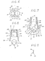
- Fig. 5 to 9 illustrate another embodiment of the cylinder block 10 in accordance with the present invention, which is similar to the embodiment of Figs. 2 to 4 except a bearing beam structure 30 located in place of the main bearing caps 22 of the embodiment of Figs. 2 to 4.
- the bearing beam structure 30 is composed of a plurality of bearing cap sections 32.
- Each bearing cap section 32 is formed with a semicylindrical bearing support recess 32a.
- the bearing cap sections 32 are integrally connected through a beam section 34 with each other.
- the beam section 34 extends along the axis of the crankshaft and is usually made by integrally casting the beam section 34 with the bearing cap sections 32.
- each bearing cap section 32 of the bearing beam structure 30 are respectively secured to the bearing bulks 23 by means of bolts 35, in which a cylindrical opening for supporting the crankshaft is defined by a semicylindrical bearing support recess 23a of each bearing bulk 23 and the above-mentioned recess 32a of each bearing cap section 32. It will be understood that each bearing cap section 32 and the beam section 34 may be separately prepared as independent pieces, and thereafter securely connected with each other, for example, by means of bolts.
- the cylinder block 10 is further integrally formed with a transmission installation section 36 to which a transmission T is securely connected.
- this transmission installation section 36 contributes to an improvement in the flexural rigidity of the cylinder block 10 in its lateral direction in addition to the wider oil pan installation flange 20c.
- a rib 38 may be formed integrally with and along the flange 20c of each skirt section counterpart 20a, 20b as shown in Fig. 9.
- the bearing beam structure 30 can effectively suppress the vibration of the bearing cap section 32 in the direction that the bearing cap sections 32 come down, i.e., in the direction of the axis of the cylinder block 10. This reduces the vibration to be applied to the skirt section 20, thus further decreasing noise to be radiated from the skirt section 20.
- Such vibration reduction of the skirt section 20 contributes to the vibration reduction of the oil pan 21, thereby effectively decreasing noise to be radiated from the oil pan 21.
- the cylinder block 10 itself is provided with a sufficient rigidity against flexure, torsion and the like applied thereto, and therefore it is unnecessary to take such rigidities into account in designing the bearing beam structure 30.
- the bearing structure 30 has a minimum dimension enough to suppress the above-mentioned coming-down vibration of the bearing cap sections 32. As a result, noise reduction can be very effectively achieved without noticeable engine weight increase.
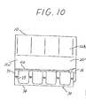
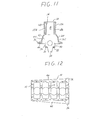
- Figs. 10 to 12 illustrate a further embodiment of the cylinder block in accordance with the present invention, in which the skirt section 20' is curved at its surface or bulged outwardly.
- each of the oppositely disposed walls 20a', 20b' of the skirt section 20' is formed integrally at its outer surface with a flange-like reinforcement rib 40 which extends along the axis of the crankshaft or of the cylindrical opening for the crankshaft.
- the reinforcement rib 10 is so located as to be the same level as the axis of the crankshaft and projects generally horizontally relative to the cylinder block 10.
- the reinforcement rib 40 extends along the axis of the crankshaft from the front end of the cylinder block 10 to the rear end of the same, so that the reinforcement rib 40 is integrally connected to the transmission installation section 36.
- the reinforcement rib 40 is formed so that its thickness and width (projection width) gradually increase from the front end thereof toward the rear end thereof as shown in Fig. 12. This contributes to engine weight lightening, meeting such a requirement that the rear section of the cylinder block 10 should be great in weight and high in rigidity as compared with the front section thereof.
- the cylinder block 10 of this instance is reinforced by employing the bearing beam structure 30 which is the same as in the embodiment of Figs. 5 to 9.
- the bearing beam structure 30 is mainly effective against the flexure in the upward and downward directions of the cylinder block 10
- the reinforcement rib 40 is mainly effective against the flexure in the lateral directions of the cylinder block 10.
- the cooperation of the bearing beam structure 30 and the reinforcement rib 40 is effective against the torsion applied to the cylinder block 10.
- the reinforcement rib 40 is continuously connected to the transmission installation section 36, the connection rigidity between the cylinder block 10 and the transmission is improved, thereby noticeably reducing low frequency noise generating within a passenger compartment, and extending the maximum cirtical engine speed.
- the cylinder block itself has a sufficient rigidity against the flexure in the lateral direction, and therefore it is unnecessary to take such flexural digidity into account in designing the beam section 34 of the bearing beams structure 30. Accordingly, it is sufficient that the beam section 34 of the bearing beam structure 30 has the minimum dimention enough to suppress the above-mentioned coming-down vibration of the bearing cap sections 32. As a result, noise reduction can be effectively attained, achieving engine weight lightening.
- cylinder blocks which are not provided with a so-called upper deck, i.e., cylinder blocks whose water jackets formed in the cylinder block will communicate with an engine coolant passage formed in the cylinder head, in which the weight lightening advantage due to this type of cylinder block can be maintained.
Landscapes
- Engineering & Computer Science (AREA)
- Chemical & Material Sciences (AREA)
- Combustion & Propulsion (AREA)
- Mechanical Engineering (AREA)
- General Engineering & Computer Science (AREA)
- Cylinder Crankcases Of Internal Combustion Engines (AREA)
Applications Claiming Priority (4)
| Application Number | Priority Date | Filing Date | Title |
|---|---|---|---|
| JP14298980U JPS601248Y2 (ja) | 1980-10-07 | 1980-10-07 | 自動車用エンジン |
| JP142989/80U | 1980-10-07 | ||
| JP14299180U JPS6120279Y2 (fr) | 1980-10-07 | 1980-10-07 | |
| JP142991/80U | 1980-10-07 |
Related Child Applications (1)
| Application Number | Title | Priority Date | Filing Date |
|---|---|---|---|
| EP85101183.3 Division-Into | 1981-10-06 |
Publications (3)
| Publication Number | Publication Date |
|---|---|
| EP0049519A2 true EP0049519A2 (fr) | 1982-04-14 |
| EP0049519A3 EP0049519A3 (en) | 1982-10-27 |
| EP0049519B1 EP0049519B1 (fr) | 1987-09-16 |
Family
ID=26474832
Family Applications (2)
| Application Number | Title | Priority Date | Filing Date |
|---|---|---|---|
| EP85101183A Expired - Lifetime EP0152857B1 (fr) | 1980-10-07 | 1981-10-06 | Bloc-cylindre d'un moteur |
| EP81107992A Expired EP0049519B1 (fr) | 1980-10-07 | 1981-10-06 | Bloc cylindres pour moteur |
Family Applications Before (1)
| Application Number | Title | Priority Date | Filing Date |
|---|---|---|---|
| EP85101183A Expired - Lifetime EP0152857B1 (fr) | 1980-10-07 | 1981-10-06 | Bloc-cylindre d'un moteur |
Country Status (3)
| Country | Link |
|---|---|
| US (2) | US4452192A (fr) |
| EP (2) | EP0152857B1 (fr) |
| DE (2) | DE3177171D1 (fr) |
Families Citing this family (3)
| Publication number | Priority date | Publication date | Assignee | Title |
|---|---|---|---|---|
| DE9319055U1 (de) * | 1993-12-11 | 1995-04-13 | FEV Motorentechnik GmbH & Co. KG, 52078 Aachen | Kolbenmaschine, insbesondere Kolbenbrennkraftmaschine mit versteiftem Motorblock mittels unterbrochener Rippen |
| US7219642B1 (en) * | 2006-02-10 | 2007-05-22 | Gm Global Technology Operations, Inc. | Powertrain assembly and integral truss oil pan therefor |
| US9086031B2 (en) | 2013-03-12 | 2015-07-21 | Ford Global Technologies, Llc | Cracked cap bulkhead insert |
Family Cites Families (16)
| Publication number | Priority date | Publication date | Assignee | Title |
|---|---|---|---|---|
| GB294766A (en) * | 1927-07-20 | 1928-08-02 | George Cassady | Improvements in and relating to hydraulic variable speed gearing |
| US2098451A (en) * | 1936-07-18 | 1937-11-09 | Gilmore Harry | Method of strengthening crankcases |
| US2701553A (en) * | 1951-03-10 | 1955-02-08 | Maschf Augsburg Nuernberg Ag | Bed for internal-combustion engines |
| US2681054A (en) * | 1951-04-06 | 1954-06-15 | Kaiser Motors Corp | Construction of die-cast cylinder blocks |
| DE1104268B (de) * | 1958-03-07 | 1961-04-06 | Goetaverken Ab | Maschinengestell fuer Kolbenmaschinen |
| US3046954A (en) * | 1961-01-18 | 1962-07-31 | Gen Motors Corp | Crankcase and bearing structure for internal combustion engines |
| GB1294766A (en) * | 1970-07-03 | 1972-11-01 | Birmid Qualcast Foundries Ltd | Internal combustion engine |
| AT343958B (de) * | 1975-09-04 | 1978-06-26 | List Hans | Mehrzylinder-brennkraftmaschine |
| US4245595A (en) * | 1977-09-13 | 1981-01-20 | Nissan Motor Company, Limited | Internal combustion engine for motor vehicles |
| JPS5823492B2 (ja) * | 1977-11-17 | 1983-05-16 | 日産自動車株式会社 | 自動車用低騒音エンジン |
| JPS5950864B2 (ja) * | 1977-11-26 | 1984-12-11 | 日産自動車株式会社 | 自動車用エンジン |
| DE2834089C2 (de) * | 1978-08-03 | 1982-09-23 | International Harvester Company Mbh, 4040 Neuss | Brennkraftmaschine |
| AT374569B (de) * | 1979-02-07 | 1984-05-10 | List Hans | Brennkraftmaschine |
| JPS5697535U (fr) * | 1979-12-25 | 1981-08-01 | ||
| JPS5949419B2 (ja) * | 1980-12-11 | 1984-12-03 | 日産自動車株式会社 | 自動車用エンジン |
| JPS5840538U (ja) * | 1981-09-09 | 1983-03-17 | 日産自動車株式会社 | シリンダブロツク |
-
1981
- 1981-10-06 DE DE8585101183T patent/DE3177171D1/de not_active Expired - Lifetime
- 1981-10-06 EP EP85101183A patent/EP0152857B1/fr not_active Expired - Lifetime
- 1981-10-06 DE DE8181107992T patent/DE3176451D1/de not_active Expired
- 1981-10-06 EP EP81107992A patent/EP0049519B1/fr not_active Expired
- 1981-10-07 US US06/309,386 patent/US4452192A/en not_active Expired - Lifetime
-
1984
- 1984-01-26 US US06/574,273 patent/US4569317A/en not_active Expired - Lifetime
Also Published As
| Publication number | Publication date |
|---|---|
| DE3176451D1 (en) | 1987-10-22 |
| US4452192A (en) | 1984-06-05 |
| EP0152857A3 (en) | 1985-12-11 |
| EP0049519B1 (fr) | 1987-09-16 |
| EP0152857A2 (fr) | 1985-08-28 |
| US4569317A (en) | 1986-02-11 |
| EP0152857B1 (fr) | 1990-04-11 |
| DE3177171D1 (de) | 1990-05-17 |
| EP0049519A3 (en) | 1982-10-27 |
Similar Documents
| Publication | Publication Date | Title |
|---|---|---|
| US4467754A (en) | Automotive internal combustion engine | |
| EP0052818B1 (fr) | Bloc-cylindre pour un moteur à combustion interne | |
| EP0076474A1 (fr) | Moteur d'automobile à combustion interne avec un châssis de poutres à support de palier | |
| EP0077033B1 (fr) | Châssis de poutres à support de palier | |
| US4466401A (en) | Internal combustion engine with bearing beam structure | |
| EP0088339B1 (fr) | Chassis à poutres à support de palier pour un moteur à combustion interne | |
| US4473042A (en) | Cylinder block | |
| US4452192A (en) | Cylinder block of engine | |
| US4520771A (en) | Internal combustion engine | |
| US4474148A (en) | Internal combustion engine with bearing beam structure | |
| EP0057869A2 (fr) | Moteur à combustion interne raccordé avec boite à vitesses | |
| EP0056347A2 (fr) | Moteur à combustion interne à bas niveau de bruit | |
| US4445472A (en) | Internal combustion engine with bearing beam structure | |
| US4454842A (en) | Internal combustion engine with bearing beam structure | |
| US4445471A (en) | Low noise level automotive internal combustion engine | |
| JP2606040B2 (ja) | エンジンのシリンダボディ | |
| JPS6313407Y2 (fr) | ||
| JPS601248Y2 (ja) | 自動車用エンジン | |
| JPH0324817Y2 (fr) | ||
| JP2517420Y2 (ja) | エンジンの騒音防止構造 | |
| JPS6218678Y2 (fr) | ||
| JPH0452458Y2 (fr) | ||
| JPS5937247A (ja) | 自動車用エンジンのシリンダブロツク | |
| JPS6336418B2 (fr) |
Legal Events
| Date | Code | Title | Description |
|---|---|---|---|
| PUAI | Public reference made under article 153(3) epc to a published international application that has entered the european phase |
Free format text: ORIGINAL CODE: 0009012 |
|
| AK | Designated contracting states |
Designated state(s): DE FR GB IT |
|
| PUAL | Search report despatched |
Free format text: ORIGINAL CODE: 0009013 |
|
| AK | Designated contracting states |
Designated state(s): DE FR GB IT |
|
| 17P | Request for examination filed |
Effective date: 19820928 |
|
| RAP1 | Party data changed (applicant data changed or rights of an application transferred) |
Owner name: NISSAN MOTOR CO., LTD. |
|
| GRAA | (expected) grant |
Free format text: ORIGINAL CODE: 0009210 |
|
| AK | Designated contracting states |
Kind code of ref document: B1 Designated state(s): DE FR GB IT |
|
| PG25 | Lapsed in a contracting state [announced via postgrant information from national office to epo] |
Ref country code: IT Free format text: LAPSE BECAUSE OF FAILURE TO SUBMIT A TRANSLATION OF THE DESCRIPTION OR TO PAY THE FEE WITHIN THE PRESCRIBED TIME-LIMIT;WARNING: LAPSES OF ITALIAN PATENTS WITH EFFECTIVE DATE BEFORE 2007 MAY HAVE OCCURRED AT ANY TIME BEFORE 2007. THE CORRECT EFFECTIVE DATE MAY BE DIFFERENT FROM THE ONE RECORDED. Effective date: 19870916 Ref country code: FR Free format text: THE PATENT HAS BEEN ANNULLED BY A DECISION OF A NATIONAL AUTHORITY Effective date: 19870916 |
|
| REF | Corresponds to: |
Ref document number: 3176451 Country of ref document: DE Date of ref document: 19871022 |
|
| EN | Fr: translation not filed | ||
| PLBI | Opposition filed |
Free format text: ORIGINAL CODE: 0009260 |
|
| PLBI | Opposition filed |
Free format text: ORIGINAL CODE: 0009260 |
|
| 26 | Opposition filed |
Opponent name: KLOECKNER-HUMBOLDT-DEUTZ AG Effective date: 19880513 |
|
| 26 | Opposition filed |
Opponent name: DAIMLER-BENZ AKTIENGESELLSCHAFT Effective date: 19880615 Opponent name: KLOECKNER-HUMBOLDT-DEUTZ AG Effective date: 19880513 |
|
| PLBN | Opposition rejected |
Free format text: ORIGINAL CODE: 0009273 |
|
| STAA | Information on the status of an ep patent application or granted ep patent |
Free format text: STATUS: OPPOSITION REJECTED |
|
| 27O | Opposition rejected |
Effective date: 19901016 |
|
| PGFP | Annual fee paid to national office [announced via postgrant information from national office to epo] |
Ref country code: DE Payment date: 20001002 Year of fee payment: 20 |
|
| PGFP | Annual fee paid to national office [announced via postgrant information from national office to epo] |
Ref country code: GB Payment date: 20001004 Year of fee payment: 20 |
|
| PG25 | Lapsed in a contracting state [announced via postgrant information from national office to epo] |
Ref country code: GB Free format text: LAPSE BECAUSE OF EXPIRATION OF PROTECTION Effective date: 20011005 |
|
| REG | Reference to a national code |
Ref country code: GB Ref legal event code: PE20 Effective date: 20011005 |
|
| APAH | Appeal reference modified |
Free format text: ORIGINAL CODE: EPIDOSCREFNO |