EP0049552A1 - Dispositif pour bobiner des matériaux flexibles filiformes, en particulier des tuyaux ou des câbles - Google Patents
Dispositif pour bobiner des matériaux flexibles filiformes, en particulier des tuyaux ou des câbles Download PDFInfo
- Publication number
- EP0049552A1 EP0049552A1 EP81201117A EP81201117A EP0049552A1 EP 0049552 A1 EP0049552 A1 EP 0049552A1 EP 81201117 A EP81201117 A EP 81201117A EP 81201117 A EP81201117 A EP 81201117A EP 0049552 A1 EP0049552 A1 EP 0049552A1
- Authority
- EP
- European Patent Office
- Prior art keywords
- reel
- core
- guiding
- coiled
- ledge
- Prior art date
- Legal status (The legal status is an assumption and is not a legal conclusion. Google has not performed a legal analysis and makes no representation as to the accuracy of the status listed.)
- Granted
Links
- 239000000463 material Substances 0.000 title claims abstract description 67
- 239000002131 composite material Substances 0.000 claims abstract description 17
- 229920003023 plastic Polymers 0.000 claims description 11
- 239000004033 plastic Substances 0.000 claims description 11
- 238000006073 displacement reaction Methods 0.000 claims description 5
- 230000001154 acute effect Effects 0.000 claims description 3
- 238000004804 winding Methods 0.000 description 19
- 238000004519 manufacturing process Methods 0.000 description 3
- 230000015572 biosynthetic process Effects 0.000 description 1
- 238000010516 chain-walking reaction Methods 0.000 description 1
- 230000006835 compression Effects 0.000 description 1
- 238000007906 compression Methods 0.000 description 1
- 238000000034 method Methods 0.000 description 1
Images
Classifications
-
- B—PERFORMING OPERATIONS; TRANSPORTING
- B65—CONVEYING; PACKING; STORING; HANDLING THIN OR FILAMENTARY MATERIAL
- B65H—HANDLING THIN OR FILAMENTARY MATERIAL, e.g. SHEETS, WEBS, CABLES
- B65H54/00—Winding, coiling, or depositing filamentary material
- B65H54/02—Winding and traversing material on to reels, bobbins, tubes, or like package cores or formers
- B65H54/28—Traversing devices; Package-shaping arrangements
-
- B—PERFORMING OPERATIONS; TRANSPORTING
- B65—CONVEYING; PACKING; STORING; HANDLING THIN OR FILAMENTARY MATERIAL
- B65H—HANDLING THIN OR FILAMENTARY MATERIAL, e.g. SHEETS, WEBS, CABLES
- B65H54/00—Winding, coiling, or depositing filamentary material
- B65H54/56—Winding of hanks or skeins
- B65H54/58—Swifts or reels adapted solely for the formation of hanks or skeins
-
- B—PERFORMING OPERATIONS; TRANSPORTING
- B65—CONVEYING; PACKING; STORING; HANDLING THIN OR FILAMENTARY MATERIAL
- B65H—HANDLING THIN OR FILAMENTARY MATERIAL, e.g. SHEETS, WEBS, CABLES
- B65H2701/00—Handled material; Storage means
- B65H2701/30—Handled filamentary material
- B65H2701/33—Hollow or hose-like material
- B65H2701/331—Hollow or hose-like material leaving an extruder
Definitions
- the invention relates to an apparatus for coiling to packages flexible elongated materials, particularly tubes or cables, more particularly plastics corrugated tubes, consisting of a frame comprising one or more driveable reels and a guiding device for the material to be coiled upon a reel.
- said material is usually coiled, with a certain pre-tension, upon the core of a reel, the material being guided in axial direction by means of a reciprocating movable guide eye so that the windings upon the reel may adjoin each other as close as possible.
- a pressure plate is used for coiling the material upon a reel in order to retain the windings upon the core of said reel as tightly as possible.
- the prior art apparatus is, however, less suitable for coiling plastics corrugated tubes, although it could be used formerly with a low speed extruder for manufacturing said plastics corrugated tubes.
- the invention aims to provide coiling apparatus which provides at any moment a sufficient support of the tubes to be coiled in order to accurately guide and dispose the windings upon the reel.
- a composite guiding device is provided, one component of which is adapted to dispose or to release the material in a radial direction of the reel, a second component being adapted to enclose or to release said material in an axial direction of the reel.
- the composite guiding device consists of a pressure member extending tangentially with respect to the reel core and being movable towards said reel core thereby exerting a certain pressure, whilst the material to be coiled upon said core can be moved away from said core.
- the latter enables the windings of a corrugated tube, to be coiled upon a reel, to be disposed accurately beside each other, by means of the pressure member, said pressure member being automatically urged sidewardly by the coiled material by the end of a coiled layer in order to dispose a subsequent layer while being guided by the pressure member in a returning movement. From the latter it follows that an additional drive of the guiding member is not required.
- one component of the composite guiding device for radially disposing or releasing material coiled upon the reel comprises movably supported parts of the reel core, the other component, for enclosing the material in axial direction of the reels and releasing the same, consisting of pivotably supported swinging arms which move away from each other into a radial position or T move towards each other into a retracted position in which said swinging arms making an acute angle with the shaft of the reel or are parallel thereto, and the arms in their radial position forming a side face of the reel.
- the material in the form of a corrugated tube (more particularly a plastics corrugated tube) can be coiled tightly upon the reel, although a quick release of the formed package of the material can be effected.
- the apparatus is carried out such, that the composite guiding device is a device mounted upon a swinging arm and surrounding the material to be coiled, said device being recoprocating with respect to #he reel core and allowing, in a position away from said reel core, a displacement in axial direction of the material near the reel.
- Said embodiment is particularly suitable when the swinging arm has been mounted centrally, between two spaced reels and the device surrounding the material can be swung from a central position, both towards one or towards the other reel core.
- the material upon the other reel can then be tightened to each other by wrapping it by means of, for example, separate bands or cards, and be removed from the reel core without any interruption in the production, which operation provides the advantage that there will not occur any disturbances or interruptions at the high productive speeds.
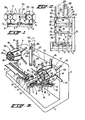
- the apparatus as shown in the drawing consists of a base 1, with a box-shaped frame 2, in which driving devices for two reels 3a and 3b have been mounted.
- the reels 3a and 3b operate alternatively, that is to say, when material is4being coiled upon one reel, the other reel, supporting a package of material having been coiled upon it, is stationary in order to allow the coiled up package to be wrapped by a band or card in order to retain the windings close and tightly to each other when said package as a whole is removed from the reel. Thereupon said reel is ready to be put into operation again after the package on the other reel has been completed.
- a guiding device for coiling material upon one of reels 3a, 3b, respectively which guiding device is, according to the invention, a composite guiding device.
- One component of it is adapted to dispose material in radial direction of the reel, or to release said material, the other component being adapted to enclose said material in axial direction of the reel or to release the material.
- the composite guiding device may comprise a pressure member 5 extending tangentially with the reel core 4, being urged with a certain pressure towards said reel core and being movable away from it by material to be coiled upon the core.
- Said guiding device may, more particularly, be a ledge 5 extending tangentially with respect to the reel core 4. It is movable in axial direction with respect to said core under the influence of a force exerted by the material to be coiled. Such force is exerted upon a side face of ledge 5 being positioned transversely to the core axis.
- ledge 5 in the position represented in fig.
- Ledge 5 is confined between reel core 4, or material having been coiled hereupon, and a plate 6 extending tangentially with the coiling core and having a width equal to the entire width of the reel core 4. Plate 6 is pivotably supported at 7, so that it may swing away from core 4 under the influence of the coiled material. Ledge 5 is slideable laterally along said plate 6, the sliding resistance being adjustable.
- ledge 5 has been slidably mounted upon the axle 10 by means of a bush 8 and an adjustable clamp 9.
- One end of axle 10 comprises a fixed abutment 11, the other end comprising an adjustable abutment 12.
- the path of ledge 5 with respect to the length of core 4 of a reel can be accurately adjusted in relation to the position of the last winding at either end of the core.
- ledge 5.abuts one of the abutments 11 or 12 the material to be coiled passes across the ledge 5 and exerts a force at the other side of it as soon as the formation of the subsequent layer is started.
- the apparatus according to the invention thus operates entirely automatically, plate 6 tightly retaining previously applied windings upon the reel core or upon a previously laid layer of windings.
- FIG. 1 show the lowest position of plate 6 with ledge 5.
- a ledge 5 and a plate 6 together form a composite guiding device for each of the reels 3a and 3b.
- the sliding resistance of ledge 5 along axle 10 is adjustable by means of the adjustable clamp 9, in order to adapt said sliding resistance to the resiliency of the material or to the thickness of the material to be coiled.
- the component of the composite guiding device for radially disposing or releasing material coiled upon the reel consists of movably supported parts l4 ; of the reel core 4 and in that the component for enclosing material in axial direction of the reel consists of pivotably supported swinging arms 15. These arms move towards each other in a coiling position (see fig. 3 for reel 3b), or away from each other into a radial position (see fig. 3 for reel 3a).
- the arms 15, in the former position make an acute angle with the axis of the reel or extend parallel thereto, and in their extended or radial position constitute a side face of the reel.
- Reels 3a and 3b also comprise stationary arms 16 which constitute a stationary side face of the respective reel.
- the apparatus according to the invention comprises as side faces or flanges the arms 15 and 16, and no closed discs or wheels, as the former do allow wrapping of portions of-a package coiled upon the reel.
- the portions 14 of the reel core are pivotably supported at 17 (fig. 2) near a stationary side face of the reel, said parts being pivotably connected to a rod system 18 for radially retracting the swingable arms.
- Each part 14 has a curved outer face, all these outer faces together describing a cylinder when said parts occupy their most outward position (see fig. 3 for reel 3a).
- the swinging arms 15 pivotably supported at 19, are pivotably connected to a part 21, sliding about a central supporting shaft 20 of the reel(s), while each swinging arm 15 is at some distance from its pivot 19 slideably passed through a pivotably disposed guiding member 22.
- Said guiding member 22 for the swinging arms 15 has a pivot 23 at the swingeable end of a part 14.
- part 21 is, from the position shown in fig. 3 for reel 3a, slid along shaft 20, to a position denoted with a dotted line in fig. 2.
- the sliding operation may occur in various ways, e.g. manually or by means of a sliding bar disposed and driven within shaft 20, part of said bar passing through a slot of shaft 20 and cooperating with part 21. The latter need not to be elucidated as the manner of displacement of part 21 does not form part of the scope of the present invention.
- the invention can also be used in an apparatus comprising two continuously operating reels, without interrupting the production or the supply of material.
- reels 3a and 3b can be used alternatively in that in accordance with the invention the composite guiding device is a device 25 surrounding material to be coiled and being mounted upon a swinging arm 24, said device 25 being reciprocating with respect to the reel core 4, and allowing, in a position away from said reel core, a displacement in axial direction of material near the reel.
- the supplied material to be coiled, in form of a tube, particularly a corrugated tube, more particularly a plastics corrugated tube, has been represented in fig. 3 with braken lines 26.
- the device surrounding the material is a guiding bush or a guiding eye which is swingeable together with swinging arm 26 in a plane perpendicular to the reel axis. Said swinging has been indicated in fig. 1 and 3 by means of a broken line 27. It serves to install the beginning of a tube to be coiled near the core of a reel, said beginning being fixed upon the reel by means of a device not to be further elucidated. Subsequently, guiding bush 25 is placed in its initial position so that the coiling operation can start.
- a correct position of bush 25 is ensured by a parallel guide being mounted upon said bush and cooperating with a swinging arm for maintaining the axis of guiding bush 24 to an extend tangentially with respect to the reel.
- a preferred system may e.g. exist of a gearwheel, mounted on a rotatable axle 28 of the guiding bush 25 inside the swinging arm 24.
- a chain running past said gearwheel is also swung around a stationary gearwheel of a non-rotatable axle 29 of the swinging arm 24.
- a similar parallel guide is generally known, the latter need not be described further on.
- guiding bush 25 and the essential coiling tension upon tube 26 could exert a braking force, so that the direction of the tube windings to be coiled could be changed too early and a reversed axial movement would occur prior to the tube having reached one of the side faces of the reel(s).
- the guiding bush 25 with swinging arm 24 is swingeable into a position away from the reel in a plane extending parallel to the axis of the reel. Said swinging movement has been denoted by arrow 30 in fig. 3. It can be effected e.g.
- the use of the guiding bush 25 on the swinging arm 24 is particularly suitable in the embodiment as illustrated in which the swinging arm 24 is mounted centrally between two spaced reels 3a, 3b respectively, the guiding bush being swingeable from a central position (fig. 3) towards both one or the other reel core.
Landscapes
- Storage Of Web-Like Or Filamentary Materials (AREA)
- Coiling Of Filamentary Materials In General (AREA)
- Storing, Repeated Paying-Out, And Re-Storing Of Elongated Articles (AREA)
Priority Applications (1)
| Application Number | Priority Date | Filing Date | Title |
|---|---|---|---|
| AT81201117T ATE12618T1 (de) | 1980-10-08 | 1981-10-08 | Vorrichtung zum aufwickeln langgestreckten biegsamen gutes, insbesondere schlaeuche oder kabel. |
Applications Claiming Priority (2)
| Application Number | Priority Date | Filing Date | Title |
|---|---|---|---|
| NL8005571A NL8005571A (nl) | 1980-10-08 | 1980-10-08 | Wikkelmachine. |
| NL8005571 | 1980-10-08 |
Publications (2)
| Publication Number | Publication Date |
|---|---|
| EP0049552A1 true EP0049552A1 (fr) | 1982-04-14 |
| EP0049552B1 EP0049552B1 (fr) | 1985-04-10 |
Family
ID=19835997
Family Applications (1)
| Application Number | Title | Priority Date | Filing Date |
|---|---|---|---|
| EP81201117A Expired EP0049552B1 (fr) | 1980-10-08 | 1981-10-08 | Dispositif pour bobiner des matériaux flexibles filiformes, en particulier des tuyaux ou des câbles |
Country Status (4)
| Country | Link |
|---|---|
| EP (1) | EP0049552B1 (fr) |
| AT (1) | ATE12618T1 (fr) |
| DE (1) | DE3169857D1 (fr) |
| NL (1) | NL8005571A (fr) |
Cited By (15)
| Publication number | Priority date | Publication date | Assignee | Title |
|---|---|---|---|---|
| EP0101134A1 (fr) * | 1982-08-12 | 1984-02-22 | Wavin B.V. | Touret pour le bobinage d'un tuyau en matière plastique et procédé pour le bobinage d'un tuyau en matière plastique sur un tel touret |
| FR2623785A1 (fr) * | 1987-11-27 | 1989-06-02 | Henri Remy | Dispositif de devidage et/ou d'envidage d'une bobine |
| GB2228469A (en) * | 1988-12-20 | 1990-08-29 | Du Pont | Coiler |
| GB2247898A (en) * | 1990-08-21 | 1992-03-18 | Reelotech Limited | Pressing trailing end of wound material onto reel |
| EP0426614A3 (en) * | 1989-11-02 | 1992-07-08 | Nokia-Maillefer Holding S.A. | Process and machine for forming a coil of material |
| FR2702684A1 (fr) * | 1993-03-19 | 1994-09-23 | Castel Marc | Dispositif pour le compactage par bobinage de fils, de feuillards ou d'éléments similaires. |
| WO2004108317A1 (fr) * | 2003-06-09 | 2004-12-16 | S.I.M.A.C. S.P.A. | Installation de bobinage pour materiau roule |
| EP1651552A4 (fr) * | 1998-12-14 | 2007-01-10 | Schlumberger Technology Corp | Systeme d'enroulement pour bobine de tuyau en spirale |
| US7424987B2 (en) | 2004-01-19 | 2008-09-16 | Danieli & C. Officine Meccaniche Spa | Coiling device and method for rolled or drawn long products |
| EP2261159A1 (fr) | 2009-06-09 | 2010-12-15 | Art Acciai SRL | Appareil transportable pour l'enroulement, le séchage et l'hygiénisation de tuyaux fluides pour une utilisation alimentaire |
| EP2836452A4 (fr) * | 2012-04-13 | 2015-11-18 | Ericsson Telefon Ab L M | Roue centrale pour enroulement d'une conduite ou d'un câble sur une âme centrale de stabilisation |
| CN106395487A (zh) * | 2016-09-27 | 2017-02-15 | 国家电网公司 | 电力线缆放线支架 |
| IT201700000993A1 (it) * | 2017-01-10 | 2018-07-10 | Enrico Giampaoli | Sistema di scarico delle bobine da un avvolgitore |
| CN110065848A (zh) * | 2019-05-27 | 2019-07-30 | 国家电网有限公司 | 一种电力测试线收线装置 |
| EP2953876B1 (fr) * | 2013-02-06 | 2020-11-11 | gabo Systemtechnik GmbH | Dispositif et procédé d'enroulement d'un produit filiforme |
Citations (18)
| Publication number | Priority date | Publication date | Assignee | Title |
|---|---|---|---|---|
| GB109929A (en) * | 1917-02-19 | 1917-10-04 | Vincent De Wit | Apparatus for Facilitating the Unrolling of Ribands, Laces, Fancy Lace and like Materials usually Wound on Cards. |
| US1827855A (en) * | 1928-03-15 | 1931-10-20 | American Telephone & Telegraph | Reeling device |
| US2264992A (en) * | 1938-05-31 | 1941-12-02 | Charles M Mccarthy | Reel for rope and similar material |
| US2738161A (en) * | 1954-04-05 | 1956-03-13 | Otis H Chupp | Wire line guide and stabilizer |
| US2780421A (en) * | 1952-09-25 | 1957-02-05 | Herr Equipment Corp | Level-winding apparatus |
| US2946535A (en) * | 1956-06-20 | 1960-07-26 | Kenneth O Marion | Apparatus for winding and coiling wire, cable and the like |
| US3105653A (en) * | 1960-12-09 | 1963-10-01 | Triangle Conduit & Cable Co In | Coil former |
| GB980903A (en) * | 1962-08-03 | 1965-01-20 | Licentia Gmbh | Improvements in and relating to wire winding machines |
| GB1152684A (en) * | 1965-07-08 | 1969-05-21 | Allesandro Tosca | Automatic Machine for Continuously Winding Filamentary Elements into Coils |
| US3576196A (en) * | 1969-05-12 | 1971-04-27 | Mgrdich G Atnosian | Hose winding and storing assembly |
| DE1574422A1 (de) * | 1967-10-05 | 1971-07-08 | Rosendahl Walter | Automatische Verlegeeinrichtung |
| DE2056895A1 (de) * | 1970-02-24 | 1971-09-16 | Thaelmann Schwermaschbau Veb | Einrichtung zum Umlegen von Draht und isolierten elektrischen Leitern von einer Spule zur anderen an Doppelspulern |
| GB1270819A (en) * | 1968-05-08 | 1972-04-19 | Olympus Optical Co | Improvements in and relating to fiber optical systems |
| GB1328542A (en) * | 1971-04-19 | 1973-08-30 | British Insulated Callenders | Apparatus for winding electric cables and the like |
| GB1471051A (en) * | 1974-11-12 | 1977-04-21 | Oliver G | Coiling apparatus |
| US4103841A (en) * | 1977-08-26 | 1978-08-01 | Super Products Corporation | Hose reel apparatus |
| US4202512A (en) * | 1972-03-07 | 1980-05-13 | Nicholson Thomas F Jr | Level layer winding method and apparatus |
| CH618141A5 (en) * | 1976-12-21 | 1980-07-15 | Usinage Tubes Pour Electr | Method and automatic device for coiling a hose |
-
1980
- 1980-10-08 NL NL8005571A patent/NL8005571A/nl not_active Application Discontinuation
-
1981
- 1981-10-08 DE DE8181201117T patent/DE3169857D1/de not_active Expired
- 1981-10-08 EP EP81201117A patent/EP0049552B1/fr not_active Expired
- 1981-10-08 AT AT81201117T patent/ATE12618T1/de not_active IP Right Cessation
Patent Citations (18)
| Publication number | Priority date | Publication date | Assignee | Title |
|---|---|---|---|---|
| GB109929A (en) * | 1917-02-19 | 1917-10-04 | Vincent De Wit | Apparatus for Facilitating the Unrolling of Ribands, Laces, Fancy Lace and like Materials usually Wound on Cards. |
| US1827855A (en) * | 1928-03-15 | 1931-10-20 | American Telephone & Telegraph | Reeling device |
| US2264992A (en) * | 1938-05-31 | 1941-12-02 | Charles M Mccarthy | Reel for rope and similar material |
| US2780421A (en) * | 1952-09-25 | 1957-02-05 | Herr Equipment Corp | Level-winding apparatus |
| US2738161A (en) * | 1954-04-05 | 1956-03-13 | Otis H Chupp | Wire line guide and stabilizer |
| US2946535A (en) * | 1956-06-20 | 1960-07-26 | Kenneth O Marion | Apparatus for winding and coiling wire, cable and the like |
| US3105653A (en) * | 1960-12-09 | 1963-10-01 | Triangle Conduit & Cable Co In | Coil former |
| GB980903A (en) * | 1962-08-03 | 1965-01-20 | Licentia Gmbh | Improvements in and relating to wire winding machines |
| GB1152684A (en) * | 1965-07-08 | 1969-05-21 | Allesandro Tosca | Automatic Machine for Continuously Winding Filamentary Elements into Coils |
| DE1574422A1 (de) * | 1967-10-05 | 1971-07-08 | Rosendahl Walter | Automatische Verlegeeinrichtung |
| GB1270819A (en) * | 1968-05-08 | 1972-04-19 | Olympus Optical Co | Improvements in and relating to fiber optical systems |
| US3576196A (en) * | 1969-05-12 | 1971-04-27 | Mgrdich G Atnosian | Hose winding and storing assembly |
| DE2056895A1 (de) * | 1970-02-24 | 1971-09-16 | Thaelmann Schwermaschbau Veb | Einrichtung zum Umlegen von Draht und isolierten elektrischen Leitern von einer Spule zur anderen an Doppelspulern |
| GB1328542A (en) * | 1971-04-19 | 1973-08-30 | British Insulated Callenders | Apparatus for winding electric cables and the like |
| US4202512A (en) * | 1972-03-07 | 1980-05-13 | Nicholson Thomas F Jr | Level layer winding method and apparatus |
| GB1471051A (en) * | 1974-11-12 | 1977-04-21 | Oliver G | Coiling apparatus |
| CH618141A5 (en) * | 1976-12-21 | 1980-07-15 | Usinage Tubes Pour Electr | Method and automatic device for coiling a hose |
| US4103841A (en) * | 1977-08-26 | 1978-08-01 | Super Products Corporation | Hose reel apparatus |
Cited By (18)
| Publication number | Priority date | Publication date | Assignee | Title |
|---|---|---|---|---|
| EP0101134A1 (fr) * | 1982-08-12 | 1984-02-22 | Wavin B.V. | Touret pour le bobinage d'un tuyau en matière plastique et procédé pour le bobinage d'un tuyau en matière plastique sur un tel touret |
| FR2623785A1 (fr) * | 1987-11-27 | 1989-06-02 | Henri Remy | Dispositif de devidage et/ou d'envidage d'une bobine |
| GB2228469A (en) * | 1988-12-20 | 1990-08-29 | Du Pont | Coiler |
| GB2228469B (en) * | 1988-12-20 | 1992-12-02 | Du Pont | Coiler |
| EP0426614A3 (en) * | 1989-11-02 | 1992-07-08 | Nokia-Maillefer Holding S.A. | Process and machine for forming a coil of material |
| GB2247898A (en) * | 1990-08-21 | 1992-03-18 | Reelotech Limited | Pressing trailing end of wound material onto reel |
| FR2702684A1 (fr) * | 1993-03-19 | 1994-09-23 | Castel Marc | Dispositif pour le compactage par bobinage de fils, de feuillards ou d'éléments similaires. |
| EP1651552A4 (fr) * | 1998-12-14 | 2007-01-10 | Schlumberger Technology Corp | Systeme d'enroulement pour bobine de tuyau en spirale |
| WO2004108317A1 (fr) * | 2003-06-09 | 2004-12-16 | S.I.M.A.C. S.P.A. | Installation de bobinage pour materiau roule |
| CN100384557C (zh) * | 2003-06-09 | 2008-04-30 | S.I.M.A.C.股份公司 | 用于轧材的卷绕装置 |
| US7424987B2 (en) | 2004-01-19 | 2008-09-16 | Danieli & C. Officine Meccaniche Spa | Coiling device and method for rolled or drawn long products |
| EP2261159A1 (fr) | 2009-06-09 | 2010-12-15 | Art Acciai SRL | Appareil transportable pour l'enroulement, le séchage et l'hygiénisation de tuyaux fluides pour une utilisation alimentaire |
| EP2836452A4 (fr) * | 2012-04-13 | 2015-11-18 | Ericsson Telefon Ab L M | Roue centrale pour enroulement d'une conduite ou d'un câble sur une âme centrale de stabilisation |
| EP2953876B1 (fr) * | 2013-02-06 | 2020-11-11 | gabo Systemtechnik GmbH | Dispositif et procédé d'enroulement d'un produit filiforme |
| CN106395487A (zh) * | 2016-09-27 | 2017-02-15 | 国家电网公司 | 电力线缆放线支架 |
| IT201700000993A1 (it) * | 2017-01-10 | 2018-07-10 | Enrico Giampaoli | Sistema di scarico delle bobine da un avvolgitore |
| CN110065848A (zh) * | 2019-05-27 | 2019-07-30 | 国家电网有限公司 | 一种电力测试线收线装置 |
| CN110065848B (zh) * | 2019-05-27 | 2024-02-13 | 国家电网有限公司 | 一种电力测试线收线装置 |
Also Published As
| Publication number | Publication date |
|---|---|
| EP0049552B1 (fr) | 1985-04-10 |
| DE3169857D1 (en) | 1985-05-15 |
| ATE12618T1 (de) | 1985-04-15 |
| NL8005571A (nl) | 1982-05-03 |
Similar Documents
| Publication | Publication Date | Title |
|---|---|---|
| EP0049552B1 (fr) | Dispositif pour bobiner des matériaux flexibles filiformes, en particulier des tuyaux ou des câbles | |
| CN103170247B (zh) | 用于制造纤维束的装置和方法 | |
| US4201352A (en) | Method and combination for winding strands of web material having varying thicknesses on a take-up drum | |
| US3889892A (en) | Center start surface wind reel with automatic cut-off and transfer | |
| CN207581030U (zh) | 绕线绕膜机及切线绕线绕膜一体机 | |
| US5593101A (en) | Apparatus for and method of continuously spooling a filament on reels with accessible long inside ends | |
| JPH03265115A (ja) | 部材のコイルを形成する方法と機械 | |
| EP0172664B1 (fr) | Bobinoirs de fils textiles | |
| US4765553A (en) | Winding apparatus | |
| CA1124635A (fr) | Machine a lier des rouleaux de fil metallique | |
| CA2303119A1 (fr) | Transfert de bande a grande vitesse dans une installation de traitement de bande en continu | |
| US5028011A (en) | Method and apparatus for winding and crosscutting a running fabric web | |
| CN115649970B (zh) | 一种电缆挤出机的收线装置 | |
| JP2635919B2 (ja) | 変圧器鉄心の巻付け装置 | |
| US5692690A (en) | Cable snagger for winding a continuously produced cable onto a take-up spool | |
| FI97875C (fi) | Puristuslaite kelauskoneita varten putkimaisten pakettien valmistamiseksi painotuotteista | |
| JPS58167356A (ja) | 可撓性の長尺材料をコイル巻きする装置 | |
| US6988688B2 (en) | Web winding apparatus having traveling, gimbaled cinch roller and winding method | |
| JPH0512208B2 (fr) | ||
| EP0912440A1 (fr) | Appareil et procede permettant d'intercepter, d'amortir et d'evacuer un cable, un fil, une corde ou analogue, enroule en un bobinage | |
| SU1729927A1 (ru) | Устройство дл распаковки рулонов | |
| US3006572A (en) | Belt wrapper for magnetic cores | |
| SU891508A1 (ru) | Устройство дл обв зки изделий | |
| SU124410A1 (ru) | Станок дл изготовлени спиральных пружин кручени | |
| SU848398A1 (ru) | Устройство дл обв зки рулонов набАРАбАНЕ МОТАлКи |
Legal Events
| Date | Code | Title | Description |
|---|---|---|---|
| PUAI | Public reference made under article 153(3) epc to a published international application that has entered the european phase |
Free format text: ORIGINAL CODE: 0009012 |
|
| AK | Designated contracting states |
Designated state(s): AT BE CH DE FR GB IT LU NL SE |
|
| 17P | Request for examination filed |
Effective date: 19820524 |
|
| ITF | It: translation for a ep patent filed | ||
| GRAA | (expected) grant |
Free format text: ORIGINAL CODE: 0009210 |
|
| AK | Designated contracting states |
Designated state(s): AT BE CH DE FR GB IT LI LU NL SE |
|
| REF | Corresponds to: |
Ref document number: 12618 Country of ref document: AT Date of ref document: 19850415 Kind code of ref document: T |
|
| REF | Corresponds to: |
Ref document number: 3169857 Country of ref document: DE Date of ref document: 19850515 |
|
| ET | Fr: translation filed | ||
| PG25 | Lapsed in a contracting state [announced via postgrant information from national office to epo] |
Ref country code: LU Free format text: LAPSE BECAUSE OF NON-PAYMENT OF DUE FEES Effective date: 19851031 Ref country code: LI Effective date: 19851031 Ref country code: CH Effective date: 19851031 Ref country code: BE Effective date: 19851031 |
|
| PLBE | No opposition filed within time limit |
Free format text: ORIGINAL CODE: 0009261 |
|
| STAA | Information on the status of an ep patent application or granted ep patent |
Free format text: STATUS: NO OPPOSITION FILED WITHIN TIME LIMIT |
|
| 26N | No opposition filed | ||
| BERE | Be: lapsed |
Owner name: WAVIN B.V. Effective date: 19851031 |
|
| REG | Reference to a national code |
Ref country code: CH Ref legal event code: PL |
|
| ITTA | It: last paid annual fee | ||
| PGFP | Annual fee paid to national office [announced via postgrant information from national office to epo] |
Ref country code: SE Payment date: 19920930 Year of fee payment: 12 |
|
| PGFP | Annual fee paid to national office [announced via postgrant information from national office to epo] |
Ref country code: AT Payment date: 19921005 Year of fee payment: 12 |
|
| PGFP | Annual fee paid to national office [announced via postgrant information from national office to epo] |
Ref country code: DE Payment date: 19921009 Year of fee payment: 12 |
|
| PGFP | Annual fee paid to national office [announced via postgrant information from national office to epo] |
Ref country code: FR Payment date: 19921026 Year of fee payment: 12 |
|
| PGFP | Annual fee paid to national office [announced via postgrant information from national office to epo] |
Ref country code: GB Payment date: 19921102 Year of fee payment: 12 |
|
| PG25 | Lapsed in a contracting state [announced via postgrant information from national office to epo] |
Ref country code: GB Effective date: 19931008 Ref country code: AT Effective date: 19931008 |
|
| PG25 | Lapsed in a contracting state [announced via postgrant information from national office to epo] |
Ref country code: SE Effective date: 19931009 |
|
| GBPC | Gb: european patent ceased through non-payment of renewal fee |
Effective date: 19931008 |
|
| PG25 | Lapsed in a contracting state [announced via postgrant information from national office to epo] |
Ref country code: FR Effective date: 19940630 |
|
| PG25 | Lapsed in a contracting state [announced via postgrant information from national office to epo] |
Ref country code: DE Effective date: 19940701 |
|
| REG | Reference to a national code |
Ref country code: FR Ref legal event code: ST |
|
| PGFP | Annual fee paid to national office [announced via postgrant information from national office to epo] |
Ref country code: NL Payment date: 19941031 Year of fee payment: 14 |
|
| EUG | Se: european patent has lapsed |
Ref document number: 81201117.9 Effective date: 19940510 |
|
| PG25 | Lapsed in a contracting state [announced via postgrant information from national office to epo] |
Ref country code: NL Effective date: 19960501 |
|
| NLV4 | Nl: lapsed or anulled due to non-payment of the annual fee |
Effective date: 19960501 |