EP0049621A2 - Séparation des bâtons ou barres dans des laminoirs - Google Patents
Séparation des bâtons ou barres dans des laminoirs Download PDFInfo
- Publication number
- EP0049621A2 EP0049621A2 EP81304575A EP81304575A EP0049621A2 EP 0049621 A2 EP0049621 A2 EP 0049621A2 EP 81304575 A EP81304575 A EP 81304575A EP 81304575 A EP81304575 A EP 81304575A EP 0049621 A2 EP0049621 A2 EP 0049621A2
- Authority
- EP
- European Patent Office
- Prior art keywords
- support
- bar
- elements
- rods
- spring
- Prior art date
- Legal status (The legal status is an assumption and is not a legal conclusion. Google has not performed a legal analysis and makes no representation as to the accuracy of the status listed.)
- Withdrawn
Links
Images


Classifications
-
- B—PERFORMING OPERATIONS; TRANSPORTING
- B21—MECHANICAL METAL-WORKING WITHOUT ESSENTIALLY REMOVING MATERIAL; PUNCHING METAL
- B21B—ROLLING OF METAL
- B21B43/00—Cooling beds, whether stationary or moving; Means specially associated with cooling beds, e.g. for braking work or for transferring it to or from the bed
- B21B43/12—Devices for positioning workpieces "flushed", i.e. with all their axial ends arranged in line on cooling beds or on co-operating conveyors, e.g. before cutting
-
- B—PERFORMING OPERATIONS; TRANSPORTING
- B21—MECHANICAL METAL-WORKING WITHOUT ESSENTIALLY REMOVING MATERIAL; PUNCHING METAL
- B21D—WORKING OR PROCESSING OF SHEET METAL OR METAL TUBES, RODS OR PROFILES WITHOUT ESSENTIALLY REMOVING MATERIAL; PUNCHING METAL
- B21D43/00—Feeding, positioning or storing devices combined with, or arranged in, or specially adapted for use in connection with, apparatus for working or processing sheet metal, metal tubes or metal profiles; Associations therewith of cutting devices
- B21D43/006—Feeding elongated articles, such as tubes, bars, or profiles
-
- B—PERFORMING OPERATIONS; TRANSPORTING
- B21—MECHANICAL METAL-WORKING WITHOUT ESSENTIALLY REMOVING MATERIAL; PUNCHING METAL
- B21D—WORKING OR PROCESSING OF SHEET METAL OR METAL TUBES, RODS OR PROFILES WITHOUT ESSENTIALLY REMOVING MATERIAL; PUNCHING METAL
- B21D43/00—Feeding, positioning or storing devices combined with, or arranged in, or specially adapted for use in connection with, apparatus for working or processing sheet metal, metal tubes or metal profiles; Associations therewith of cutting devices
- B21D43/28—Associations of cutting devices therewith
- B21D43/285—Devices for handling elongated articles, e.g. bars, tubes or profiles
-
- B—PERFORMING OPERATIONS; TRANSPORTING
- B65—CONVEYING; PACKING; STORING; HANDLING THIN OR FILAMENTARY MATERIAL
- B65G—TRANSPORT OR STORAGE DEVICES, e.g. CONVEYORS FOR LOADING OR TIPPING, SHOP CONVEYOR SYSTEMS OR PNEUMATIC TUBE CONVEYORS
- B65G39/00—Rollers, e.g. drive rollers, or arrangements thereof incorporated in roller-ways or other types of mechanical conveyors
- B65G39/02—Adaptations of individual rollers and supports therefor
- B65G39/07—Other adaptations of sleeves
-
- B—PERFORMING OPERATIONS; TRANSPORTING
- B65—CONVEYING; PACKING; STORING; HANDLING THIN OR FILAMENTARY MATERIAL
- B65G—TRANSPORT OR STORAGE DEVICES, e.g. CONVEYORS FOR LOADING OR TIPPING, SHOP CONVEYOR SYSTEMS OR PNEUMATIC TUBE CONVEYORS
- B65G47/00—Article or material-handling devices associated with conveyors; Methods employing such devices
- B65G47/22—Devices influencing the relative position or the attitude of articles during transit by conveyors
- B65G47/26—Devices influencing the relative position or the attitude of articles during transit by conveyors arranging the articles, e.g. varying spacing between individual articles
Definitions
- This invention relates generally to the handling of elongate elements, and is concerned in particular with a separating device for elements such as batched rods or bars being fed to a shear in a rolling mill.
- Bars or rods leaving the colling bed of a rolling mill usually are gathered into batches which are then conveyed longitudinally by a roller table (referred to as an "approach" table) to a bar shear.
- the bar shear has knives with multiple grooves. If the bars are allowed to approach the shear without any preliminary alignment or separation, they must be man-handled into the knife grooves before the shearing operation can take place. This is a laborious and time consuming operation which decreases the production rate of the shear.
- the present invention has as its general objective the provision of an improved separating device which is simple in design yet highly effective in operation.
- a method of laterally separating a plurality of elongate elements arranged in side-by-side relationship characterised by arranging the elongate elements on a transversely extending support consisting of a plurality of contiguous support elements, and axially extending the support such that the support elements are laterally separated from one another to provide a corresponding separation of the elongate elements.
- the support consists of a helical spring.
- the spring When used to separate the batched rods or bars prior to shearing in a rolling mill, the spring extends transverse to the direction of movement of the rods or bars along the approach table. After a batch of rods or bars has been brought to rest on the approach table, and the rod or bar front ends have been aligned, the spring is raised from a position spaced beneath the rods or bars to a position supporting the rods or:bars at a level above both the table and the lower shear knife. The spring is then stretched until the pitch of the rods or bars supported thereon substantially matches the pitch of the knife grooves.
- the spacing between the spring coils can be varied over a wide range to suit different rod or bar shapes and sizes.
- the spring is lowered and the rods or bars are dropped into the knife grooves. The shearing operation then proceeds in the conventional manner.
- the helical spring is axially inserted over a stiffener bar forming part of carrier frame.
- the carrier frame is located in advance of the shear between selected table rollers of the approach table.
- the carrier frame is mounted for pivotal movement about an axis parallel to the axis of the spring.
- a piston-cylinder unit is employed to pivot the frame when moving the spring between its raised and lowered positions.
- the frame also carries additional piston-cylinder units which act on opposite ends of the spring to control stretching and contraction.
- rods or bars are laterally packed and centrally located on the approach table at a location upstream from the helical spring.
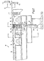
- FIG. lA, 2 and 3 an approach table 10 is shown leading to a bar shear 12.
- the bar shear is of a conventional design employing upper and lower shear knives 14a, 14b.
- the shear knives have grooves 16 spaced to provide a pitch nPk".
- the approach table 10 is also of generally conventional design with driven table rollers 18 establishing a support level "L", and with fixed table plates 20 spanning the gaps between the table rollers.
- a standard disappearing stop 22 extends transversely across the approach table at a location immediately upstream from the shear 12.
- the stop is vertically adjustable by conventional means (not shown) between a lowered position beneath the table support level L and a raised position above the level L as shown by the dot-dash lines in Figure 2.
- a separating device generally indicated at 24 is located in advance of the disappearing stop 22.
- the separating device includes a carrier frame made up of a generally L-shaped plate 26, end plates 28, a stiffener bar 30 extending between end plates 28, and another guide bar 32 parallel to the stiffener bar and also extending between end plates 28.
- Arms 34 extend from the underside of plate 26 to a pivot shaft 36.
- Shaft 36 is parallel to bars 30 and 32, and is journalled for rotation in bearings 38 supported on the table substructure.
- a first piston-cylinder unit 40 has its cylinder 40a pivotally anchored as at 42 and its piston rod 40b pivotally connected as at 44 between ears 46 protruding from the underside of plate 26.
- a helical spring 48 is axially inserted on the stiffener bar 30.
- the relationship between the inside diameter of the spring and the outside diameter of the stiffener bar is such that the spring may be freely extended and contracted.
- the ends of the spring 48 are connected to collars 50 slidably mounted on the stiffener bar 30.
- the collars 30 have depending ears 52 which are fixed to elongated guide sleeves 54 slidably mounted on the guide bar 32.
- the carrier frame also carries a pair of second piston-cylinder units 56 having their cylinders 56a pivotally connected as at 58 to a central bracket 60 on plate 26.
- the piston rods 56b of these units are pivotally connected as at 62 to the lower ends of the depending ears 52.
- one or more sets of centering arms 64 are provided. These arms are pivotable by any convenient known means (not shown) between closed positions as shown in Figures lA and 1B and open positions as shown in Figures 1C and 1D.
- rods 66 arranged in side-by-side relationship in a batch are being conveyed longitudinally along the approach table 10 in the direction indicated by arrow 68.
- the piston-cylinder unit 40 has been adjusted to drop the carrier frame, thereby placing the helical spring 48 in a lowered position beneath the support level L of the approach table.
- the piston rods 56b of the piston-cylinder units are retracted, and the helical spring 48 is in a contracted state.
- the disappearing stop 22 is in the raised position, and the centering arms 64 are closed.
- FIG. 1B A subsequent operational stage is shown in Figure 1B, where the rods 66 have come to rest with their front ends aligned against stop 22.
- the closed centering arms 64 have packed the rods laterally, causing the batch to be centred on the table 10.
- the stop 22 is dropped and the rods are advanced until the front ends are between the stop and the shear knives 14a, 14b.
- the stop 22 is then raised again, and the rods are advanced until the rod front end extends just beyond the shear knives.
- the piston-cylinder unit 40 is operated to elevate the carrier frame, placing the spring 48 in its raised position.
- the stop 22 is then fully retracted, and the rods are deposited on the spring as shown in Figures 1C, 2 and 3.
- the centering arms 64 are then opened.
- the rods 66 remain tightly packed on the spring 48.
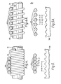
- the pitch P b of the rods is at a minimum and does not match the pitch P k of the grooves in the shear knives.
- FIG. 1D The next operational stage is shown in Figure 1D.
- the pistons 56b of the piston-cylinder units 56 have been extended to stretch the spring 48.
- the spring 58 when the spring 58 is stretched, its coils separate, causing the rods 66 to separate also.
- the spring is stretched until, as shown in Figure 5A, the pitch P b of the rods substantially matches the pitch P k of the grooves in the shear knives 14a, 14b.
- the piston-cylinder unit 40 is again actuated to lower the spring 48, thus causing the rods to drop into respective grooves 16 in the lower shear knife 14b.
- the shearing operation may then continue in the conventional manner.
- the present invention provides a simple yet highly effective means of laterally separating elongate elements.
- the invention is particularly suited for, although not limited in use to, the separation of rods or bars preliminary to a batch shearing operation by a shear of the type having grooved knives.
- rods or bars of different sizes and cross sections can be spread to any desired pitch. If the desired bar pitch is not achieved with one full extension of the spring, the separating operation can be repeated.
- the present invention also makes it possible to automate a separating operation, or in the alternative to manually control the separation operation from a remote location, which is particularly advantageous in rod or bar mills because of the high temperature of the product.
Landscapes
- Engineering & Computer Science (AREA)
- Mechanical Engineering (AREA)
- Accessories And Tools For Shearing Machines (AREA)
- Attitude Control For Articles On Conveyors (AREA)
- Metal Rolling (AREA)
- Combined Means For Separation Of Solids (AREA)
Applications Claiming Priority (2)
| Application Number | Priority Date | Filing Date | Title |
|---|---|---|---|
| US19342280A | 1980-10-03 | 1980-10-03 | |
| US193422 | 1980-10-03 |
Publications (2)
| Publication Number | Publication Date |
|---|---|
| EP0049621A2 true EP0049621A2 (fr) | 1982-04-14 |
| EP0049621A3 EP0049621A3 (fr) | 1982-06-30 |
Family
ID=22713568
Family Applications (1)
| Application Number | Title | Priority Date | Filing Date |
|---|---|---|---|
| EP81304575A Withdrawn EP0049621A3 (fr) | 1980-10-03 | 1981-10-02 | Séparation des bâtons ou barres dans des laminoirs |
Country Status (2)
| Country | Link |
|---|---|
| EP (1) | EP0049621A3 (fr) |
| JP (1) | JPS6031607B2 (fr) |
Cited By (3)
| Publication number | Priority date | Publication date | Assignee | Title |
|---|---|---|---|---|
| DE3618849A1 (de) * | 1986-06-04 | 1987-12-10 | Schloemann Siemag Ag | Verfahren und vorrichtung zur stoerungsfreien foerderung von profilen |
| FR2605537A1 (fr) * | 1986-10-23 | 1988-04-29 | Unimetall Sa | Procede et dispositif de repartition automatique de barres metalliques en nappe dans les crans de cisaille |
| CN119634821A (zh) * | 2024-12-02 | 2025-03-18 | 朗贤轻量化科技(安庆)有限公司 | 一种焊接金属波纹管的波片落料装置 |
Families Citing this family (1)
| Publication number | Priority date | Publication date | Assignee | Title |
|---|---|---|---|---|
| JPH0619771U (ja) * | 1992-04-20 | 1994-03-15 | 利光 森 | ゴルフ練習器 |
Family Cites Families (8)
| Publication number | Priority date | Publication date | Assignee | Title |
|---|---|---|---|---|
| US2180075A (en) * | 1938-05-20 | 1939-11-14 | Earl B Stout | Rail spacing apparatus |
| US2843249A (en) * | 1954-12-29 | 1958-07-15 | United Eng Foundry Co | Apparatus for spacing workpieces |
| US2955697A (en) * | 1957-01-02 | 1960-10-11 | Baker Perkins Ltd | Apparatus for guiding moving articles |
| US3209890A (en) * | 1962-10-18 | 1965-10-05 | Thomas R Miles | Feeding apparatus |
| GB1075570A (en) * | 1965-05-28 | 1967-07-12 | Moeller & Neumann Verwalt Ges | Apparatus for spreading apart a layer of adjacent rolled products |
| GB1572491A (en) * | 1977-01-28 | 1980-07-30 | Davy Loewy Ltd | Conveying equipment |
| US4098393A (en) * | 1977-04-22 | 1978-07-04 | Morgan Construction Company | Apparatus for laterally separating elongated magnetic elements |
| DD140658A1 (de) * | 1978-12-13 | 1980-03-19 | Guenter Estenfelder | Vorrichtung zum distanzieren von walzstablagen |
-
1981
- 1981-10-02 EP EP81304575A patent/EP0049621A3/fr not_active Withdrawn
- 1981-10-03 JP JP15695681A patent/JPS6031607B2/ja not_active Expired
Cited By (3)
| Publication number | Priority date | Publication date | Assignee | Title |
|---|---|---|---|---|
| DE3618849A1 (de) * | 1986-06-04 | 1987-12-10 | Schloemann Siemag Ag | Verfahren und vorrichtung zur stoerungsfreien foerderung von profilen |
| FR2605537A1 (fr) * | 1986-10-23 | 1988-04-29 | Unimetall Sa | Procede et dispositif de repartition automatique de barres metalliques en nappe dans les crans de cisaille |
| CN119634821A (zh) * | 2024-12-02 | 2025-03-18 | 朗贤轻量化科技(安庆)有限公司 | 一种焊接金属波纹管的波片落料装置 |
Also Published As
| Publication number | Publication date |
|---|---|
| JPS6031607B2 (ja) | 1985-07-23 |
| JPS5796720A (en) | 1982-06-16 |
| EP0049621A3 (fr) | 1982-06-30 |
Similar Documents
| Publication | Publication Date | Title |
|---|---|---|
| EP2377631A2 (fr) | Procédé et installation de tri et de pliage de tiges en acier et fils d'acier | |
| EP0773902B1 (fr) | Dispositif permettant d'enlever une pile de produits plats d'un point de groupage | |
| WO1991004113A1 (fr) | Dispositif de pliage de barres en acier afin de façonner des elements d'armatures en beton | |
| EP0564758A1 (fr) | Procédé et appareil pour diviser des plaques en verre en parties | |
| US4778165A (en) | Apparatus for folding and cutting web stacks | |
| US4873901A (en) | Apparatus for cutting and stripping insulation from wire segments having different gauge conductors | |
| DE1527878A1 (de) | Vorrichtung zur Beseitung des Haltebandes bei einem Bund | |
| EP0049621A2 (fr) | Séparation des bâtons ou barres dans des laminoirs | |
| EP0010597B1 (fr) | Canal d'alimentation pour barres et tubes | |
| DE2508745A1 (de) | Vorrichtung zum aufstauen vereinzelt vorgeschobener papierboegen zu stapeln und zum weitertransportieren dieser stapel | |
| EP0699395B1 (fr) | Dispositif pour la coupe en tranches de ballots | |
| CA2222353C (fr) | Palette a tige receptrice de bobines pour fabriquer des bobines deux fois moins lourdes | |
| DE2425463C2 (de) | Arbeitsverfahren zur Weiterbearbeitung von Profilstahl im Anschluß an eine Feinstahlwalzstraße und Anordnung zur Durchführung des Verfahrens | |
| DE69417648T2 (de) | Vorrichtung zum Wiederfinden und Entladen von kurzen Stangen | |
| DE68915804T2 (de) | Verfahren und Vorrichtung zum Herstellen einer gebogenen Glasscheibe. | |
| EP0401162A1 (fr) | Machine de peignage | |
| DE2741534C2 (de) | Verfahren zum Herstellen von Schraubenfedern mit ösen aus Draht und Maschine zur Durchführung des Verfahrens | |
| DE4134361A1 (de) | Wickelmaschine zum aufwickeln einer warenbahn, insbesondere einer papierbahn | |
| CN207239009U (zh) | 一种钢丝剪切装置 | |
| US3850204A (en) | Product handling apparatus | |
| DE2547114A1 (de) | Verfahren und vorrichtung zum ueberfuehren von staeben von einer streckbank zu einem foerderer | |
| DE2212944C3 (de) | Verfahren und Vorrichtung zur Bildung von Walzdrahtbunden | |
| DE10262028A1 (de) | Vorrichtung und Verfahren zur Verpackung von Gebinden, insbesondere Flaschengebinden | |
| US4436471A (en) | Method and apparatus for stacking for bars and the like | |
| DE643441C (de) | Geneigtes Kuehlbett fuer Walzwerke |
Legal Events
| Date | Code | Title | Description |
|---|---|---|---|
| PUAI | Public reference made under article 153(3) epc to a published international application that has entered the european phase |
Free format text: ORIGINAL CODE: 0009012 |
|
| AK | Designated contracting states |
Designated state(s): AT BE DE FR GB IT LU NL SE |
|
| PUAL | Search report despatched |
Free format text: ORIGINAL CODE: 0009013 |
|
| RHK1 | Main classification (correction) |
Ipc: B65G 47/26 |
|
| AK | Designated contracting states |
Designated state(s): AT BE DE FR GB IT LU NL SE |
|
| STAA | Information on the status of an ep patent application or granted ep patent |
Free format text: STATUS: THE APPLICATION IS DEEMED TO BE WITHDRAWN |
|
| 18D | Application deemed to be withdrawn |
Effective date: 19830609 |
|
| RIN1 | Information on inventor provided before grant (corrected) |
Inventor name: KLUSMIER, KENNETH |