EP0049880A1 - Système de coffrage pour la coulée de planchers nervurés en béton - Google Patents
Système de coffrage pour la coulée de planchers nervurés en béton Download PDFInfo
- Publication number
- EP0049880A1 EP0049880A1 EP81108151A EP81108151A EP0049880A1 EP 0049880 A1 EP0049880 A1 EP 0049880A1 EP 81108151 A EP81108151 A EP 81108151A EP 81108151 A EP81108151 A EP 81108151A EP 0049880 A1 EP0049880 A1 EP 0049880A1
- Authority
- EP
- European Patent Office
- Prior art keywords
- formwork
- ceiling
- elements
- yoke
- formwork according
- Prior art date
- Legal status (The legal status is an assumption and is not a legal conclusion. Google has not performed a legal analysis and makes no representation as to the accuracy of the status listed.)
- Granted
Links
- 238000009416 shuttering Methods 0.000 title claims abstract description 16
- 238000009415 formwork Methods 0.000 claims description 735
- 239000000725 suspension Substances 0.000 claims description 10
- 239000000969 carrier Substances 0.000 claims description 3
- 230000000149 penetrating effect Effects 0.000 claims description 3
- 229910000679 solder Inorganic materials 0.000 claims description 2
- 239000012528 membrane Substances 0.000 abstract 2
- 230000008901 benefit Effects 0.000 description 14
- 238000010276 construction Methods 0.000 description 6
- 229910052751 metal Inorganic materials 0.000 description 5
- 239000002184 metal Substances 0.000 description 5
- 125000006850 spacer group Chemical group 0.000 description 5
- 238000005520 cutting process Methods 0.000 description 4
- 238000006073 displacement reaction Methods 0.000 description 4
- 229910052782 aluminium Inorganic materials 0.000 description 2
- XAGFODPZIPBFFR-UHFFFAOYSA-N aluminium Chemical compound [Al] XAGFODPZIPBFFR-UHFFFAOYSA-N 0.000 description 2
- 238000011161 development Methods 0.000 description 2
- 230000002349 favourable effect Effects 0.000 description 2
- 230000005484 gravity Effects 0.000 description 2
- 238000003780 insertion Methods 0.000 description 2
- 230000037431 insertion Effects 0.000 description 2
- 238000009434 installation Methods 0.000 description 2
- 238000004519 manufacturing process Methods 0.000 description 2
- 238000000034 method Methods 0.000 description 2
- 239000011120 plywood Substances 0.000 description 2
- 230000008569 process Effects 0.000 description 2
- 230000002787 reinforcement Effects 0.000 description 2
- 230000003068 static effect Effects 0.000 description 2
- 229910000831 Steel Inorganic materials 0.000 description 1
- RTAQQCXQSZGOHL-UHFFFAOYSA-N Titanium Chemical compound [Ti] RTAQQCXQSZGOHL-UHFFFAOYSA-N 0.000 description 1
- 230000008859 change Effects 0.000 description 1
- 238000012937 correction Methods 0.000 description 1
- 238000010586 diagram Methods 0.000 description 1
- 230000004069 differentiation Effects 0.000 description 1
- 230000000694 effects Effects 0.000 description 1
- 239000007788 liquid Substances 0.000 description 1
- 238000003801 milling Methods 0.000 description 1
- 230000004048 modification Effects 0.000 description 1
- 238000012986 modification Methods 0.000 description 1
- 230000036316 preload Effects 0.000 description 1
- 238000003825 pressing Methods 0.000 description 1
- 230000008439 repair process Effects 0.000 description 1
- 230000000284 resting effect Effects 0.000 description 1
- 239000010959 steel Substances 0.000 description 1
- 239000010936 titanium Substances 0.000 description 1
- 229910052719 titanium Inorganic materials 0.000 description 1
- 239000002023 wood Substances 0.000 description 1
Images


Classifications
-
- E—FIXED CONSTRUCTIONS
- E04—BUILDING
- E04G—SCAFFOLDING; FORMS; SHUTTERING; BUILDING IMPLEMENTS OR AIDS, OR THEIR USE; HANDLING BUILDING MATERIALS ON THE SITE; REPAIRING, BREAKING-UP OR OTHER WORK ON EXISTING BUILDINGS
- E04G11/00—Forms, shutterings, or falsework for making walls, floors, ceilings, or roofs
- E04G11/36—Forms, shutterings, or falsework for making walls, floors, ceilings, or roofs for floors, ceilings, or roofs of plane or curved surfaces end formpanels for floor shutterings
- E04G11/40—Forms, shutterings, or falsework for making walls, floors, ceilings, or roofs for floors, ceilings, or roofs of plane or curved surfaces end formpanels for floor shutterings for coffered or ribbed ceilings
- E04G11/46—Forms, shutterings, or falsework for making walls, floors, ceilings, or roofs for floors, ceilings, or roofs of plane or curved surfaces end formpanels for floor shutterings for coffered or ribbed ceilings of hat-like or trough-like shape encasing a rib or the section between two ribs or encasing one rib and its adjacent flat floor or ceiling section
-
- E—FIXED CONSTRUCTIONS
- E04—BUILDING
- E04G—SCAFFOLDING; FORMS; SHUTTERING; BUILDING IMPLEMENTS OR AIDS, OR THEIR USE; HANDLING BUILDING MATERIALS ON THE SITE; REPAIRING, BREAKING-UP OR OTHER WORK ON EXISTING BUILDINGS
- E04G13/00—Falsework, forms, or shutterings for particular parts of buildings, e.g. stairs, steps, cornices, balconies foundations, sills
- E04G13/04—Falsework, forms, or shutterings for particular parts of buildings, e.g. stairs, steps, cornices, balconies foundations, sills for lintels, beams, or transoms to be encased separately; Special tying or clamping means therefor
Definitions
- the invention relates to a system formwork for a concrete ceiling having a joist with side formwork elements for the side surfaces of the joist, the formwork skin of which is attached to beams running transversely to the longitudinal axis of the joist, with bottom formwork elements for the bottom surface of the joist, which have at least one formwork skin, and with Devices that connect the side formwork elements together.
- This beam formwork which is always rigid at the place of use, must fit very precisely into the ceiling formwork; it is hardly possible to clamp it together with the ceiling formwork to seal joints.
- the production of this joist formwork and its insertion into the slab formwork requires a considerable amount of work.
- This girder formwork is also very heavy and can no longer be switched on and off by hand.
- the invention has for its object to develop a joist formwork that is not only easily installed in the slab formwork, but can also be easily expanded after concreting, which is handy and still accurate and true to size.
- a particular advantage of the invention is that the pivoting suspension of the side formwork elements on the slab formwork allows the beam formwork to be assembled at the place of use and therefore the individual parts of the formwork can be brought to the place of use in handy sizes.
- the shells of the joist is very simple, because d 'l rch effortless swiveling of the side formwork elements the correct dimensions can be easily produced, at least in the lower area of the beam formwork.
- the formwork so difficult in the known beam formwork can also be accomplished very easily in the formwork according to the invention, because after loosening the fastening means holding the formwork together at its lower end, the side formwork elements only have to be pivoted apart again in order to be able to remove them.
- a side formwork element can be chosen smaller than the distance between two adjacent supports supporting the ceiling formwork in the ceiling formwork according to the invention due to the lack of the longitudinal beam necessary in the known beam formwork, if such a large swivel angle is required to remove the side formwork elements, the freely hanging legs of the ceiling formwork elements can be pivoted into the space between two ceiling supports. If a side shell element is located in the area of a ceiling prop, it can be pushed in its place after removal of the adjacent side shell element and then also through Swing into the space between two floor props can be removed. This is not possible with the known beam formwork according to the Heilwagen, because there the supports engage directly on the side member, a distance between the supports larger than the length of the side member is not possible, because then the support of a side formwork element would no longer be supported.
- the side formwork elements are held in the yoke after lowering and in the laterally moved position in the known joist formwork, the side formwork elements cannot be easily detached from the clamp in the known formwork.
- the formwork according to the invention it is possible first to remove the bottom of the girder formwork and only then to remove the hanging side formwork elements individually, so that individual elements of the girder formwork which can be easily transported by hand can be removed without the need for to support certain parts additionally when striking and without the risk that unsecured parts accidentally fall down when stripping.
- the side formwork element has its pivotable suspension on the Dek kenschalung a leg forming a portion of the slab formwork, which has projections and / or bearing shells, which cooperates with bearing shells and / or projections of a part of the slab formwork, so that these interlocking parts define and fix the pivot axis.
- This embodiment of the invention can be further developed in such a way that the mutually cooperating joint parts consist of interlocking hook-like parts; in particular, the means arranged on the ceiling formwork for pivoting suspension of the side formwork element can have hook-like parts in cross section.
- the pivot axis can either run in the immediate vicinity of the end of the horizontal leg facing away from the beam or at a distance from this end. In embodiments of the invention, the pivot axis can run in or in the immediate vicinity of the formwork skin of the horizontal leg or at a distance from the formwork skin of the ceiling formwork, for example on the lower surface of the horizontal leg and, for example, also below the end of the horizontal leg facing away from the beam.
- the pivot axis extends in the formwork plane or in the immediate vicinity of the formwork plane and at the end of the horizontal leg, then when the formwork is removed after loosening the fastening means holding the lower ends of the vertical legs of the side formwork element, they can be pivoted slightly outwards. No stripping play is theoretically required for this if the swivel axis runs exactly in the formwork plane. In practice, however, this is difficult and in practice, the interlocking parts forming the swivel axis usually have some play.
- the stripping play required must be greater, the greater the distance between the pivot axis and the formwork skin of the horizontal leg. Measures for obtaining such a stripping game are not necessary, however, if, according to one embodiment of the invention, where the horizontal leg and the vertical leg of the side formwork element meet, the side formwork element is not delimited by an edge which is rectangular in cross section, but by a circular arc section whose radius intersects the swivel axis.
- a haunch is provided at this point, the edges of which lie with the horizontal formwork surface and the vertical formwork surface approximately on an arc around the pivot axis.
- the inclined surface of the haunch can also extend over the Extend the line that contains the base of a plumb bob fallen from the swivel axis onto the vertical formwork surface and extend over the entire height of the vertical formwork.
- the inclination of the haunch surface with respect to the vertical surface is extremely small if the pivot axis runs at the lower edge of the end surface at the end of the horizontal leg.
- the greatest thickness of the horizontal leg of the side formwork element forming the slab formwork section is so much smaller than the drop height of the Fallko p fes that when striking these horizontal legs it can be pushed over the edge of the formwork surface of the slab formwork.
- the length of this leg can then be chosen so that the side formwork element can be pivoted so far about the upper edge of the end face of the ceiling formwork element facing the beam that the horizontal section of the side formwork element between the edge of the ceiling formwork and the beam can be removed from the ceiling formwork .
- the entire slab formwork When striking, the entire slab formwork can be lowered in a manner known per se, first by lowering the falling heads of the slab formwork, then the side formwork elements, because they hang in the slab formwork, that is, as a rule, are suspended in a hook open at the top be lifted. Then the horizontal leg is pushed over the adjacent ceiling formwork element and then the lower end of the side formwork element is pivoted far outwards.
- the stripping of the beam formwork according to the invention is particularly simple and effortless.
- the angular shape of the side formwork element and its suspension at the outer end of the horizontal leg has the advantage that the vertical leg of the side formwork element hangs obliquely outwards after hanging in the ceiling formwork, i.e. the lower end of the side formwork elements arranged opposite one another has a greater distance than theirs top end.
- these ends endeavor to lie against the legs of the clamp engaging below and when the clamp is tensioned, that is to say when the side formwork elements pivot inwards, in contact with the lower ones Stay overlapping ferrule legs.
- the side formwork element can be suspended from a beam of the ceiling formwork, but it can also be partially suspended directly from the drop head of a ceiling support.
- the pivoting movement of the side formwork elements directed towards the beam is limited by a stop in the position in which the side formwork element adjoins the ceiling formwork zenden ceiling formwork element forms the intended angle.
- a stop results in the desired angle, usually this angle will be a right angle, when the vertical legs of the side formwork elements are clamped together.
- the stop limiting this pivoting movement can be attached to a part that does not belong to the side formwork element or ceiling formwork element.
- the aforementioned embodiment can, however, be further developed in such a way that this stop between the side formwork element and the ceiling formwork element is effective, so that when the desired angular position is reached, the previously articulated connection behaves like a rigid angular connection by removing the pivoting possibility.
- the side formwork element carries out a translational movement in the direction of the beam, in which the ceiling formwork element, which is now rigidly connected via the pivot axis, is supported, supported by formwork supports.
- the slab formwork element can take part in this translational movement because the slab formwork is "softly" supported in this direction, the supports for the slab formwork are slightly inclined bPi this small correction movement, without this having any recognizable disadvantages.
- a stop limiting the pivoting movement is formed by the contact of the side face of the ceiling beam on a bar connecting the webs of the side formwork element and forming the end face of its horizontal leg.
- the pivotable suspension of the side formwork element on the slab formwork is designed so that this hinge connection absorbs the tensile forces that occur in the aforementioned case when the pivoting movement is blocked and transmits them to the slab formwork.
- the side formwork element is suspended from a support of the ceiling formwork (ceiling support) and the pivot axis of the pivoting movement is at a distance from the horizontal formwork surface
- the end faces of surfaces of the ceiling formwork and end faces of the articulation axis located above horizontal section of the side shutter element are given a course in which they come to rest against each other to limit the inward pivoting movement of the side shutter element and thus form the stop limiting this pivoting movement in this pivoting direction.
- embodiments of the invention can be designed such that the ceiling support on its side surface in Distance from the formwork surface has open hooks in which the side formwork element engages.
- the leg of the side formwork element forming the slab formwork section can have on its underside a downwardly projecting strip which engages in the hook base.
- This embodiment of the invention can be further developed in such a way that the bar is connected to the carrier of the side formwork element by webs running transversely to the longitudinal axis of the beam, these struts preferably being formed by angling at the upper end of the carrier, and that the webs have one at their lower edge Have recess for receiving the hooks arranged on the slab formwork beam.
- This recess can be followed by a further, less deep recess, which then forms part of the articulated connection of the side formwork element to the ceiling formwork if the ceiling formwork element adjacent to the side formwork element has no hooks, but rather the horizontal leg of the side formwork element has to be placed on a strip .
- the webs angled from the carrier of the side formwork element carry the formwork skin of its slab formwork section and the ends of the webs of adjacent beams are connected to one another by a strip, preferably the webs are connected to one another in pairs by the strip.
- This embodiment of the invention can be further developed in such a way that the distance between the hooks on the longitudinal ceiling beam is smaller than the length of the bar that is supported in the hook base.
- the side formwork elements can be moved along the formwork plane as required and do not have to be hung in a position determined by the hooks.
- the bottom formwork elements are longer than the side formwork elements. Since the lower ends of the side formwork elements are tensioned against the end faces of the bottom formwork elements, this ensures that the bottom formwork elements align the side formwork elements in the longitudinal direction and that this alignment is transmitted to the slab formwork via the rigid joints when the clamp is tensioned.
- the horizontal and / or vertical formwork skin sections can be fastened to the side formwork element after it has been suspended. Since the joist formwork according to the invention is usually assembled at the place of use by first hanging the side formwork elements and then attaching the formwork element and pressing the lower ends of the side formwork elements, it is advantageous if the individual parts to be transported to the place of use are as light as possible , which can only be achieved by attaching the formlining after the side formwork elements have been attached.
- the girder formwork at the lower end of the side formwork elements can be closed in various ways in the formwork according to the invention. In one embodiment of the invention, this is done with a device which uses the known principle of the beam clamps at night and in which the yoke of the clamp can be fastened to the Sellenschaliata in a manner which is known per se is.
- This embodiment can be further developed in such a way that, according to the invention, the yoke of the clamp can be brought up from below into its fastening position on the hanging side formwork elements, and that the effective length of the yoke of the clamp can be adjusted.
- the clamp can also be easily attached from below to the side formwork elements hanging from the slab formwork.
- the lower ends of the side formwork elements can be swiveled inwards at the same time as the yoke of the clamp is adjusted.
- the adjustability of the ferrule yoke to its effective length can be achieved in various ways.
- two displaceable sections are arranged on a yoke rod. This has the advantage that the two sections can be designed identically.
- the sections can be guided with a relatively large amount of lateral play on the yoke, so that the displacement movement is insensitive to lateral tilting.
- the sections can be secured in their mutual position by means of aligned holes arranged in both sections and pins inserted into them, or also by a tension rod inserted into the hollow profile of the yoke and extending in the yoke axis with tensioning means arranged at its ends.
- the sections can be determined in their mutual position by wedges which are driven in after the correct yoke length has been set.
- the bottom form element is arranged between the lower ends of the side form elements, so that these ends are clamped against the end faces of the bottom form element when the clamp is tensioned. This not only has the advantage that the joint between the lower formwork element and the side formwork element is tight and even with one Preload can be tensioned, which corresponds to the pressure of the concrete during pouring and shaking, but also that the distance between the lower ends of the side formwork elements does not have to be specified in particular, but results automatically by contact with the bottom formwork element.
- the height-selectable fastening of the beam clamp can be done in various ways, it is essential that it is brought up to the beam formwork from below and can be tensioned in this position.
- the yoke of the clamp can be attached directly to supports of the side formwork elements, in which case the supports of these side formwork elements are extended beyond the lower end of the formwork skin, so that these supports form the clamp legs directly, or else clamp legs can be rigidly attached to the displaceable sections of the yoke be, which in turn can be fastened selectively in height to the back of the side formwork elements, these legs rigidly connected to the yoke not only taking on the function of fastening the clamps at a certain altitude, but also the function of determining the side formwork element in one Angular position to be fixed conditions, so that these clamp legs when tensioning the clamp also have the effect that the inward pivoting movement of the side formwork elements is limited about the pivot axis and the ceiling formwork is pulled along with further tensioning of the clamp.
- embodiments of the invention can be designed such that the carrier of the side shell. have teeth protruding outwards at right angles to the longitudinal beam axis, which are used to select the fastening height of the lower formwork element.
- the distance between the teeth can expediently be between 2 and 3 cm. This has the advantage that the position of a clamp hooked into a wrong tooth deviates relatively strongly from the position of the other clamps, so that this is immediately apparent.
- strips extending transversely to the yoke are attached to the mutually displaceable sections of the yoke, which are suitable for engaging in the tooth bases between the teeth of the wearer.
- fastening for fastening the clamp which can be selected in height, can also be selected, for example perforated rails, in the holes of which either the clamp legs or the clamp yoke are fastened directly with the aid of bolts.
- the strip which engages in the tooth bases can be arranged above or below the ferrule yoke, but only below if the carriers are extended beyond the lower edge of the formlining of the side formwork element and there support teeth.
- the two sections of the yoke have stops arranged at a distance above the formlining of the lower formwork element at a rigid angle to the longitudinal axis of the yoke, which are used for bearing against the side of the side achal element facing away from the formwork skin. These stops are arranged so that the side formwork element is at the desired angle - normally a right angle - when the clamp is tensioned.
- the distance between the two formwork elements is determined by the width of the formwork skin of the bottom formwork element.
- the upper stop located on the clamp legs pulls the side formwork element with it and possibly also the ceiling formwork with the supports, since the supports are not rigidly anchored at their upper end attached to the ceiling formwork.
- the contact of the lower end of the side formwork element on the end face of the formwork skin of the lower formwork element is limited, the inward pivoting movement of the side formwork element both at the connection of the side formwork element to the ceiling formwork and by this stop of the side formwork element on the bottom formwork element.
- these stops can also be formed by a transversely extending strip and the distance of the stops from the lower end of the formlining of the side formwork element can be approximately one third of the height of the side formwork element.
- stops acting on the rear of the side formwork elements at different heights can be provided on clamp sections.
- the stops can be arranged in such a way that one stop acts above the level of the formlining of the lower formwork element and the other stop below this level on the rear side of the side formwork element.
- the beam formwork can be clamped together using individual clamps.
- two mutually adjacent clamps are always rigidly connected to one another in pairs, for example by the bar engaging in the tooth bases and / or by the bar which is at a distance above the yoke and transversely to the longitudinal direction of the yoke at the rear of the side formwork element stop coming to rest.
- the strips are always longer than the distance between two beams of the side formwork element, it is not necessary that the side formwork elements of the formworks lying opposite one another lie exactly opposite one another, rather the position of the side formwork element is along the side surface of the beam completely regardless of where the opposite side formwork element is located. This is particularly advantageous if, due to any protrusions projecting laterally from the beam, the continuously continuous side surfaces of the beam are not of the same length on both sides.
- the formwork element consists of squared timbers arranged on the ferrule yokes and a formwork skin loosely placed over them.
- the squared timbers can also be placed loosely on the Zwingenjoch or can be fastened on the Zwingenjoch.
- the under-beam formwork according to the invention is particularly easy to use.
- this has the advantage that the squared timbers do not interfere if the girder is so narrow that it is binding with the side surfaces of a concrete support, that is to say the side formwork elements are moved so close together that they abut the side surfaces of a concrete support.
- the bottom formwork elements can have only one formlining alone, or can also have additional supports that support the formwork facing. It is not necessary for the bottom formwork elements to be supported on the yoke of the clamp. Rather, in one embodiment of the invention support strips nailed to the inner surface of the formlining of the side formwork elements, onto which the formwork skin of the bottom formwork element or the entire bottom formwork element is then placed when the side formwork elements are pivoted in.
- the particular advantage of this embodiment of the invention is that the width of the girder can be adjusted by cutting the lower formlining, which extends over several lengths of the side formwork elements, and by automatically aligning the side formwork elements to this dimension, the other dimensions are exactly maintained.
- the vertical dimensions of the girder formwork can also be easily adjusted by releasably attaching the clamp to the teeth of the side formwork elements at a selectable height, with a dimension between the dimensions of the tooth being set by selecting the height of the squared timbers resting on the yokes or corresponding intermediate layers can be.
- this projection can be formed by a plate arranged at the lower end of the extension of the carrier, which plate also forms a base plate for the side formwork element.
- the lower formwork shuttering at the lower end of the side formwork elements does not take place by means of a beam clamp surrounding the side formwork elements, but the side formwork elements are detachably connected to one another by floor brackets which run from the inner surface of one side formwork element to the inner surface of the other side formwork element and at least the fastening means between one end of the floor support and the adjacent side formwork element can be released when stripping.
- the girder formwork can be dismantled into easily transportable individual parts when stripping. First of all, the connection between one end of the floor beams and the adjacent side formwork element is released and then the side formwork elements are pivoted outwards, if necessary after lowering the ceiling formwork.
- the formwork skin of the lower formwork element which is supported on the floor beams, and possibly also the longitudinal beams arranged between this formwork skin and the floor beams are removed.
- the side formwork elements are then unhooked and removed; if necessary, the base supports, which are still attached at one end to a side part, are also removed beforehand.
- essential parts of the formwork are namely the side formwork elements, because of their hanging arrangement during assembly and disassembly of the formwork.
- holes penetrating the formlining are also provided in order to accommodate the fastening means connecting the floor form with the side formwork element.
- This has the advantage that the formlining for the side surfaces of the beam can be very far down, namely in one embodiment of the invention to the depth that corresponds to a height of the beam for which the formwork is intended to the maximum.
- the holes in the formlining that are not required are closed with plugs.
- the advantage of this embodiment is that not only the same side formwork elements can always be used when formwork of different high beams, but also the adjustment of the formlining to the respective height of the beam is no longer necessary because the lower formwork element, i.e. the formwork floor in any Height between the two side formwork elements can be fixed without the formwork skin projecting further downward hindering the fastening of the formwork floor.
- the formlining can be permanently attached to support-forming metal profiles, e.g. B. riveted.
- the formlining is so far down that its lower edge is at the upper edge of a bottom bracket attached to the legs in its lowermost position.
- the floor supports can be attached to the side formwork elements in various ways.
- the floor supports have a plate on their end faces which extends over a plurality of holes in the formlining. A row of holes is provided in this plate, the holes of which are at a distance from one another which is smaller than the distance of the holes in the formwork skin. This allows the height of the formwork floor to be selected in very small steps.
- the floor supports can also be designed in a wide variety of ways.
- Floor supports which according to one embodiment of the invention are formed by two upright sheets, have proven to be particularly advantageous are, which are attached to each other offset, the sheets have at least two rows of holes arranged one above the other and the holes of the one sheet have a distance from each other that differs somewhat from the distance of the holes of the other sheet. This allows the length of the shelf supports to be adjusted easily and also in very small steps.
- This embodiment can be further developed such that the sheets are reinforced by folding their edges.
- Such floor supports are extremely stable. Since the holes in the formwork skin are provided in the area of the vertical support legs of the side formwork elements and also put them through, when attaching a floor support, for example by only two wedge bolts or screws, a rigid structure is created, which also allows one to be attached to only one formwork element when formworking to support the bottom formwork containing the bottom girder at its projecting end with a support and then to attach the reinforcement of the girder to the bottom formwork element.
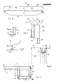
- the beam formwork shown in FIGS. 1 and 2 in the assembled state has two completely identical side formwork elements 1 and 2, which are spaced parallel to one another and between which a bottom formwork element is arranged, which is formed by squared timber 3 and a formwork skin section 5 supported by this is.
- the two side formwork elements 1 and 2 are held together by a double clamp 7, which is shown in the disassembled state in FIG. 7.
- the squared timbers 3 rest on long yoke sections 9 which are connected in one piece to the right part of the double clamp in FIGS. 1, 2 and 7 and which are in short yoke sections 10 of the left part of the double clamp in FIGS. 1, 2 and 7 introduced and secured against displacement by a wedge 12.
- the two side formwork elements 1 and 2 are pressed firmly against the formwork skin section 5 by the double clamp 7.
- the side formwork elements 1 and 2 have an upper horizontal leg 15, which carries a horizontal formwork skin section 16, which forms part of the slab formwork for the ceiling immediately adjacent to the beam.
- a vertical leg 17 runs at right angles to the horizontal leg 15 and carries a formwork skin 18 running in a vertical plane.
- the vertical leg 17 forms the side formwork for the beam to be produced. If the side surface of the beam is opposite the If the underside of the concrete ceiling is to enclose an angle deviating from a right angle and / or the underside of the ceiling is not to run horizontally, the angle between the legs 15 and 17 is chosen to be different from the exemplary embodiment.
- the vertical formwork sections 18 usually do not come into contact with the concrete at their lowermost end region because the formwork section 5 of the lower formwork element generally abuts the formwork surfaces of these formwork sections at a distance above the lower edge 20 of the vertical formwork sections 18.
- the vertical formlining section 18 is supported by spaced-apart, vertically extending supports 25 which have a recess open towards the formwork facing section 18, into which a wooden strip 27 is firmly inserted, which makes it possible to form the formwork facing section 18, which is formed by a plywood panel, to be fastened to the supports 25 by nailing, see FIG. 6.
- formwork boards can also be used. By removing or nailing the required number of formwork boards from e.g. 10 cm width the lower edge 20 of the formwork surface can be shifted slightly up or down.
- the side formwork elements 1 and 2 each have four supports 25.
- Two of the supports 25 each have a web 30 on their side surfaces 29 facing away from one another, perpendicular and transverse to the level of the formlining 18, and the ends of two of these webs 30 facing away from the formlining section 18 are connected to one another by a strip 32 running parallel to the formlining section 18 .
- the webs 30 and the strip 32 are made of a strong sheet metal poses.
- the top of the webs 30 and the strip 32 supports the horizontal formwork section 16, the surface 33 of the strip 32 facing away from the formwork section 18 being flush with the corresponding end face 34 of the horizontal formwork section 16.
- the underside formwork element i.e.
- the formwork sections 16 and 18 protrude beyond the foremost and rearmost supports 25 and the foremost and rearmost web 30, something which is shown in FIG left rear carrier 25 and the right front web 30 and can be seen in Fig. 5.
- This protrusion can be, for example, 10 cm.
- the strip 32 does not extend over the entire length of the side formwork elements shown in FIGS. 1 and 2, the formwork skin sections 16 and 18 each extend over the entire length of the side formwork elements 1, 2. They bridge the area between the two middle supports 25, which are not connected to one another by a strip 32.
- the formwork skin sections 18 do not extend to the lower end of the carrier 25.
- the carrier 25 have on their back a parallel to their longitudinal direction projecting ledge 38, which extends over the entire length of the carrier 25 and has teeth 39 produced in the lower half by cutting or milling, which thus transverse to the formwork plane of the Project formwork section 18 to the rear.
- the distance between the teeth 39 measured from the tooth base 40 to the tooth base is 25 mm in the exemplary embodiment.
- the shape of the teeth 39 is arbitrary within wide limits, it only has to be chosen so that the teeth provide sufficient support the double clamp 7 described in more detail below.
- a plate 42 is welded, which still projects beyond the height of the teeth 39 to the rear. This plate serves as additional security when installing the joist formwork, as will be described later, and it also allows the side formwork element 1, 2 in the position shown in FIG. 4 to be set up on a flat surface, which can be favorable immediately before the formwork work .
- FIG. 2 A favorable shape of the teeth 39 is shown in FIG. 2, in the remaining figures the toothing is only shown schematically.
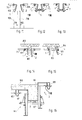
- the device shown in FIG. 7 is referred to as a double clamp 7 because it comprises two yokes, each having a long section 9 and a short section 10, whereas the simple clamp 43 according to FIG. 8 has only one such yoke.
- the yoke sections 9 and 10 are each formed by a square tube, the longer sections 9 can be inserted into the shorter sections 10 and displaced therein.
- the upward-facing side 45 is cut out.
- a bracket 46 is welded to the two side surfaces 47 and 48 of the short yoke section 10. This bracket 4t. interacts with the wedge 12 such that when Driving the wedge 12 in the illustration of FIG. 2 in the direction to the right, the long yoke section 9 can be clamped in any position in the short yoke section 10. Compare also Fig. 3.
- the two long yoke sections 9 of the part 7 'on the right in FIG. 7 are arranged parallel to one another at a distance and connected to one another by a bar 51 of essentially square cross-section welded to their underside, which is located at the right end region of the yoke sections 9 in FIG. 7 .
- a strip-like projection 52 pointing to the left in FIG. 7 is provided on the strip 51 and is designed such that it can penetrate the tooth base 40 between two teeth 39.
- spacer plates 53 are welded, which carry at their upper end a further bar 55 which runs parallel to the bar 51.
- the plane laid by the two long yoke sections 9 is perpendicular to the plane laid by the two strips 51 and 5%.
- This side formwork element 61 additionally has, at its end facing the viewer, a formwork section 62 running at right angles to the formwork level of the formwork section 16 and the formwork section 18, which are shorter here than in FIG. 1, each of which has an edge with the formwork sections 16 and 18 just mentioned 63 and 64 forms. If this additional formwork section 62 is not present, the side formwork element 61 can be used in the same way as the side formwork elements 1; if the further formwork section 62 is present, it is also suitable for formworking beams that meet at right angles, as will be explained later.
- FIG. 10 shows together with the upper right part of FIG. 2 a ceiling beam which is used in the formwork according to the exemplary embodiment.
- the ceiling support 65 consists of an aluminum hollow profile of the cross section visible in FIG. 2.
- the top 66 forms part of the formwork surface for the bottom of the concrete ceiling.
- This upper side 66 is adjoined by side surfaces 67 running at right angles to it and parallel to one another, which run obliquely towards one another from half the height of the profile and are provided with the reference number 68 there.
- Halfway up the profile of the ceiling support 65 are provided outwardly projecting strip-like projections 69 which extend over the entire length of the ceiling support 65 and which carry spaced apart upwardly projecting hook-like projections 70.
- the ceiling support 65 in each case has a cross bolt 71 which penetrates the cavity of the hollow profile and serves to drop the ceiling support 65 into a hook to mount.
- a very similar support to the described ceiling support and a matching drop head is in the patent application P 30 04 245.6. If necessary, further details can be found in the aforementioned patent application.
- the thickness of the strip 32 of the side formwork elements 1, 2, 61, measured perpendicular to the formwork plane of the formwork skin section 18, is so large that the underside of the strip 32 can rest on the strip-like projection 69 of the ceiling support 65.
- the hook-like projections 70 prevent the bar 32 from sliding off the ledge-like projection 69. So that the side formwork elements 1, 2, 61, regardless of the presence of the hook-like projections 70 at any point, the ceiling support 65 can be supported on its strip-like projection 69, the webs 30 are provided with a recess 75 adapted to the shape of the hook-like projection 70. This is followed by a further recess 76 of lesser height, which is designed in such a way that it allows the side formwork element to be supported on a strip-like carrier, as described as an extension profile in the above-mentioned patent application.
- FIGS. 11-13 The erection of the formwork for a beam is described with reference to FIGS. 11-13. It is assumed that the ceiling beam 65 supported on the left in FIG. 11 in its height required for concreting by a formwork support 101 is secured against displacement in the horizontal direction transversely to its longitudinal direction, for example by a ceiling formwork element 71 which is supported on the strip-shaped projection 69 on its left side and engages over the hooks 70. In contrast, the right-hand ceiling support 65 in FIG. 11 can still be shifted somewhat in the direction just described. The side formwork elements 1 and 2 are now attached to the ceiling beams 65 with their strips 32.
- the side formwork elements 1 and 2 pivot so that their lower ends face away from one another, as shown in FIG. 11.
- the mounting of the side formwork elements on the ceiling supports 65 is designed in such a way that this pivoting movement is possible, so the hook 70 in the configuration shown in FIG. 2 expediently does not reach to the upper end of the recess 75, so that the pivoting movement always around the lower edge the bar 32 takes place at its location on the strip-like projection 69.
- a double clamp 7 (or a clamp 43) is now prepared by plugging the two parts 7 'and 7 "together, the strips 65 being so far apart from one another that the double clamp is when the two lower ends of the side formwork elements 1 and 2 something can be moved towards one another by the craftsman, can be pushed over the plates 42 from below over the carrier 25, the clamp 7 being raised so far that the strip-like projections 52 into the area of the teeth 39 reach.
- the double clamp 7 is now raised until the long yoke sections 9 and the short yoke sections 10 abut the lower edge 20 of the vertical formwork skin sections 18 of the right and left side formwork elements; then, if necessary, the double clamp 7 is slightly lowered until the strip-like projections 52 can engage in the next tooth base 40 that can be reached.
- the squared timbers 3 are now placed on the long yoke sections 9, and a formlining section 5 is placed thereon, the width of which corresponds exactly to the width of the beam to be produced on the underside thereof, and the length of which can extend over a plurality of side formwork elements arranged one behind the other, as a result of which the Side formwork elements are additionally aligned so that their formwork skin sections are very precisely aligned with one another.
- the two parts of the double clamp 7 are now pushed further together, thereby moving the vertical formwork sections 18 with their lower region against the end faces of the formwork section 5 facing them, which form a stop through which the Distance of the side formwork elements 1 and 2 is set in its lower area.
- the ceiling beam 65 on the right in FIG. 11 is moved to the left because its hooks 70 engage behind the strip 32 of the side formwork element 2.
- the double clamp can be designed in this way that a prestress can easily be generated to counteract the pressure of the liquid concrete.
- the position in which the double clamp 7 is attached to the somewhat closer side formwork elements 2 is shown in FIG. 12, in FIG.
- FIG. 11 also shows a support made of concrete 78 for supporting the finished beam, the width of which can be seen in FIG. 11 corresponds exactly to the width of the beam to be produced in its lower region.
- the vertical formwork skin sections 18 of the two side formwork elements 1 and 2 lie flat in the area of the concrete support 78 on the upper edge area of their side walls 79 and 80.
- the height of the concrete support 78 is selected so that a formwork element 5 arranged in front of the concrete support 78 in the viewing direction of FIGS. 11-13 extends as far as that facing the viewer Side of the concrete column 78 can be pushed up and rests there.
- the distance of the lower end face 20 of these formwork sections from the formwork level of the formwork section 16 is selected so that in the hanging process described above, the double clamp 7 taking into account the thickness of the formwork section 5 and a predetermined height of the squared timbers 3 gives the desired height of the beam.
- a pivoting movement of the supports 25 from the position shown in FIG. 11 over the position shown in FIG. 13, in which the vertical formwork skin sections 18 run parallel to one another, is not in the exemplary embodiment possible because when the vertical position of the formwork section 18 is reached, the surface 33 of the strip 32 facing away from the formwork section 18 abuts the adjacent surface 67 of the ceiling support 65, so that these two abutting parts form cooperating stops and the bottom edge of the strip 32 does not deviate from that Can move back surface 67 because this is prevented by the hook 70. Therefore, even if the formwork section 5 of the bottom formwork element should be removed for any reason in the formwork in accordance with FIG. 13, the double clamp 7 is prevented from falling off.
- the side formwork elements 1, 2 are individually raised so that the underside of the horizontal leg 15 is in a plane above the top 16 of the ceiling beam, then the raised side formwork element is moved towards the ceiling beam, so that the horizontal Leg 15 is now above the top 66 of the ceiling support 65, as shown in Fig. 15 in the left part, and can now by a pivoting movement, which is indicated in Fig. 15 in the right part, the side formwork element down through the space between the Ceiling beams 65 and the beam 83 are removed, the edge 35 between the formwork sections 16 and 18 roughly describes a circular arc around the longitudinal axis of the ceiling beam.
- the length of the section 85 of the horizontal section projecting beyond the rear side of the strip 38 in a direction facing away from the formlining section 18 Leg 15 is dimensioned such that when the leg 15 is pushed over the formwork support 65, the formwork skin section 18 gains a sufficiently large distance from the side surface of the beam.
- FIG. 16 shows the formwork realized with the formwork according to the invention for an edge beam 87 which is located on the edge of a concrete ceiling 88.
- the two side formwork elements 111, 2 are not at the same height, rather that ceiling support 65, in which the side formwork element 2 on the right in FIG. 16 is suspended, is in one 16 is higher than the ceiling beam 65 on the left in FIG. 16.
- the upper area of the vertical formwork skin 18 of the side formwork element 2 thereby simultaneously forms the side formwork for the right end face of the concrete ceiling 88.
- the side formwork element 111 differs from the side formwork element 2 only in that Formwork skin section 18 'has a lower height than the formwork skin section 18 of the element 2, so that the' lower edge of the formwork skin section 18 'is approximately at the same height above the floor as in the case of the element 2.
- the difference in height to be realized with the side formwork elements shown between two through a clamp 7 interconnected side formwork elements is determined by the length of the toothing on the supports 25. In the exemplary embodiment, the maximum possible height difference between the two side formwork elements 111, 2 has almost been reached.
- a particular advantage of the formwork according to the invention is that the formwork can be assembled from individual parts at their final place of use, namely in the area of the beam to be produced, but it is also possible if this should be necessary for any reason, which in 1 and 2 shown fully assembled formwork to move as a whole.
- the formwork section 5 of the lower formwork element is located at a height above the bar 51 and below the bar 55, which, with its faces 88 and 89 facing the respectively adjacent support 25, bear against the bar 38 or the outwardly projecting end of the teeth 39 ,
- the side formwork elements 1, 2 can neither be sunk: one of these strips 51, 55 nor around the end face of the formlining section 5 lying against them ken and the arrangement shown in Figs. 1, 2 is therefore completely stable in itself without it having to be suspended from ceiling beams 65.
- the side formwork elements used to form the two side surfaces of a beam can be arranged without difficulty so that they are almost exactly opposite one another, as shown in FIG. 1.
- Such an arrangement of the side formwork elements is by no means necessary in this application. If a girder meets another girder at a right angle, an exactly opposite arrangement of the side formwork elements formworking the two side surfaces is generally not possible in the course of the continuous girder, as shown in FIG.
- FIG. 17 which shows a schematic plan view of the arrangement of side formwork elements for formworking a ceiling is, which has a long beam 91, which is supported in the region of its ends and its center by concrete supports 92, 93, 94, and in the region of the center and one end of the beam 91 has shorter beams 95 and 96 extending transversely thereto, the Ends are also supported by concrete supports 97 and 98 and are connected by a beam 99, which in turn runs parallel to the beam 91.
- Side formwork elements 1 are shown, which all have the same length, as well as shorter side formwork elements 1 ", which can be of different lengths.
- the course of the vertical formwork skin section 18 is denoted in each case by a thick line, and for those side formwork elements 1 ′′, the one perpendicular to formwork section 18 and vertically blue have formwork section 62 (Fig. 9), this formwork section also indicated by a thick line.
- the horizontal leg 15 is also indicated. Where only relatively small gaps remain between adjacent side formwork elements, these are closed by a simple formwork skin, which is only indicated with outline lines.
- the arrangement of the double clamps or simple clamps is not shown; where this is possible, double clamps 7 are expediently used, where there is no space for them, clamps 43.
- FIG. 19 shows another embodiment of the lower end of the supports 25 of the side formwork elements 1, 2.
- a plate 115 projecting further back is provided, the free end 116 of which forms an upward hook.
- the length of the part of the plate 115 projecting backwards over the teeth 39 is dimensioned such that when the formwork is mounted on the obliquely hanging side formwork elements 1, 2, the clamp can initially be temporarily suspended on hooks 116 before it is raised to the desired height .
- the length of the side formwork elements 1 measured in the direction of the beam to be produced is 125 cm in the exemplary embodiment, the height of the side formwork elements measured from the plate 42 is 80 cm, the width of the upper formwork skin section 16 is 25 cm, and the area projecting beyond the bar 38 85 of the horizontal leg 15 is 14 cm wide.
- the strips 51 and 55 are formed by a square hollow profile with an edge length of 4 cm, the long yoke section 9 is formed by a square hollow profile with 6 cm edge length, the edge length of the hollow profile of the short yoke section 10 is 7 cm.
- the side surfaces of the hollow sections forming the yoke sections 9 and 10 lie in a horizontal or vertical plane.
- the yoke section 10 may be advantageous to provide the yoke section 10 with an inner width that is markedly larger than the outer width of the yoke section 9 (this width is measured in the horizontal direction).
- a game in height (in the vertical direction) should, however, be largely switched off, at least when the formwork is ready, so that the clamp sections in the view of FIG. 2 are connected to one another at an angle.
- the strips 51 and 55 have a length of 41 cm, in the double clamp 7 a length of 124 cm.
- the formwork elements are dimensioned such that beams with maximum dimensions of 55 cm in height (plus the thickness of the ceiling) and 60 cm in width can be shelled. With these dimensions, most of the existing orders for joists can be recorded.
- the metal parts best hen in this example of steel. If, on the other hand, aluminum is used in another embodiment of the invention, and a change in the profile dimensions may be expedient for static reasons, the side formwork elements and the clamp can be produced with a considerably lower weight.
- the lower ends of the side formwork elements 130 and 131 are not held together with a clamp-shaped device comprising these ends, but they are fastened to the bottom 132 of the formwork with fastening means attached.
- the side formwork elements 130 and 131 each have two spaced apart supports 133, which have a hollow, box-shaped metal profile and have a vertical leg 135 and a horizontal leg 136.
- a formlining 137 is riveted, which extends downwards so far that it extends even to the lower edge of a beam, even for the largest height beams, for the maximum size of which the formwork is intended.
- the formwork shell 137 may also extend to the lower end of the vertical leg 135 d p r support 133.
- the lower end of the formlining 137 is at a distance from the lower end of the carrier 133. It can extend so far that the lower edge of the formwork facing the upper edge of the floor formwork (lower formwork element) when it is in its lowest position is attached to the carriers 135.
- a formwork skin 16 which forms part of the slab formwork, is in turn fastened on the horizontal leg 136 of the beam 133 welded to the vertical leg.
- a downward bar 32 which corresponds to the bar 32 in the embodiment of FIG. 1.
- strips 30 with the cutouts 75 and 76 are again provided as in the embodiment according to FIG. 1, but are not shown in FIG. 22.
- the recesses 75 and 76 and the lower edge of the strip 32 which is fastened to the end faces of the horizontal legs 136, are used for hanging in the adjacent ceiling support 65 or in an adjacent drop head of a ceiling support 134.
- the recesses 75, 76 and the lower edge of the strip 32 define, as in the embodiment according to FIGS. 1 to 19, the pivot axis 133, into which the side formwork elements 130 and 131 can pivot during formwork and formwork.
- the bottom 132 of the girder formwork is formed by a formlining which rests on floor supports 138 and 139, which are shown in a top view in FIGS. 23 and 24.
- the floor support 138 consists of a sheet-metal part 151 which is U-shaped in plan view, one leg 140 of which rests against the formlining 137 of the side formwork element 130 and the other leg 141 in the cases where the width of the beam with the yoke width of the U-shaped sheet 151 matches, would rest against the formlining 137 of the side formwork element 131. If, however, the width of the beam is larger, three spacers 152 made of wood or the like, for example, are arranged between the leg 141 and the formlining of the side formwork element 131.
- the floor support consists of two sheets 142 and 143, which are also U-shaped in cross section, the yokes of which abut one another and the legs of which face away from one another.
- the U cross section of the sheets 142 and 143 of the embodiment shown in FIG. 24 runs horizontally.
- the U cross-section of the sheet 151 in the embodiment according to FIG. 23 runs vertically.
- the sheets 142 and 143 have end plates 144 on the end faces adjacent to the formwork skins 137, with which they rest against the formwork skins 137.
- Two rows of holes 145 arranged one above the other are provided in the yoke of the sheet 142 and 143 rows of holes 146 in the yoke of the sheet.
- the distance between the individual holes in the row of holes 145 is somewhat smaller than the distance between the holes in the row 146 that the length of the floor support 139 can be selected in small steps by inserting screws into aligned holes.
- Holes 147 penetrating the formwork skin 137 are also provided at regular intervals in the vertical legs 135. Holes are also provided in the end plates 144 of the carrier 139 and in the legs 140 and 141 as well as in the spacers 142, the spacing of which, however, is somewhat smaller than the spacing of the holes 147. These holes and the holes 147 serve to receive the fastening means which Attach floor brackets 138, 139 to the side formwork elements 130 and 131.
- a fastening means can be, for example, a wedge bolt 148 which is tightened with a wedge 149 which engages in a slot in its outer end.
- Screws or the like can also serve as fastening means, for example also anchor rods, which then extend from the outer surface of the vertical leg 135 of the side formwork element 131 to the outer surface of the vertical leg 135 of the side formwork element 130 and at the ends of which engage suitable fastening means which engage the side formwork elements Press 130 and 131 against the end faces of floor supports 138 and 139.
- the means 138 and 139 which fasten the floor supports to the side formwork elements 130 and 131 should, however, be detachable for the purpose of striking the formwork, so that the formwork formwork can be broken down into its individual elements when formwork is stripped, which can be carried by a man comfortably.
- the surface formwork of the girder is to be removed even longer, So, for example, until the load-bearing capacity of the concrete remains on the joist, the floor supports 138 and 139 are supported by additional supports, for example by supports 149, which support a longitudinal beam 150 on which the floor supports 138 and 139 rest before the fastening means 148 are released.
- the support structure 149, 150 is not only required if the surface formwork of the girder is to remain on the girder despite the removal of the side formwork elements 130 and 131, but also if, as shown in FIG. 21, only the side formwork element 131 is used when formworking is suspended in the ceiling formwork and then the floor beams 138 and 139 with the formwork floor 132, but not yet the side formwork element 130 are installed. In this section of the formwork work shown in FIG. 21 when the side formwork element 130 is missing, the beam reinforcement can be introduced from the side, which is otherwise closed by the side formwork element 130.
- the formwork of the side formwork elements 130 and 131 is removed after the fastening means 148 have been released by pivoting about the pivot axis 138.
- the rare formwork element 130 instructs a haunch 152 on its upper edge, the edge 153 formed with the horizontally arranged formlining 16 and the edge 154 formed with the vertical formlining 137 lie on an arc around the pivot axis 138.
- the formlining extends down to the maximum height of the beam, the formwork remains on the beams even with lower beams, so that the height of the formwork covering does not have to be adapted to the respective height of the beam and therefore the side formwork element without the use of formwork cuts also for Edge bars and corners can be used.
- this construction is extremely rigid due to the relatively high floor supports 138, 139.
Landscapes
- Engineering & Computer Science (AREA)
- Architecture (AREA)
- Mechanical Engineering (AREA)
- Civil Engineering (AREA)
- Structural Engineering (AREA)
- Forms Removed On Construction Sites Or Auxiliary Members Thereof (AREA)
- On-Site Construction Work That Accompanies The Preparation And Application Of Concrete (AREA)
- Moulds, Cores, Or Mandrels (AREA)
Priority Applications (1)
| Application Number | Priority Date | Filing Date | Title |
|---|---|---|---|
| AT81108151T ATE6165T1 (de) | 1980-10-10 | 1981-10-09 | Systemschalung fuer betondecke mit unterzug. |
Applications Claiming Priority (2)
| Application Number | Priority Date | Filing Date | Title |
|---|---|---|---|
| DE3038348 | 1980-10-10 | ||
| DE3038348 | 1980-10-10 |
Publications (2)
| Publication Number | Publication Date |
|---|---|
| EP0049880A1 true EP0049880A1 (fr) | 1982-04-21 |
| EP0049880B1 EP0049880B1 (fr) | 1984-02-08 |
Family
ID=6114115
Family Applications (1)
| Application Number | Title | Priority Date | Filing Date |
|---|---|---|---|
| EP81108151A Expired EP0049880B1 (fr) | 1980-10-10 | 1981-10-09 | Système de coffrage pour la coulée de planchers nervurés en béton |
Country Status (3)
| Country | Link |
|---|---|
| EP (1) | EP0049880B1 (fr) |
| AT (1) | ATE6165T1 (fr) |
| ES (1) | ES8207259A1 (fr) |
Cited By (7)
| Publication number | Priority date | Publication date | Assignee | Title |
|---|---|---|---|---|
| GR910100172A (el) * | 1991-04-22 | 1993-03-16 | Dionysios Fotopoulos | Πατοκολωνα καλουπιου δοκου σκυροδεματος με αυξομειουμενες διαστασεις υψους και πλατους μετακινωντας τις κλαπες. |
| US20100025563A1 (en) * | 2007-02-16 | 2010-02-04 | Tang Hang Seng | Formwork system |
| US20100090088A1 (en) * | 2007-04-07 | 2010-04-15 | Artur Schwoerer | Ceiling joist formwork with automatic stripping of the inner board |
| RU2394139C2 (ru) * | 2007-02-02 | 2010-07-10 | Айвар Заурбекович Кантемиров | Крупнощитовая висячая опалубка для устройства из монолитного легкого бетона ограждающей конструкции здания или сооружения |
| RU2394138C2 (ru) * | 2007-01-31 | 2010-07-10 | Айвар Заурбекович Кантемиров | Метод использования крупнощитовой висячей опалубки для устройства из монолитного легкого бетона ограждающей конструкции здания или сооружения |
| CN114000704A (zh) * | 2021-12-02 | 2022-02-01 | 卢基胜 | 一种具有滑轨机构的建筑施工用梁架 |
| AT526955A4 (de) * | 2023-09-12 | 2024-09-15 | Franz Oberndorfer Gmbh & Co Kg | Haltevorrichtung für ein horizontal verlaufendes Schalelement und Schalung |
Families Citing this family (1)
| Publication number | Priority date | Publication date | Assignee | Title |
|---|---|---|---|---|
| ES2527895B1 (es) | 2013-07-29 | 2015-11-05 | Inveral, S.A. | Encofrado para una viga de cuelgue |
Citations (6)
| Publication number | Priority date | Publication date | Assignee | Title |
|---|---|---|---|---|
| BE504330A (fr) * | ||||
| DE368755C (de) * | 1923-02-12 | Karl Olitsch | An den Stuetzen der Deckenschalung aufgehaengtes Schalungstraggerippe | |
| GB673019A (en) * | 1949-12-13 | 1952-05-28 | Frank Nicholls | Improvements in and relating to adjustable shuttering supports for use in moulding concrete and the like |
| FR1408912A (fr) * | 1964-07-09 | 1965-08-20 | Coffrage de poutres | |
| AU4852672A (en) * | 1972-11-03 | 1974-05-09 | Santas Pty. Ltd | A clamp to hold beam shuttering |
| DE3004245A1 (de) * | 1980-02-06 | 1981-08-13 | Peri-Werk Artur Schwörer KG, 7912 Weißenhorn | System-deckenschalung mit fallkopf |
-
1981
- 1981-10-09 AT AT81108151T patent/ATE6165T1/de not_active IP Right Cessation
- 1981-10-09 EP EP81108151A patent/EP0049880B1/fr not_active Expired
- 1981-10-09 ES ES506152A patent/ES8207259A1/es not_active Expired
Patent Citations (6)
| Publication number | Priority date | Publication date | Assignee | Title |
|---|---|---|---|---|
| BE504330A (fr) * | ||||
| DE368755C (de) * | 1923-02-12 | Karl Olitsch | An den Stuetzen der Deckenschalung aufgehaengtes Schalungstraggerippe | |
| GB673019A (en) * | 1949-12-13 | 1952-05-28 | Frank Nicholls | Improvements in and relating to adjustable shuttering supports for use in moulding concrete and the like |
| FR1408912A (fr) * | 1964-07-09 | 1965-08-20 | Coffrage de poutres | |
| AU4852672A (en) * | 1972-11-03 | 1974-05-09 | Santas Pty. Ltd | A clamp to hold beam shuttering |
| DE3004245A1 (de) * | 1980-02-06 | 1981-08-13 | Peri-Werk Artur Schwörer KG, 7912 Weißenhorn | System-deckenschalung mit fallkopf |
Cited By (10)
| Publication number | Priority date | Publication date | Assignee | Title |
|---|---|---|---|---|
| GR910100172A (el) * | 1991-04-22 | 1993-03-16 | Dionysios Fotopoulos | Πατοκολωνα καλουπιου δοκου σκυροδεματος με αυξομειουμενες διαστασεις υψους και πλατους μετακινωντας τις κλαπες. |
| RU2394138C2 (ru) * | 2007-01-31 | 2010-07-10 | Айвар Заурбекович Кантемиров | Метод использования крупнощитовой висячей опалубки для устройства из монолитного легкого бетона ограждающей конструкции здания или сооружения |
| RU2394139C2 (ru) * | 2007-02-02 | 2010-07-10 | Айвар Заурбекович Кантемиров | Крупнощитовая висячая опалубка для устройства из монолитного легкого бетона ограждающей конструкции здания или сооружения |
| US20100025563A1 (en) * | 2007-02-16 | 2010-02-04 | Tang Hang Seng | Formwork system |
| US8348221B2 (en) * | 2007-02-16 | 2013-01-08 | Tang Hang Seng | Formwork system for constructing a structural concrete floor with projecting floor beams |
| US20100090088A1 (en) * | 2007-04-07 | 2010-04-15 | Artur Schwoerer | Ceiling joist formwork with automatic stripping of the inner board |
| US8282067B2 (en) * | 2007-04-07 | 2012-10-09 | Peri Gmbh | Ceiling joist formwork with automatic stripping of the inner board |
| CN114000704A (zh) * | 2021-12-02 | 2022-02-01 | 卢基胜 | 一种具有滑轨机构的建筑施工用梁架 |
| AT526955A4 (de) * | 2023-09-12 | 2024-09-15 | Franz Oberndorfer Gmbh & Co Kg | Haltevorrichtung für ein horizontal verlaufendes Schalelement und Schalung |
| AT526955B1 (de) * | 2023-09-12 | 2024-09-15 | Franz Oberndorfer Gmbh & Co Kg | Haltevorrichtung für ein horizontal verlaufendes Schalelement und Schalung |
Also Published As
| Publication number | Publication date |
|---|---|
| ES506152A0 (es) | 1982-09-01 |
| ATE6165T1 (de) | 1984-02-15 |
| ES8207259A1 (es) | 1982-09-01 |
| EP0049880B1 (fr) | 1984-02-08 |
Similar Documents
| Publication | Publication Date | Title |
|---|---|---|
| DE3004245C2 (de) | Deckenschalung mit Fallköpfen | |
| DE2814930A1 (de) | Klettergeruest | |
| EP1538278A2 (fr) | Table de coffrage | |
| DE3140142C2 (de) | Schalung für Betondecke mit Unterzug | |
| EP0049880B1 (fr) | Système de coffrage pour la coulée de planchers nervurés en béton | |
| EP0092694B1 (fr) | Système de coffrage pour plafonds | |
| DE102004004883B4 (de) | Deckenschalungs-Paneel und System-Deckenschalung | |
| DE3036306A1 (de) | Verfahren zum zusammenbau und ausschalen von deckenschalungen fuer betonierarbeiten sowie deckenschalungen zur durchfuehrung des verfahrens | |
| DE2419627A1 (de) | Raumelement zur errichtung von gebaeuden | |
| DE2063126A1 (de) | Bausatz für ein Schalungssystem und/ oder -Gerüst | |
| WO2023057607A1 (fr) | Dispositif de construction d'un angle extérieur d'un coffrage de plafond, coffrage de plafond, poutre horizontale, tête de support, élément de compensation de hauteur et adaptateur d'haubanage et procédé de construction d'un angle extérieur d'un coffrage de plafond | |
| DE2217584A1 (de) | Klettergeruest fuer betonschalung | |
| EP2273038A2 (fr) | Coffrage et procédé de montage d'un coffrage | |
| DE19813857C1 (de) | Stützkonstruktion | |
| DE1804002A1 (de) | Schalung fuer aus Beton zu giessende Deckentraeger | |
| DE102016111211A1 (de) | Schalungssystem für die Errichtung niedriger Bauabschnitte aus Ortbeton | |
| EP0811099A1 (fr) | Coffrage avec element de coffrage en voute | |
| DE3153291C2 (en) | Shuttering for concrete floor (ceiling) with joist | |
| DE29509938U1 (de) | Schalstütze | |
| EP1079037B1 (fr) | Procédé de réalisation d'un coffrage de bordure de dalle et coffrage relatif | |
| DE3312582A1 (de) | Schalung zum herstellen von unterzuegen an betondecken | |
| DE2943940A1 (de) | Schalungstraeger | |
| DE8027145U1 (de) | Systemschalung fuer betondecke mit unterzug | |
| AT412359B (de) | Schalung | |
| DE29705696U1 (de) | Vorrichtung zur Vereinfachung der Ein- und Ausschalung von Deckenflächen im Hoch- und Tiefbau |
Legal Events
| Date | Code | Title | Description |
|---|---|---|---|
| PUAI | Public reference made under article 153(3) epc to a published international application that has entered the european phase |
Free format text: ORIGINAL CODE: 0009012 |
|
| AK | Designated contracting states |
Designated state(s): AT BE CH FR GB IT |
|
| 17P | Request for examination filed |
Effective date: 19820417 |
|
| ITF | It: translation for a ep patent filed | ||
| GRAA | (expected) grant |
Free format text: ORIGINAL CODE: 0009210 |
|
| AK | Designated contracting states |
Designated state(s): AT BE CH FR GB IT LI |
|
| REF | Corresponds to: |
Ref document number: 6165 Country of ref document: AT Date of ref document: 19840215 Kind code of ref document: T |
|
| ET | Fr: translation filed | ||
| PGFP | Annual fee paid to national office [announced via postgrant information from national office to epo] |
Ref country code: FR Payment date: 19841017 Year of fee payment: 4 |
|
| PGFP | Annual fee paid to national office [announced via postgrant information from national office to epo] |
Ref country code: CH Payment date: 19841122 Year of fee payment: 4 |
|
| PLBE | No opposition filed within time limit |
Free format text: ORIGINAL CODE: 0009261 |
|
| STAA | Information on the status of an ep patent application or granted ep patent |
Free format text: STATUS: NO OPPOSITION FILED WITHIN TIME LIMIT |
|
| PGFP | Annual fee paid to national office [announced via postgrant information from national office to epo] |
Ref country code: BE Payment date: 19841231 Year of fee payment: 4 |
|
| 26N | No opposition filed | ||
| PG25 | Lapsed in a contracting state [announced via postgrant information from national office to epo] |
Ref country code: LI Effective date: 19871031 Ref country code: CH Effective date: 19871031 Ref country code: BE Effective date: 19871031 |
|
| BERE | Be: lapsed |
Owner name: PERI-WERK ARTUR SCHWORER G.M.B.H. & CO. K.G. Effective date: 19871031 |
|
| REG | Reference to a national code |
Ref country code: CH Ref legal event code: PL |
|
| ITTA | It: last paid annual fee | ||
| PG25 | Lapsed in a contracting state [announced via postgrant information from national office to epo] |
Ref country code: FR Effective date: 19900629 |
|
| REG | Reference to a national code |
Ref country code: FR Ref legal event code: ST |
|
| PGFP | Annual fee paid to national office [announced via postgrant information from national office to epo] |
Ref country code: GB Payment date: 19910916 Year of fee payment: 11 |
|
| PG25 | Lapsed in a contracting state [announced via postgrant information from national office to epo] |
Ref country code: GB Effective date: 19921009 |
|
| GBPC | Gb: european patent ceased through non-payment of renewal fee |
Effective date: 19921009 |
|
| PGFP | Annual fee paid to national office [announced via postgrant information from national office to epo] |
Ref country code: AT Payment date: 19931031 Year of fee payment: 13 |
|
| PG25 | Lapsed in a contracting state [announced via postgrant information from national office to epo] |
Ref country code: AT Effective date: 19941009 |