EP2273038A2 - Coffrage et procédé de montage d'un coffrage - Google Patents
Coffrage et procédé de montage d'un coffrage Download PDFInfo
- Publication number
- EP2273038A2 EP2273038A2 EP10168957A EP10168957A EP2273038A2 EP 2273038 A2 EP2273038 A2 EP 2273038A2 EP 10168957 A EP10168957 A EP 10168957A EP 10168957 A EP10168957 A EP 10168957A EP 2273038 A2 EP2273038 A2 EP 2273038A2
- Authority
- EP
- European Patent Office
- Prior art keywords
- formwork
- elements
- clamping
- support
- profile
- Prior art date
- Legal status (The legal status is an assumption and is not a legal conclusion. Google has not performed a legal analysis and makes no representation as to the accuracy of the status listed.)
- Withdrawn
Links
Images


Classifications
-
- E—FIXED CONSTRUCTIONS
- E04—BUILDING
- E04G—SCAFFOLDING; FORMS; SHUTTERING; BUILDING IMPLEMENTS OR AIDS, OR THEIR USE; HANDLING BUILDING MATERIALS ON THE SITE; REPAIRING, BREAKING-UP OR OTHER WORK ON EXISTING BUILDINGS
- E04G17/00—Connecting or other auxiliary members for forms, falsework structures, or shutterings
- E04G17/06—Tying means; Spacers ; Devices for extracting or inserting wall ties
- E04G17/064—Spacers placed on the bottom of the mould
-
- E—FIXED CONSTRUCTIONS
- E04—BUILDING
- E04G—SCAFFOLDING; FORMS; SHUTTERING; BUILDING IMPLEMENTS OR AIDS, OR THEIR USE; HANDLING BUILDING MATERIALS ON THE SITE; REPAIRING, BREAKING-UP OR OTHER WORK ON EXISTING BUILDINGS
- E04G17/00—Connecting or other auxiliary members for forms, falsework structures, or shutterings
- E04G17/002—Workplatforms, railings; Arrangements for pouring concrete, attached to the form
-
- E—FIXED CONSTRUCTIONS
- E04—BUILDING
- E04G—SCAFFOLDING; FORMS; SHUTTERING; BUILDING IMPLEMENTS OR AIDS, OR THEIR USE; HANDLING BUILDING MATERIALS ON THE SITE; REPAIRING, BREAKING-UP OR OTHER WORK ON EXISTING BUILDINGS
- E04G17/00—Connecting or other auxiliary members for forms, falsework structures, or shutterings
- E04G17/04—Connecting or fastening means for metallic forming or stiffening elements, e.g. for connecting metallic elements to non-metallic elements
- E04G17/045—Connecting or fastening means for metallic forming or stiffening elements, e.g. for connecting metallic elements to non-metallic elements being tensioned by wedge-shaped elements
-
- E—FIXED CONSTRUCTIONS
- E04—BUILDING
- E04G—SCAFFOLDING; FORMS; SHUTTERING; BUILDING IMPLEMENTS OR AIDS, OR THEIR USE; HANDLING BUILDING MATERIALS ON THE SITE; REPAIRING, BREAKING-UP OR OTHER WORK ON EXISTING BUILDINGS
- E04G17/00—Connecting or other auxiliary members for forms, falsework structures, or shutterings
- E04G17/06—Tying means; Spacers ; Devices for extracting or inserting wall ties
- E04G17/065—Tying means, the tensional elements of which are threaded to enable their fastening or tensioning
- E04G17/0651—One-piece elements
- E04G17/0652—One-piece elements fully recoverable
-
- E—FIXED CONSTRUCTIONS
- E04—BUILDING
- E04G—SCAFFOLDING; FORMS; SHUTTERING; BUILDING IMPLEMENTS OR AIDS, OR THEIR USE; HANDLING BUILDING MATERIALS ON THE SITE; REPAIRING, BREAKING-UP OR OTHER WORK ON EXISTING BUILDINGS
- E04G17/00—Connecting or other auxiliary members for forms, falsework structures, or shutterings
- E04G17/06—Tying means; Spacers ; Devices for extracting or inserting wall ties
- E04G17/12—Tying means; Spacers ; Devices for extracting or inserting wall ties with arms engaging the forms
-
- E—FIXED CONSTRUCTIONS
- E04—BUILDING
- E04G—SCAFFOLDING; FORMS; SHUTTERING; BUILDING IMPLEMENTS OR AIDS, OR THEIR USE; HANDLING BUILDING MATERIALS ON THE SITE; REPAIRING, BREAKING-UP OR OTHER WORK ON EXISTING BUILDINGS
- E04G17/00—Connecting or other auxiliary members for forms, falsework structures, or shutterings
- E04G17/14—Bracing or strutting arrangements for formwalls; Devices for aligning forms
Definitions
- the inventive formwork system for casting a concrete element according to the preamble of claim 1 is characterized in that the clamping device has at least two clamping elements, which can be arranged at a first end of the formwork elements and at a second the first opposite end of the formwork elements.
- the formwork system according to the invention has the advantage that the clamping elements do not penetrate the formwork panels. The formwork panels therefore do not need to be tediously aligned to guide the fixtures through the formwork panels.
- formwork panels are interconnected by formwork beams.
- these formwork beams be clamped together.
- the formwork panels and the formwork elements are made of wood, but there are also materials made of metal such as steel or plastic easily applicable. It is only important that the clamping force of the clamping elements is transmitted via vertical profiles on the formwork elements.
- the profiles may be commercially available H-profiles made of timber. But there are also all other profiles such as squared timbers or similar. can be used as long as they are sufficiently dimensioned for the transmission of compressive forces. Shuttering elements and profiles can be chosen accordingly cost-optimized.
- the formwork elements are easy to repair in case of damage or wear.
- Worn formwork panels can be easily replaced, for example, by applying a thin wooden or plastic panel to the sides facing the concrete element.
- the concrete element produced has no through openings, which come from the clamping elements, such as formwork anchors. This is a great advantage both in terms of workload and aesthetics.
- a single clamping element consists of a first ferrule part and a second ferrule part, which are arranged opposite one another. Due to the bipartite of the clamping elements, the formwork elements, which are placed on the clamping elements, individually adjustable over the respective ferrule part.
- the clamp parts are individually easy to remove after the production of the concrete element and have a lower weight than contiguous clamping elements.
- the first and second ferrule part clamping jaws which are located outside of the formwork elements and are arranged displaceably on rods.
- the clamped parts can be quickly adjusted by the sliding jaws to the thickness of the concrete element to be produced.
- the clamping jaws reliably transmit the contact pressure of the clamping elements to the profiles or the formwork elements.
- the first and the second ferrule part have hooks which project into the casting space at the first end of the shuttering elements and comprise an anchor bolt which is anchored in a concrete element adjoining the shuttering system.
- the first ferrule part has an adjusting device for building clearance and vertical alignment of the formwork elements.
- the first formwork element which is displaced above the first constraining part, can be aligned vertically by the adjusting device.
- the profiles are advantageously horizontally displaceable along the formwork beams.
- an elongated bottom strut can be suspended with a support element formed on a free end thereof in the form of a wedge-shaped elevation.
- an elongated directional support in particular a telescopic rod, can be arranged.
- the floor strut and the directional support are constructed quickly without the floor strut would have to be additionally connected to the bottom element or the scarf element to be established. By lengthening or shortening the straightening support, the formwork element must be braced.
- the formwork element which is held by the first ferrule part, projects beyond an adjacent concrete element almost to its strength. This ensures that the concrete element to be produced is flush with the adjacent concrete element. Horizontal projections of the adjacent concrete element, which are particularly exposed to moisture, are thereby avoided.
- Another aspect of the invention is characterized in that on the profile a catwalk support having first and second ends, a railing support, a strut and a support are arranged and articulated to each other such that said elements from a first folded position in which they are arranged parallel to the profile, are folded out into a second position, in which position the catwalk support rests with its first end perpendicular to the second end of the profile, the railing support is oriented at its second end perpendicular to the catwalk and the catwalk carrier by the strut on the profile is supported.
- This aspect of the invention has the advantage that a catwalk is very quickly on and degradable by between adjacent catwalk carriers z. B. boards are designed.
- the catwalk forms a unit with the respective formwork element, since it is firmly connected to selbigem.
- the catwalk offers construction workers the opportunity to relinquish concrete from an elevated position into the casting space, which greatly facilitates the workflow.
- the construction workers have a secure footing on the catwalk, can quickly get from one formwork element to another and are protected from falling by a railing, which is arranged in each case between two railing supports.
- the catwalk also makes it possible to attach a further series of formwork elements over the formwork elements, for example to produce the walls of another floor.
- Another aspect of the invention relates to a holding device for holding two adjacent formwork elements at their adjacent side edges.
- the first jaw has a plurality of longitudinally arranged shoulders.
- the first and second jaws are clamped together by a wedge cooperating with one of the shoulders and the second jaw.
- the holding device according to the invention has the advantage that the clamping jaws can be clamped together at different distances. The distances are determined by the paragraphs.
- the holding device is flexibly adaptable in its mouth width, since a plurality of paragraphs is provided. By the clamping wedges, the holding device is quickly and yet stably fixed to the formwork elements and also released again.
- Conventional formwork elements typically have a frame construction to ensure sufficient stability and rigidity.
- the described holding device is therefore of course also suitable for connecting conventional formwork elements at their adjacent side edges.
- the paragraphs have the shape of rotary cylinders and are preferably arranged at equal intervals on one of the longitudinal sides of the first jaw.
- the clamping wedge therefore touches the corresponding rotary cylinder tangentially at an arbitrary angle.
- An undesirable difficulty detachable jamming between wedge and rotary cylinder is therefore avoided.
- the uniform distances between the rotating cylinders allow the jaw width of the holding device to be adapted over a large area to the corresponding edge widths of the formwork element to be connected.
- the invention also relates to a tensioning element for holding together opposing shell elements, which is characterized in that the tensioning element consists of a first ferrule part and a second ferromagnetic part, which ferrules are arranged opposite one another.
- the Zwingenform of the clamping element allows that no requirements are placed on the formwork elements for the bracing. All conventional formwork elements, even if they have special dimensions or are designed bent, can be clamped easily with the inventive clamping element.
- the inventive method for building a formwork with formwork elements for producing a concrete element is characterized by the steps according to the characterizing part of claim 15.
- the inventive method has the advantage that can be dispensed with special adjustments of the formwork elements.
- wooden formwork panels are sometimes sufficient as formwork elements.
- the formwork elements can be adapted to any required dimension of the concrete element and still remain braced.
- the formwork is inexpensive to produce, quickly assembled and dismantled and easy to maintain.
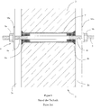
- a formwork 1, as in the FIG. 1 is known from the prior art.
- Two shuttering panels 2a, 2b are arranged opposite each other at a distance of the thickness of a concrete element 3 to be produced.
- the shuttering plates 2a, 2b are therefore used as Negative form for the concrete element 3.
- the formwork panels 2a, 2b are mostly made of wood or metal.
- a frame construction made of wood or metal profiles are attached to the side facing away from the concrete element 3 side of the shuttering plates 2a, 2b respectively (in FIG. 1 not shown).
- the formwork panels 2a, 2b are interconnected by a plurality of formwork anchors 4.
- a single shuttering anchor 4 has a threaded anchor rod 5, which penetrates the shutter plates 2a, 2b through two opposite passage openings 6a, 6b.
- a cladding tube 7 is disposed between the shutter plates 2a, 2b.
- the cladding tube 7 on both end faces abutment elements 8a, 8b, which transmits the pressure forces of the shuttering anchor 4 on the shutter plates 2a, 2b.
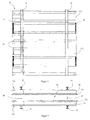
- the in the FIGS. 2 and 3 shown formwork 11 for producing a concrete element has two opposing formwork elements 13a, 13b. Between the formwork elements 13a, 13b, a casting space 15 is provided, which serves to receive flowable concrete, which cures to a concrete element to be produced.
- the formwork elements 13a, 13b have formwork panels 17a, 17b which face the casting space 15.
- the formwork panels 17a, 17b are adapted in their lengths and widths to the concrete element to be produced. Since formwork panels commercially available up to a height of 2 meters on the market, several formwork panels 17a, 17b can be stacked to produce concrete elements with a height of more than 2 meters.
- the formwork panels 17a, 17b are fastened to formwork supports 19 with nails or screws.
- the formwork beams 19 ensure sufficient stability Formwork elements 13a, 13b, when concrete is abandoned in the casting chamber 15. It is also conceivable, however, that can be dispensed with less load by the concrete element to be produced on the formwork support.
- each 2 profiles 21 are provided on the formwork elements 13 each 2 profiles 21.
- the profiles 21 are oriented orthogonal to the formwork beams 19 and are displaceable along the formwork beams.
- the profiles have a first end face 21a and a second end face 21b.
- 2 formwork beams 19a, 19b serve the profiles 21 as guide rails.
- the profiles 21 are designed to be displaceable, that an axis 23, which is arranged orthogonal to the longitudinal direction of the respective profile 21 on selbigem, between the formwork beams 19a, 19b protrudes.
- shuttering walls 17b without shuttering support 19 can be used.
- the shuttering walls 17a, 17b, the shuttering supports 19, if used, and the profiles 21 are preferably made of wood. However, it is conceivable that other materials such as plastic, steel or a combination of the listed materials are used.
- the profiles are 21 H-profiles, but other profile cross sections are possible.
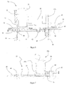
- a plurality of tension elements 29 are provided (FIG. FIGS. 5 to 9 ) having a first and a second ferrule part 31a, 31b.
- the clamp members 31a, 31b each have a rod 33 and 35, respectively, which serve clamping jaws 37 and 39 as guide rails.
- the jaws 37 and 39 along the rods 33 and 35 are adjustable, the jaws 37 and 39 cooperate with spindles 41 and 43 together.
- the Spindles 41 and 43 are rotatable on the rods 33 and 35 by extensions 42,44, in which bushings are provided with external thread, supported.
- FIG. 6 It will be appreciated that the hooks 45 and 47 disengage from the anchor bolt 49 as they are displaced relative to one another. This detail is significant when the constraining members 31a and 31b, respectively, are to be removed from the anchor bolt 49 after curing of the concrete element to be produced.
- the hook 47 is Z-shaped such that it overlaps the hook 45 when the hooks 45 and 47 engage around the anchor bolt 49.
- a U-shaped spacer 59 is disposed within the casting chamber 15, which may preferably be made in plastic or other suitable material.
- Front side have the spacers 59 in FIG. 8 illustrated webs 69a, 69b, which are spaced apart such that their distance corresponds to the width of the hooks 45,47.
- the ferrule 31a can not be used. In this case, multiple pairs of ferrules 31b are used to clamp the shuttering elements 13a, 13b.
- clamping elements 55 are provided at the end faces 21b of the profiles 21. These preferably consist of two threaded rods 61, which penetrate with their ends in each case two connecting profiles 63. The connection profiles 63 rest on the profile ends. The clamping elements 55 are tightened by nuts 65. As a resistance to the tensile force of the clamping elements 55 55 spacers 67 are provided between the profiles 21 at the level of the clamping elements. On further spacers within the casting chamber 15 can be dispensed with because of the stability of the shell element 13a, 13b.
- FIG. 9 the tensioning device consisting of the first and second ferrule part 31a, 31b is shown in a perspective view.
- FIG. 9 shows that the clamping jaws 37,39 can be flattened wedge-shaped at their upper free ends.
- the clamping jaws 37,39 can be easily detachably connected to the respective profile 21 by this shaping.
- a clip in the industry also referred to as quick release, which includes the wedge-shaped end and the clamping jaw facing flange of the profile to be hit on the wedge.
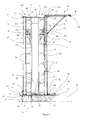
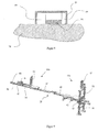
- the formwork 11 also comprises a fold-out device 70 for constructing a concreting platform, which in FIG. 4 is shown.
- a support 77 is added, which serves the profile 21 as a guide.
- a catwalk support 71 is pivotally connected to the support 77 with a first end 72a.
- a railing support 73 is articulated.
- a strut 75 is articulated at a short distance from the second end 72b of the catwalk support 71.
- the lever arm 99 is locked in its unfolded position in the hinge, by which it is connected to the holding plate 95 a.
- This can be achieved, for example, that the necessary for the function of the rotary joint through hole on the lever arm 99 is designed as a slot.
- the lever arm in its unfolded position by gravity is slightly downward in the direction of the support plate 93 movable.
- the lever arm is to be pulled upwards and is then pivotable relative to the retaining plate 95a.
- the device 70 is double secured against unwanted pivoting by the telescopic rod 101 and the lever arm 99. Due to the double Verschwenkrion the device 70 is also suitable to carry heavy loads, such as a concrete spill container.
- a holding element 103 is shown, which is able to hold the profile 21 on a formwork support 19.
- the holding element 103 has a first holding claw 105.
- the holding claw 105 is pushed onto the flange of the profile 21 and comprises it.
- a web 107 is arranged substantially orthogonal to selbiger.
- the web 107 has at its free end two recesses 109a, 109b which serve to receive a clamping wedge, preferably a double clamping wedge 111. Since the Doppelklemmkeil 111 consists of two interconnected clamping wedges, a high clamping force of the holding member 103 is achieved.
- a second retaining claw 113 which is L-shaped in its cross-section, is penetrated by the web 107.
- the profile 21 and the formwork support 19 are aligned substantially orthogonal to each other. That's why it matters in that the first and second retaining claws 105, 113 are likewise oriented orthogonally with respect to one another in order to be able to reliably cover the profile and the formwork support.
- the double clamping wedge 111 is knocked into the recesses 109a, 109b, the first and second retaining claws 105, 113 are pulled together. This causes the holding claws 105,113 in turn pull the profile 21 to the formwork support 19.
- the double wedge 111 is receivable from both sides of the recesses 109a, 109b in selbigen. Which side is selected depends primarily on the available space (clamping wedge 111 in FIG. 12 shown in dashed lines). The connection between the profile 21 and formwork support 19 is quickly solved by the Doppelklemmkeil 111 is beaten from the recesses.
- the invention also includes a holding device 115, which in the FIGS. 14 and 15 is shown.
- the holding device 115 serves for the rapid connection of two adjacent formwork elements 13 at their facing side edges.
- the holding device 115 comprises a first and second jaw 117,119 and a clamping wedge 121.
- the second jaw 119 preferably has a rectangular cross-section hollow profile in which the first jaw 117, preferably in the form of a rail, is slidably received.
- holding webs 121a, 121b are arranged. With these retaining webs, the two adjacent formwork elements 13 are included, for example, on a frame construction provided in the region of the side edges.
- the facilitated positioning of the holding device 115 on the frame structures are handles 116.
- the first and second clamping jaw 117,119 By relative displacement of the first and second clamping jaw 117,119 to each other, the holding webs surround the frame of the two formwork elements.
- the first jaw 117 has on one of its longitudinal sides a plurality of longitudinally arranged paragraphs in the form of rotary cylinders 123. According to the sum of the widths of the adjacent frame of the formwork elements one of the rotary cylinder serves as a paragraph for the clamping wedge 121.
- the holding device 115 is therefore flexible to the respective frame widths of the formwork elements adaptable.
- the coarse tuning of the spacing of the holding webs 121a, 121b relative to one another is effected by the rotary cylinder 123, which cooperates with the clamping wedge 121.
- the fine tuning by which the clamping effect of the holding webs 121a, 121b is constructed, is carried out by the clamping wedge 121.
- Through through holes 125a, 125b of the clamping wedge 121 penetrates the second Jaw 119 and is supported at the edges opposite the second jaw 119 from.
- the impact of the clamping wedge 121 causes the two clamping jaws to be pulled toward one another by the rotary cylinder 123, which is in contact with the clamping wedge. Just as quickly as the described clamping connection is constructed, this can be solved by knocking out of the clamping wedge 121 again. Since most of the shell elements available on the market for reasons of stability have a frame construction, the holding device 115 is also suitable to connect most of the formwork elements at their adjacent side edges.
- the shutter members 13a and 13b are manufactured.
- the formwork panels 17a and 17b which have commercially available dimensions, connected to the formwork beams 19 by nailing or screwing. If the concrete element to be produced has different dimensions than the formwork panels 17a, 17b, then the formwork panels 17a, 17b are cut to the appropriate mass.
- the profiles 21 are connected by means of rollers 25 with the profiles 21.
- the concrete element 28 adjoining the concrete element to be produced is provided with two spaced anchor bolts 49, which are offset into the still soft concrete or into previously drilled holes.
- the anchor bolts 49 are positioned in the concrete element 28 so that they are located approximately centrally between the shutter elements 13a, 13b after displacement of the shutter elements 13a, 13b.
- the first two parts 31a are hung with the hooks 45 in the anchor bolts 49.
- a front board 57 is arranged to better distribute the pressure of the spindle 53 on the concrete element 28 and to level unevenness on the concrete element 28.
- the rotation of the spindle 41 causes the first ferrule 31a to be pulled against the concrete element 28.
- the clamp parts 31a are aligned horizontally.
- the clamping elements 31b are also hung with the hooks 47 on the anchor bolt 49.
- the jaws are pre-adjusted so that after the displacement of the formwork elements 13a, 13b, a distance between the same results, which corresponds to the thickness of the concrete element to be produced.
- the profiles 21 are displaced so that the clamping jaws 37 act on it.
- the clamping jaws 37 are moved freely along the spindles 41 and guided by the rod 33 until the clamping jaws 37 act on the profiles 21.
- the threaded sleeves 48 serve for the final pressing of the clamping jaws 37 to the profiles 21, the threaded sleeves 48 serve.
- the hooks 45,47 are removable after curing of the concrete element to be produced, they are protected by spacers 59 in the form of a U-profile.
- the spacers 59 must be dimensioned such that the hooks 45, 47 can be released from the anchor bolts 49 without the hooks 45, 47 becoming jammed with the spacers 59.
- the webs 69a, 69b broken at the spacers and thereby give the entire cross section of the spacers 59 free.
- the breaking out is particularly simple, since the webs 69a, 69b are connected to the spacers 59 via predetermined breaking points.
- the spacers 59 also serve the spacing of the formwork elements 13a and 13b.
- the profiles 21 of the shell element 13b are likewise positioned so that the clamping jaws 39 can engage therewith.
- the catwalk carrier 71 is pivoted to a second position in which it is oriented perpendicular to the profile 21 and comes to bear with its first end 72a on the second end face of the profile 21.
- the strut 75 is then supported on an extension 79 on the profile 21.
- the railing support 73 is pivoted in a clockwise direction in a vertical position relative to the catwalk carrier 71.
- the device 70 for constructing a concreting platform according to the second embodiment is constructed ( FIG. 11 )
- the device is received in its first position in a recess of the profile 21, for example in one of the recesses of an H-profile.
- Two of the four bolts 96 form an axis of rotation about which the device 70 can be swung out of the recess of the profile 21.
- the holding plates 95a, 95b and the support plate 93 abut against the profile 21.
- the holding plates 95a, 95b are rotatably connected to the profile by the other two bolts 96.
- the telescopic rod 101, the lever arm 99 and the catwalk support are arranged in this first position substantially parallel to each other.
- the telescopic rod 101 is now extended until the catwalk support 71 is pivoted in a horizontal position.
- the lever arm 99 raises the catwalk carrier 71 via the spacer 67 and the nuts 65.
- the spacer 67 and the device 70 therefore do not hinder each other.
- the length of the telescopic rod for example by a split pin, can be fixed.
- the lever arm slot 99 By provided on the lever arm slot 99, the lever arm locked to the first holding plate 95 a, as already stated above.
- the lengths of the telescopic rod 101, the support plate 93, the lever arm 99 and the catwalk support 71 are preferably dimensioned such that these elements together according to a right-angled triangle FIG. 11 form.
- the devices 70 are space-saving and captive in the Profiles added. At the construction site, the devices 70 are ready within a very short time to hold a catwalk and railing. A concreting platform is therefore set up very quickly.
Landscapes
- Engineering & Computer Science (AREA)
- Architecture (AREA)
- Mechanical Engineering (AREA)
- Civil Engineering (AREA)
- Structural Engineering (AREA)
- Forms Removed On Construction Sites Or Auxiliary Members Thereof (AREA)
Applications Claiming Priority (1)
| Application Number | Priority Date | Filing Date | Title |
|---|---|---|---|
| CH01058/09A CH701411A1 (de) | 2009-07-08 | 2009-07-08 | Schalung und Verfahren zum Aufbau einer Schalung. |
Publications (2)
| Publication Number | Publication Date |
|---|---|
| EP2273038A2 true EP2273038A2 (fr) | 2011-01-12 |
| EP2273038A8 EP2273038A8 (fr) | 2011-04-06 |
Family
ID=42983313
Family Applications (1)
| Application Number | Title | Priority Date | Filing Date |
|---|---|---|---|
| EP10168957A Withdrawn EP2273038A2 (fr) | 2009-07-08 | 2010-07-08 | Coffrage et procédé de montage d'un coffrage |
Country Status (2)
| Country | Link |
|---|---|
| EP (1) | EP2273038A2 (fr) |
| CH (1) | CH701411A1 (fr) |
Cited By (4)
| Publication number | Priority date | Publication date | Assignee | Title |
|---|---|---|---|---|
| CN112193127A (zh) * | 2020-10-23 | 2021-01-08 | 兰州银利电器设备有限责任公司 | 一种移动接触网架设装置及架设方法 |
| CN116163513A (zh) * | 2023-03-23 | 2023-05-26 | 苏州拓恒建筑科技有限公司 | 一种钢框可调柱模板 |
| CN116201986A (zh) * | 2021-11-30 | 2023-06-02 | 中核第七研究设计院有限公司 | 全螺栓装配式专用设备支撑钢框架 |
| EP4382695A1 (fr) * | 2022-12-09 | 2024-06-12 | DOKA GmbH | Procédé de montage d'une unité de coffrage |
Families Citing this family (1)
| Publication number | Priority date | Publication date | Assignee | Title |
|---|---|---|---|---|
| CN102787716B (zh) * | 2012-08-22 | 2014-07-23 | 中建一局华江建设有限公司 | 欧式镂空板尖顶造型结构模板体系及施工方法 |
Family Cites Families (9)
| Publication number | Priority date | Publication date | Assignee | Title |
|---|---|---|---|---|
| US1291257A (en) * | 1918-07-01 | 1919-01-14 | Jacob Mullen Thompson | Concrete-wall-mold device. |
| GB227736A (en) * | 1924-07-21 | 1925-01-22 | Thomas Wood | Improvements in and connected with the erection of concrete buildings |
| US2740182A (en) * | 1952-12-22 | 1956-04-03 | Arthur J Harder | Interlocking devices for concrete wall form panels |
| GB2046341A (en) * | 1979-04-17 | 1980-11-12 | Martinenghi A | Method of and forms for moulding concrete partition walls |
| FR2615887B1 (fr) * | 1987-05-27 | 1993-05-28 | Chiappalone Luigi | Systeme de calage rapide pour trappons de coffrage des murs banches, utilisable pour differentes longueurs et epaisseurs de murs |
| FR2653807B3 (fr) * | 1989-10-31 | 1992-08-14 | Monetta Pierre | Serre-joints double pour coffrages a beton. |
| JP2005282080A (ja) * | 2004-03-29 | 2005-10-13 | Akemasa Kurotani | コンクリート型枠用間隔保持具 |
| EP1799936A1 (fr) * | 2004-09-24 | 2007-06-27 | Stanley Bryant | Procede et appareil de construction |
| US20070069104A1 (en) * | 2005-09-23 | 2007-03-29 | Kenneth Morin | Concrete forming structure frame locking device |
-
2009
- 2009-07-08 CH CH01058/09A patent/CH701411A1/de unknown
-
2010
- 2010-07-08 EP EP10168957A patent/EP2273038A2/fr not_active Withdrawn
Non-Patent Citations (1)
| Title |
|---|
| None |
Cited By (6)
| Publication number | Priority date | Publication date | Assignee | Title |
|---|---|---|---|---|
| CN112193127A (zh) * | 2020-10-23 | 2021-01-08 | 兰州银利电器设备有限责任公司 | 一种移动接触网架设装置及架设方法 |
| CN112193127B (zh) * | 2020-10-23 | 2023-11-10 | 兰州银利电器设备有限责任公司 | 一种移动接触网架设装置及架设方法 |
| CN116201986A (zh) * | 2021-11-30 | 2023-06-02 | 中核第七研究设计院有限公司 | 全螺栓装配式专用设备支撑钢框架 |
| EP4382695A1 (fr) * | 2022-12-09 | 2024-06-12 | DOKA GmbH | Procédé de montage d'une unité de coffrage |
| WO2024121282A1 (fr) * | 2022-12-09 | 2024-06-13 | Doka Gmbh | Procédé de construction d'une unité de coffrage |
| CN116163513A (zh) * | 2023-03-23 | 2023-05-26 | 苏州拓恒建筑科技有限公司 | 一种钢框可调柱模板 |
Also Published As
| Publication number | Publication date |
|---|---|
| CH701411A1 (de) | 2011-01-14 |
| EP2273038A8 (fr) | 2011-04-06 |
Similar Documents
| Publication | Publication Date | Title |
|---|---|---|
| DE3140287A1 (de) | "vorrichtung zur herstellung geschosshoher betonwaende" | |
| EP2273038A2 (fr) | Coffrage et procédé de montage d'un coffrage | |
| DE3140142A1 (de) | Systemschalung fuer betondecke mit unterzug | |
| EP0350525B1 (fr) | Procédé pour la réalisation de murs de constructions et système de coffrage | |
| DE2217584B2 (de) | Kletterschalung für eine Betonwandschalung | |
| DE1803626A1 (de) | Schalgeruest | |
| EP1126091A2 (fr) | Support de montage et procédé utilisant ce support pour monter un élément préfabriqué sur une partie de bâtiment | |
| DE19928757C2 (de) | Montageträgersystem und Verfahren zur Montage eines Fertigbauteils an einem Gebäudeteil | |
| DE1804002A1 (de) | Schalung fuer aus Beton zu giessende Deckentraeger | |
| DE102016111211B4 (de) | Schalungssystem für die Errichtung niedriger Bauabschnitte aus Ortbeton | |
| DE841722C (de) | Form zur Herstellung von Bauplatten | |
| WO1984000189A1 (fr) | Procede pour le betonnage de parois et coffrage pour sa mise en oeuvre | |
| AT412359B (de) | Schalung | |
| DE888161C (de) | Aus einzelnen vorher gefertigten Rahmen gebildetes Rohrbaugeruest | |
| DE3107844C2 (de) | Schalungselement für die Herstellung von Bauwerken aus Beton | |
| DE2436088A1 (de) | Verfahrbare schalungsvorrichtung | |
| DE10111344B4 (de) | Zwinge zum Verwenden bei verschiedenen Schalungen im Stahlbetonbau | |
| EP0480295B1 (fr) | Ensemble pour la construction d'une maison d'habitation ou de vacances | |
| DE3807764C2 (fr) | ||
| DE29705696U1 (de) | Vorrichtung zur Vereinfachung der Ein- und Ausschalung von Deckenflächen im Hoch- und Tiefbau | |
| EP0857834A1 (fr) | Méthode et échaffaudage pour ériger des murs en béton | |
| DE832203C (de) | Verfahren zur Erstellung von Massivbauten | |
| DE2415013A1 (de) | Haltevorrichtung fuer die schalung eines spundwandholmes | |
| DE815693C (de) | Lehrgeruest zum Mauern von Waenden | |
| DE102024109054A1 (de) | Trägerelement, Arbeitsplattform, Klettersystem, und Verfahren |
Legal Events
| Date | Code | Title | Description |
|---|---|---|---|
| PUAI | Public reference made under article 153(3) epc to a published international application that has entered the european phase |
Free format text: ORIGINAL CODE: 0009012 |
|
| AK | Designated contracting states |
Kind code of ref document: A2 Designated state(s): AL AT BE BG CH CY CZ DE DK EE ES FI FR GB GR HR HU IE IS IT LI LT LU LV MC MK MT NL NO PL PT RO SE SI SK SM TR |
|
| AX | Request for extension of the european patent |
Extension state: BA ME RS |
|
| STAA | Information on the status of an ep patent application or granted ep patent |
Free format text: STATUS: THE APPLICATION IS DEEMED TO BE WITHDRAWN |
|
| 18D | Application deemed to be withdrawn |
Effective date: 20130201 |