EP0050519A2 - Dispositif de combustion à lit fluidisé - Google Patents
Dispositif de combustion à lit fluidisé Download PDFInfo
- Publication number
- EP0050519A2 EP0050519A2 EP81304919A EP81304919A EP0050519A2 EP 0050519 A2 EP0050519 A2 EP 0050519A2 EP 81304919 A EP81304919 A EP 81304919A EP 81304919 A EP81304919 A EP 81304919A EP 0050519 A2 EP0050519 A2 EP 0050519A2
- Authority
- EP
- European Patent Office
- Prior art keywords
- slots
- air
- combustion apparatus
- tubes
- combustion chamber
- Prior art date
- Legal status (The legal status is an assumption and is not a legal conclusion. Google has not performed a legal analysis and makes no representation as to the accuracy of the status listed.)
- Granted
Links
- 238000002485 combustion reaction Methods 0.000 claims abstract description 50
- 238000001816 cooling Methods 0.000 claims abstract description 5
- 239000002245 particle Substances 0.000 claims abstract description 5
- 239000002826 coolant Substances 0.000 claims description 8
- 230000001105 regulatory effect Effects 0.000 claims description 6
- 238000009826 distribution Methods 0.000 claims description 4
- 239000012530 fluid Substances 0.000 claims description 2
- 239000000446 fuel Substances 0.000 description 30
- XLYOFNOQVPJJNP-UHFFFAOYSA-N water Substances O XLYOFNOQVPJJNP-UHFFFAOYSA-N 0.000 description 14
- 239000007788 liquid Substances 0.000 description 8
- 239000004449 solid propellant Substances 0.000 description 7
- 239000003245 coal Substances 0.000 description 5
- 239000000463 material Substances 0.000 description 5
- VYPSYNLAJGMNEJ-UHFFFAOYSA-N Silicium dioxide Chemical compound O=[Si]=O VYPSYNLAJGMNEJ-UHFFFAOYSA-N 0.000 description 3
- 239000007787 solid Substances 0.000 description 3
- LFQSCWFLJHTTHZ-UHFFFAOYSA-N Ethanol Chemical compound CCO LFQSCWFLJHTTHZ-UHFFFAOYSA-N 0.000 description 2
- PPBRXRYQALVLMV-UHFFFAOYSA-N Styrene Chemical compound C=CC1=CC=CC=C1 PPBRXRYQALVLMV-UHFFFAOYSA-N 0.000 description 2
- 238000010276 construction Methods 0.000 description 2
- 230000003247 decreasing effect Effects 0.000 description 2
- 239000002184 metal Substances 0.000 description 2
- 238000012544 monitoring process Methods 0.000 description 2
- 238000005192 partition Methods 0.000 description 2
- 239000000779 smoke Substances 0.000 description 2
- 239000004575 stone Substances 0.000 description 2
- 239000000126 substance Substances 0.000 description 2
- 239000004215 Carbon black (E152) Substances 0.000 description 1
- 235000019738 Limestone Nutrition 0.000 description 1
- NINIDFKCEFEMDL-UHFFFAOYSA-N Sulfur Chemical compound [S] NINIDFKCEFEMDL-UHFFFAOYSA-N 0.000 description 1
- 239000005864 Sulphur Substances 0.000 description 1
- 238000009825 accumulation Methods 0.000 description 1
- 230000000712 assembly Effects 0.000 description 1
- 238000000429 assembly Methods 0.000 description 1
- 230000015572 biosynthetic process Effects 0.000 description 1
- 230000001276 controlling effect Effects 0.000 description 1
- 230000001419 dependent effect Effects 0.000 description 1
- 230000000694 effects Effects 0.000 description 1
- 238000010892 electric spark Methods 0.000 description 1
- 238000005516 engineering process Methods 0.000 description 1
- 239000010419 fine particle Substances 0.000 description 1
- 239000003502 gasoline Substances 0.000 description 1
- 239000011521 glass Substances 0.000 description 1
- 239000013529 heat transfer fluid Substances 0.000 description 1
- 229930195733 hydrocarbon Natural products 0.000 description 1
- 150000002430 hydrocarbons Chemical class 0.000 description 1
- 229910052500 inorganic mineral Inorganic materials 0.000 description 1
- 239000003350 kerosene Substances 0.000 description 1
- 239000006028 limestone Substances 0.000 description 1
- 238000004519 manufacturing process Methods 0.000 description 1
- 238000005555 metalworking Methods 0.000 description 1
- 238000000034 method Methods 0.000 description 1
- 239000011707 mineral Substances 0.000 description 1
- 238000013021 overheating Methods 0.000 description 1
- 230000000630 rising effect Effects 0.000 description 1
- 239000004576 sand Substances 0.000 description 1
- 239000000377 silicon dioxide Substances 0.000 description 1
- 238000005245 sintering Methods 0.000 description 1
- 239000007921 spray Substances 0.000 description 1
- 238000011144 upstream manufacturing Methods 0.000 description 1
Images


Classifications
-
- B—PERFORMING OPERATIONS; TRANSPORTING
- B01—PHYSICAL OR CHEMICAL PROCESSES OR APPARATUS IN GENERAL
- B01J—CHEMICAL OR PHYSICAL PROCESSES, e.g. CATALYSIS OR COLLOID CHEMISTRY; THEIR RELEVANT APPARATUS
- B01J8/00—Chemical or physical processes in general, conducted in the presence of fluids and solid particles; Apparatus for such processes
- B01J8/18—Chemical or physical processes in general, conducted in the presence of fluids and solid particles; Apparatus for such processes with fluidised particles
- B01J8/1818—Feeding of the fluidising gas
-
- F—MECHANICAL ENGINEERING; LIGHTING; HEATING; WEAPONS; BLASTING
- F23—COMBUSTION APPARATUS; COMBUSTION PROCESSES
- F23C—METHODS OR APPARATUS FOR COMBUSTION USING FLUID FUEL OR SOLID FUEL SUSPENDED IN A CARRIER GAS OR AIR
- F23C10/00—Fluidised bed combustion apparatus
-
- F—MECHANICAL ENGINEERING; LIGHTING; HEATING; WEAPONS; BLASTING
- F23—COMBUSTION APPARATUS; COMBUSTION PROCESSES
- F23C—METHODS OR APPARATUS FOR COMBUSTION USING FLUID FUEL OR SOLID FUEL SUSPENDED IN A CARRIER GAS OR AIR
- F23C10/00—Fluidised bed combustion apparatus
- F23C10/18—Details; Accessories
- F23C10/20—Inlets for fluidisation air, e.g. grids; Bottoms
-
- F—MECHANICAL ENGINEERING; LIGHTING; HEATING; WEAPONS; BLASTING
- F23—COMBUSTION APPARATUS; COMBUSTION PROCESSES
- F23C—METHODS OR APPARATUS FOR COMBUSTION USING FLUID FUEL OR SOLID FUEL SUSPENDED IN A CARRIER GAS OR AIR
- F23C10/00—Fluidised bed combustion apparatus
- F23C10/18—Details; Accessories
- F23C10/24—Devices for removal of material from the bed
-
- F—MECHANICAL ENGINEERING; LIGHTING; HEATING; WEAPONS; BLASTING
- F23—COMBUSTION APPARATUS; COMBUSTION PROCESSES
- F23C—METHODS OR APPARATUS FOR COMBUSTION USING FLUID FUEL OR SOLID FUEL SUSPENDED IN A CARRIER GAS OR AIR
- F23C10/00—Fluidised bed combustion apparatus
- F23C10/18—Details; Accessories
- F23C10/28—Control devices specially adapted for fluidised bed, combustion apparatus
Definitions
- This invention relates to fluidized bed combustion, and more particularly to a fluidized bed combustion apparatus constructed to combust poor quality solid particulate fuel on a generally continuous basis, with concomitant removal of hot noncombustible substances.
- a fluidized bed combustion apparatus comprises: a combustion chamber; a distributor plate assembly at the bottom of the combustion chamber, slots in the distributor plate assembly to form air flow openings to the combustion chamber; air flow riser tubes projecting up through the plate assembly to a position elevated thereabove and having air inlets at the bottom and outlets at the top, and means for supplying air to the slots and to the risers.
- a fluidized bed combustion apparatus comprises: a fluid bed combustion chamber having a bottom distribution plate with sloped bottom walls terminating in ash outlet drop tubes projecting downwardly; cooling fins on said drop tubes exposed to ambient atmosphere; an auger conveyor beneath said drop tubes, having a housing with inlets thereinto communicant with said drop tubes to receive hot debris therefrom, and an outlet; said housing having a coolant flow chamber there-around; an auger in said housing for advancing hot debris from said inlets to said outlet, and coolant flow passages in said auger, whereby hot debris can be discharged from said combustion chamber through said drop tubes, into said auger conveyor for transfer to said outlet.
- the invention thus provides a fluidized bed combustor which is particularly suited for combustion of a variety of fuels, including poor quality coal, e.g. having over fifty percent stone and ash content.
- the combustor is capable of continuous or intermittent feed and concomitant classification of and discharge of hot debris.
- the classification function can be regulated via combustion air flow control through shield covered slots in sloped bottom surfaces of the distributor plate. Yet the rate of combustion is not dependent on the amount of air flow through the classification slots in that flow is also caused to occur through risers projecting above the sloped surfaces into the bed.
- the relative amounts of air flow through the slots and the risers is regulated by regulating the share of air flow to a first plenum for the slots and a second plenum for the risers.
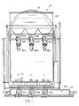
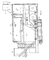
- the boiler 10 (Fig. 1 and 2) includes a pressure vessel 12 of conventional type. Associated therewith is a typical smoke box 14 leading to an exhaust stack 16.
- the pressure vessel is to contain water or other heat transfer fluid which may be converted to steam or vapour. It is to include conventional controls such as a water gauge glass 18, a feed water supply valve 17 with feed water controls, low water cut-off, and high and low water alarms 20. It has a surface blow off device 22 and a main stream outlet 24.
- the boiler includes a heat exchanger (not shown) which may be of the construction shown in U.S. Patent No. 4 228 767 and to which heat for generation of steam is supplied from a fluidized bed combustor assembly 26 in the lower portion of the apparatus.
- the combustor is composed of three adjacent fluidized bed zones 28a, 28b and 28c, each capable of independent operation.
- each bed would include a fluidizable bed material such as silica sand or the like.
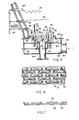
- This multiple of fluidized beds is located at the bottom of a combustion chamber 30 ( Figure 3), defined by chamber walls 32 which typically would be refractory lined (as depicted in Figure 3) or water filled (as depicted in Figure 5). The lower portion of the walls converge downwardly as depicted.
- Each distributor plate assembly 33 ( Figure 5) includes a housing 34 which defines a first upper plenum 36 and a second lower plenum 38 separated by a partition 40. Projecting down into the upper plenum 36 is an inverted frustopyramidally-shaped distributor plate surface area 42 terminating at its lower end in a central opening 44 communicating with a vertical drop tube, e.g. 46c, depending therefrom for controlled removal of hot debris from the fluidized bed during operation as described hereinafter.
- a vertical drop tube e.g. 46c
- This surface area 42 is formed with pierced or punched elongated slots 49 and integral vertically offset elongated shields 51 thereover, the shields being formed by the metal offset from the plate surface curing formation of the slots.
- the long dimension of the individual slots is orientated toward the central opening 44 in the bottom of the distributor plate, i.e. down the sloping surfaces thereof.
- the slots and shields form laterally orientated air outlets.
- the technique for displacing metal plates in this fashion is conventional in the metal working industry.
- the combustion air flow through these outlets supplies a portion of the combustion air for the respective fluizided bed, also serving as a portion of the fluidizing air for the bed, and further causing particulate classification along the sloped surface of this surface area.
- the slots and outlets communicate with the upper first plenum 36 so that air flow through the plenum emerges into the combustion chamber through these outlets.
- a plurality of riser tubes Projecting upwardly from the lower second plenum 38 (Fig. 5) to an elevated position above the surface 42 is a plurality of riser tubes, usually cylindrical, formed of a first set of riser tubes 50 and a second set 52. Both sets of riser tubes project substantially above the surface area 42, with risers 52 projecting above risers 50. Risers 52 have air outlet openings adjacent the top thereof located above the air outlet openings adjacent the top of risers 50. Both sets of risers have inlet openings at the bottoms communicant with the lower plenum 38 for flow of the other portion of combustion and fluidizing air therethrough into the combustion chamber.
- risers 52 Also adjacent the bottom of risers 52 is a plurality of respective liquid fuel nozzles 56 supplied by a liquid fuel inlet conduit 58 for introduction of a light liquid fuel such as alcohol, gasoline, kerosene, styrene, and/or other light liquid hydrocarbon fuels.
- the nozzles are orientated to spray the fuel into the interior walls of the riser trubes 52 for conductance of the fuel by the rising film principle up through the tubes along with the air flowing upwardly therethrough, and discharge of both into the bed through the same outlets.
- Air is propelled into the lower plenum 38 of the housing 34 under force through an inlet 60 (Fig. 5).
- Means is provided for controlling the amount of the air which flows to the riser tubes and the amount which flows to the slots in surface 42. In the particular embodiment depicted, this is done by a pivotably movable baffle or damper 62 positioned in the partition 40 between the plenum 38 and the plenum 36, thereby to regulate the proportion of the air which flows to the first plenum and thus out of the slots 49 as opposed to the portion which flows from the plenum 38 to the riser tubes 50 and 52.
- This proportioning control means could alternatively be positioned upstream of both plenums such that the air to the plenum 36 passes directly thereto rather than through the plenum 38, or the air could be made to flow first to the plenum 36, with part of it being controllably discharged to the plenum 38.
- Each bed has its own such baffle or damper control.
- Each also has its own air supply means such as a draft fan 64 (Fig. 4). If desired, additional air outlet ports 45 can be provided within the drop tube 44 to assist.in the classification function to be described hereinafter.
- Temperature measuring elements such as thermocouples 70 projecting up to different levels within the bed are employed to monitor the bed temperature at these levels. These thermocouples are supported by tubes 72 (Fig. 5) adjacent the riser tubes for the air and fuel, and connect to temperature monitoring indicators. These sensors can for example detect overheating which may result in sintering or glassing of the bed material. Such can activate an alarm, and/or effect safety shutdown.
- Each of the drop tubes 46a, 46b, and 46c (Fig. 1) for the hot debris includes cooling fins 47 (Fig. 5) therearound, in contact with the air flowing through the lower plenum 38. This not only maintains the drop tubes within a controlled temperature range but also preheats the combustion air for thermal efficiency.
- the lower end of each drop tube has a flange for connection to an inlet on the debris conveyor apparatus therebelow, and described hereinafter.
- an electric spark igniter 71 with controls 73 (Fig. 3), and a light liquid fuel supply 73a and return 73b.
- level sensors 76, 78 and 80 are interconnected with transmitters 82 to indicate bed level. If desired, the sensors can be connected.to automation bed level controls.
- the decreased bed level of the active bed can cause the inactive bed to be fluidized for a limited time, without fuel combustion therein, to redistribute the particulate bed material back to the active bed.
- the sensing of a low or high bed can sound an alarm, start or stop under-bed debris removal equipment, start or stop fuel in-feed to the bed, and/or start or stop the forced draft fan for the bed.
- the main fuel for the fluidized bed combustor is typically a solid particulate fuel such as coal.
- This solid fuel is preferably supplied from a fuel hopper 90, optionally including a limestone hopper 91 associated therewith for control of sulphur emissions in known fashion.
- the individual fluidized beds are respectively supplied with fuel from this hopper by individual feed augers in housings 92a, 92b and 92c (Fig. 1) driven by appropriate motors 94a, 94b and 94c, to advance the feed down appropriate chutes 96a, 96b or 96c, dropping the fuel into each bed.
- the individual augers powered by motors 94a, 94b and 94c are metering screws, with motors 94a, 94b and 94c being of variable speed type. These cooperate with individual constant speed motor- driven screws, e.g. 98c (Fig. 4), which push the feed into the individual beds.
- the fuel feed can be variable speed, intermittent or continuous as necessary.
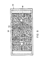
- the hot debris discharged from the fluidized beds through the drop tubes enters a water cooled conveyor system 100 (Fig. 1, Fig. 9). More specifically, a plurality of conveyors 102a, 102b.and 102c have upper openings communicating with the lower ends of the drop tubes to receive the hot noncombustible debris therefrom.
- These conveyors include housings 104a, 104b and 104c (Fig. 9) with coolant flow passages, usually for water, and an auger with coolant flow passages, usually for water. More specifically, (Fig.
- a cold water source 105 supplies coolant to a line 107 leading to individual auger passages 110a,-110b and 110c, which then flows back from the augers to the housings 104a, 104b, and 104c through lines 106a, 106b, and 106c.
- the coolant discharges through lines 108a, 108b, and 108c to an outlet 122.
- the hot debris is preferably advanced by these conveyors to a cross conveyor 112 (Fig. 9) which also has a water cooled auger using an inlet line 114 from the source 105, the output from the auger flowing through a line 116 to a water cooled housing 118 to be discharged therefrom through a line 120 to the outlet 122, to be fed to the boiler, if desired, for thermal efficiency.
- the individual beds are selectively fluidized by forcefully propelling air from the draft fans, e.g. 64, into the selected distributor plate assemblies and more specifically into the lower plenums 38 thereof.
- the individual dampers 62 are regulated to achieve desired air flow proportioning.
- One portion of the air is propelled into the combustion chamber through the slots 49 and the other portion through the lateral outlets in the tops of the riser tubes 50 and 52, to fluidize the particulate bed.
- the supply of light liquid fuel is decreased or terminated, causing continued operation to be solely by combustion of the solid fuel.
- the system can be automatically shut down in response to excess temperatures detected by the temperature sensors 70.
- the solid fuel infeed is preferably controlled in response to pressure controls of the boiler, i.e. adding more fuel if more heat is required.
- Combustion of the solid fuel causes creation of ash and concentration of small stones and/or other noncombustible substances, i.e. debris present in the fuel. This is continuously removable on a controlled basis during operation. For example, the unit has been demonstrated to successfully operate on poor quality coal having more than fifty percent mineral and ash content, yet without the typically expected necessity of shutdown every few hours to clean out the large quantity of debris.
- the unit automatically eliminates the debris on a continued basis. This is done by the special structure and arrangement of the distribution plate assembly.
- the controlled portion of air through the outlets 49 of the plate causes dynamic, continuous classification of the particulates along the sloped surface area 42, and can be adjusted for the fuel encountered without altering the total combustion air input since the remainder is injected through the riser tubes projecting above the surface 42.
- the air flow at this inverted frustopyramidal surface causes controlled classification of the particles based upon size, the larger hot particles slowly migrating down the slope to the drop tube, and dropping down the cooled tube to the water cooled conveyor system.
- the conveyors 102a, 102b and 102c advance the debris while cooling it further, to the cross conveyor 112 which cools and propels it to the discharge outlet 113.
- the finer particles of uncombusted or partially combusted materials migrate upwardly into the fluidized bed for complete combustion.
- Very fine particles of ash or fuel which may be carried with the exhaust are separated out of the exhaust by a conventional separator or precepitator in the housing 15 below the smoke box, and recycled back through the return line 31 (Fig. 2) to the fluidized bed.
Landscapes
- Engineering & Computer Science (AREA)
- Chemical & Material Sciences (AREA)
- Combustion & Propulsion (AREA)
- Mechanical Engineering (AREA)
- General Engineering & Computer Science (AREA)
- Organic Chemistry (AREA)
- Chemical Kinetics & Catalysis (AREA)
- Fluidized-Bed Combustion And Resonant Combustion (AREA)
- Production Of Liquid Hydrocarbon Mixture For Refining Petroleum (AREA)
- Crucibles And Fluidized-Bed Furnaces (AREA)
Priority Applications (1)
| Application Number | Priority Date | Filing Date | Title |
|---|---|---|---|
| AT81304919T ATE24598T1 (de) | 1980-10-20 | 1981-10-20 | Wirbelbettverbrennungsvorrichtung. |
Applications Claiming Priority (2)
| Application Number | Priority Date | Filing Date | Title |
|---|---|---|---|
| US06/198,919 US4400150A (en) | 1980-10-20 | 1980-10-20 | Fluidized bed combustor distributor plate assembly |
| US198919 | 1994-02-18 |
Publications (3)
| Publication Number | Publication Date |
|---|---|
| EP0050519A2 true EP0050519A2 (fr) | 1982-04-28 |
| EP0050519A3 EP0050519A3 (en) | 1982-09-08 |
| EP0050519B1 EP0050519B1 (fr) | 1986-12-30 |
Family
ID=22735443
Family Applications (1)
| Application Number | Title | Priority Date | Filing Date |
|---|---|---|---|
| EP81304919A Expired EP0050519B1 (fr) | 1980-10-20 | 1981-10-20 | Dispositif de combustion à lit fluidisé |
Country Status (8)
| Country | Link |
|---|---|
| US (1) | US4400150A (fr) |
| EP (1) | EP0050519B1 (fr) |
| JP (1) | JPS57104009A (fr) |
| AT (1) | ATE24598T1 (fr) |
| AU (1) | AU544910B2 (fr) |
| BR (1) | BR8106723A (fr) |
| DE (1) | DE3175766D1 (fr) |
| ZA (1) | ZA816934B (fr) |
Cited By (3)
| Publication number | Priority date | Publication date | Assignee | Title |
|---|---|---|---|---|
| FR2519877A1 (fr) * | 1982-01-20 | 1983-07-22 | Charbonnages De France | Grille de fluidisation ainsi que foyer de combustion a grille inferieure de soufflage d'air et procede de traitement de matiere particulaire dans une chambre de fluidisation et/ou d'entrainement |
| EP0088638A3 (en) * | 1982-03-10 | 1983-11-09 | Montedison S.P.A. | Distributor for a fluidized bed reactor |
| GB2189164A (en) * | 1986-03-14 | 1987-10-21 | Univ Birmingham | Apparatus for fluidised beds |
Families Citing this family (17)
| Publication number | Priority date | Publication date | Assignee | Title |
|---|---|---|---|---|
| ZA811239B (en) * | 1980-03-04 | 1982-03-31 | Stone Platt Fluidfire Ltd | Boiler and method of heating liquid |
| US4419330A (en) * | 1981-01-27 | 1983-12-06 | Ebara Corporation | Thermal reactor of fluidizing bed type |
| JPS6298106A (ja) * | 1985-10-23 | 1987-05-07 | Babcock Hitachi Kk | 流動層装置およびその流動化方法 |
| US4623309A (en) * | 1985-11-20 | 1986-11-18 | Combustion Engineering, Inc. | Fluid bed combustor and apparatus for cooling particulate solids |
| US4693682A (en) * | 1986-05-12 | 1987-09-15 | Institute Of Gas Technology | Treatment of solids in fluidized bed burner |
| US5143486A (en) * | 1991-03-01 | 1992-09-01 | Riley Stoker Corporation | Flow promoter for fluidized solids |
| EP1753999B1 (fr) * | 2004-05-28 | 2013-11-20 | Alstom Technology Ltd | Dispositif a lit fluidise a agent comburant enrichi en oxygene |
| FR2870925B1 (fr) * | 2004-05-28 | 2006-12-29 | Alstom Technology Ltd | Dispositif a lit fluidise a agent comburant enrichi en oxygene |
| JP4828990B2 (ja) * | 2006-04-05 | 2011-11-30 | 共同カイテック株式会社 | バスダクト接続部の施工方法 |
| US9970683B2 (en) | 2008-03-11 | 2018-05-15 | Linde Engineering North America Inc. | Apparatus and method for flameless thermal oxidation at optimized equivalence ratios |
| FI120661B (fi) * | 2008-06-11 | 2010-01-15 | Yit Teollisuus Ja Verkkopalvel | Leijupetikattilan petimateriaalin ohjaussuppilo, leijupetikattila, menetelmä leijupetikattilassa, sisäsuppilo ja sen käyttö |
| FI20086192A7 (fi) * | 2008-12-12 | 2010-06-13 | Foster Wheeler Energia Oy | Kiertoleijureaktori happipolttoon, menetelmä sellaisen reaktorin käyttämiseksi ja menetelmä kiertoleijureaktorin muuttamiseksi |
| CN101900327B (zh) * | 2010-09-08 | 2011-06-22 | 山东希尔生物质能源有限公司 | 生物质燃料内循环机械流化床角管式锅炉 |
| US9759483B1 (en) * | 2011-08-24 | 2017-09-12 | Arizona Board Of Regents Acting For And On Behalf Of Northern Arizona University | Biomass drying system |
| CN103574597B (zh) * | 2013-11-21 | 2016-02-03 | 上海锅炉厂有限公司 | 一种循环流化床锅炉水冷落渣布风装置 |
| SE541321C2 (en) * | 2015-03-25 | 2019-07-02 | Vattenfall Ab | Bubbling fluidized bed combustion device and method for monitoring the fluidized bed in such a combustion device |
| CN114526477B (zh) * | 2022-02-17 | 2025-06-24 | 华北电力科学研究院有限责任公司 | 循环流化床机组冷渣器和低温省煤器优化方法、装置 |
Family Cites Families (17)
| Publication number | Priority date | Publication date | Assignee | Title |
|---|---|---|---|---|
| US3198499A (en) * | 1961-08-11 | 1965-08-03 | Kaiser Aluminium Chem Corp | Method and apparatus for supporting and heat treating |
| US3397657A (en) * | 1965-11-01 | 1968-08-20 | Tada Mitsuru | Apparatus for continuously burning wastes |
| US3799747A (en) * | 1968-04-27 | 1974-03-26 | Metallgesellschaft Ag | Fuel burner system for a fluidized bed |
| DK134450B (da) * | 1970-06-13 | 1976-11-08 | Morinaga Milk Industry Co Ltd | Forstøvningstørringsapparat til mælk og lignende mejeriprodukter. |
| GB1368352A (en) * | 1972-01-26 | 1974-09-25 | British Petroleum Co | Fluidised bed distributor plate |
| US3776150A (en) * | 1972-03-06 | 1973-12-04 | Awt Systems Inc | Fluidized bed system for solid wastes |
| US3861862A (en) * | 1972-09-05 | 1975-01-21 | Andrew B Steever | Fuel gun for fluidized bed reactor |
| GB1459766A (en) * | 1973-03-20 | 1976-12-31 | British Petroleum Co | Combustor |
| SE393825B (sv) * | 1974-05-29 | 1977-05-23 | Svenska Flaektfabriken Ab | Anordning for att vid transport av ett ban- eller arkformigt av luft uppburet material, framfora materialet i ett fixerat stabilt svevlege genom en eller flera passager av en behandlingsanleggning, foretredesvis ... |
| US4060041A (en) * | 1975-06-30 | 1977-11-29 | Energy Products Of Idaho | Low pollution incineration of solid waste |
| GB1591301A (en) * | 1976-08-26 | 1981-06-17 | British Petroleum Co | Fluidised bed |
| GB1604221A (en) * | 1977-05-02 | 1981-12-02 | Appa Thermal Exchanges Ltd | Removal of ash from fluidised beds |
| DE2814239C2 (de) | 1978-04-03 | 1985-11-14 | Steag Ag, 4300 Essen | Wirbelbettfeuerung für die Verbrennung von stückigem Brennstoff |
| US4177742A (en) * | 1978-04-05 | 1979-12-11 | Babcock-Hitachi Kabushiki Kaisha | Incinerator for burning waste and a method of utilizing same |
| US4284401A (en) * | 1978-08-03 | 1981-08-18 | Kawasaki Jukogyo Kabushiki Kaisha | Method and means for feeding fuel into fluidized-bed combustion apparatus |
| US4228767A (en) * | 1979-01-22 | 1980-10-21 | Johnston Boiler Company | Self contained boiler package utilizing atmospheric fluidized bed combustion |
| US4253824A (en) * | 1979-07-13 | 1981-03-03 | Energy Products Of Idaho | Tramp removal and bed recirculation system |
-
1980
- 1980-10-20 US US06/198,919 patent/US4400150A/en not_active Expired - Lifetime
-
1981
- 1981-10-07 ZA ZA816934A patent/ZA816934B/xx unknown
- 1981-10-08 AU AU76160/81A patent/AU544910B2/en not_active Ceased
- 1981-10-19 BR BR8106723A patent/BR8106723A/pt unknown
- 1981-10-20 EP EP81304919A patent/EP0050519B1/fr not_active Expired
- 1981-10-20 JP JP56166526A patent/JPS57104009A/ja active Pending
- 1981-10-20 AT AT81304919T patent/ATE24598T1/de active
- 1981-10-20 DE DE8181304919T patent/DE3175766D1/de not_active Expired
Cited By (4)
| Publication number | Priority date | Publication date | Assignee | Title |
|---|---|---|---|---|
| FR2519877A1 (fr) * | 1982-01-20 | 1983-07-22 | Charbonnages De France | Grille de fluidisation ainsi que foyer de combustion a grille inferieure de soufflage d'air et procede de traitement de matiere particulaire dans une chambre de fluidisation et/ou d'entrainement |
| US4628831A (en) * | 1982-01-20 | 1986-12-16 | Charbonnages De France | Hearth and process for fluidized-bed treatment of a fuel |
| EP0088638A3 (en) * | 1982-03-10 | 1983-11-09 | Montedison S.P.A. | Distributor for a fluidized bed reactor |
| GB2189164A (en) * | 1986-03-14 | 1987-10-21 | Univ Birmingham | Apparatus for fluidised beds |
Also Published As
| Publication number | Publication date |
|---|---|
| ZA816934B (en) | 1982-09-29 |
| AU544910B2 (en) | 1985-06-20 |
| AU7616081A (en) | 1982-04-29 |
| BR8106723A (pt) | 1982-07-06 |
| US4400150A (en) | 1983-08-23 |
| EP0050519B1 (fr) | 1986-12-30 |
| DE3175766D1 (en) | 1987-02-05 |
| JPS57104009A (en) | 1982-06-28 |
| EP0050519A3 (en) | 1982-09-08 |
| ATE24598T1 (de) | 1987-01-15 |
Similar Documents
| Publication | Publication Date | Title |
|---|---|---|
| US4400150A (en) | Fluidized bed combustor distributor plate assembly | |
| US4330502A (en) | Fluidized bed reactor | |
| EP0006307B1 (fr) | Chaudière | |
| US3769922A (en) | Fluid bed reactor pre-heating method and apparatus | |
| US4528917A (en) | Solid fuel burner | |
| EP0740109B1 (fr) | Dispositif de combustion à lit fluidisé | |
| EP0050518B1 (fr) | Dispositif de combustion à lit fluidisé | |
| JPS59112113A (ja) | 廃棄物焼却装置 | |
| JPS59500383A (ja) | 高速流動層ボイラ | |
| EP0028021A1 (fr) | Procédé et appareil de pyrolyse | |
| JP3990463B2 (ja) | 水冷燃焼火格子 | |
| US4499857A (en) | Fluidized bed fuel burning | |
| KR900000948B1 (ko) | 가연성 물질의 소각장치 | |
| NO154319B (no) | Forbrenningsapparat med fluidisert skikt. . | |
| US4628838A (en) | Fluidized bed combustion method | |
| FI94170C (fi) | Sisäisellä kierrolla varustettu leijukerroskattila ja menetelmä tämän ohjaamiseksi | |
| US4629421A (en) | Gas and solid particulate material heat exchanger | |
| US5588378A (en) | Combustion enhancement system with in-bed foils | |
| EP0028458A2 (fr) | Chaudières à vapeur à lit fluidisé | |
| US4228767A (en) | Self contained boiler package utilizing atmospheric fluidized bed combustion | |
| EP0044316A4 (fr) | Chambres de combustion a lit gicle et fluidise. | |
| JPH01203801A (ja) | 垂直伝熱管を有した流動床ボイラおよび該ボイラを用いた流動床温水ボイラ | |
| JPH0461243B2 (fr) | ||
| JPH0756361B2 (ja) | 流動層熱回収装置およびその制御方法 | |
| SU1638446A1 (ru) | Устройство дл сжигани недробленного твердого топлива |
Legal Events
| Date | Code | Title | Description |
|---|---|---|---|
| PUAI | Public reference made under article 153(3) epc to a published international application that has entered the european phase |
Free format text: ORIGINAL CODE: 0009012 |
|
| AK | Designated contracting states |
Designated state(s): AT BE CH DE FR GB IT LU NL SE |
|
| PUAL | Search report despatched |
Free format text: ORIGINAL CODE: 0009013 |
|
| AK | Designated contracting states |
Designated state(s): AT BE CH DE FR GB IT LU NL SE |
|
| 17P | Request for examination filed |
Effective date: 19830217 |
|
| GRAA | (expected) grant |
Free format text: ORIGINAL CODE: 0009210 |
|
| ITF | It: translation for a ep patent filed | ||
| RAP1 | Party data changed (applicant data changed or rights of an application transferred) |
Owner name: THE BRITISH PETROLEUM COMPANY P.L.C. |
|
| AK | Designated contracting states |
Kind code of ref document: B1 Designated state(s): AT BE CH DE FR GB IT LI LU NL SE |
|
| PG25 | Lapsed in a contracting state [announced via postgrant information from national office to epo] |
Ref country code: AT Effective date: 19861230 |
|
| REF | Corresponds to: |
Ref document number: 24598 Country of ref document: AT Date of ref document: 19870115 Kind code of ref document: T |
|
| REF | Corresponds to: |
Ref document number: 3175766 Country of ref document: DE Date of ref document: 19870205 |
|
| ET | Fr: translation filed | ||
| PLBE | No opposition filed within time limit |
Free format text: ORIGINAL CODE: 0009261 |
|
| STAA | Information on the status of an ep patent application or granted ep patent |
Free format text: STATUS: NO OPPOSITION FILED WITHIN TIME LIMIT |
|
| 26N | No opposition filed | ||
| ITTA | It: last paid annual fee | ||
| PGFP | Annual fee paid to national office [announced via postgrant information from national office to epo] |
Ref country code: DE Payment date: 19920826 Year of fee payment: 12 |
|
| PGFP | Annual fee paid to national office [announced via postgrant information from national office to epo] |
Ref country code: FR Payment date: 19920910 Year of fee payment: 12 |
|
| PGFP | Annual fee paid to national office [announced via postgrant information from national office to epo] |
Ref country code: SE Payment date: 19920914 Year of fee payment: 12 |
|
| PGFP | Annual fee paid to national office [announced via postgrant information from national office to epo] |
Ref country code: BE Payment date: 19920928 Year of fee payment: 12 |
|
| PGFP | Annual fee paid to national office [announced via postgrant information from national office to epo] |
Ref country code: LU Payment date: 19921007 Year of fee payment: 12 |
|
| PGFP | Annual fee paid to national office [announced via postgrant information from national office to epo] |
Ref country code: NL Payment date: 19921031 Year of fee payment: 12 |
|
| PGFP | Annual fee paid to national office [announced via postgrant information from national office to epo] |
Ref country code: CH Payment date: 19921103 Year of fee payment: 12 |
|
| EPTA | Lu: last paid annual fee | ||
| PGFP | Annual fee paid to national office [announced via postgrant information from national office to epo] |
Ref country code: GB Payment date: 19930920 Year of fee payment: 13 |
|
| PG25 | Lapsed in a contracting state [announced via postgrant information from national office to epo] |
Ref country code: LU Free format text: LAPSE BECAUSE OF NON-PAYMENT OF DUE FEES Effective date: 19931020 |
|
| PG25 | Lapsed in a contracting state [announced via postgrant information from national office to epo] |
Ref country code: SE Effective date: 19931021 |
|
| PG25 | Lapsed in a contracting state [announced via postgrant information from national office to epo] |
Ref country code: LI Effective date: 19931031 Ref country code: CH Effective date: 19931031 Ref country code: BE Effective date: 19931031 |
|
| BERE | Be: lapsed |
Owner name: THE BRITISH PETROLEUM CY P.L.C. Effective date: 19931031 |
|
| PG25 | Lapsed in a contracting state [announced via postgrant information from national office to epo] |
Ref country code: NL Effective date: 19940501 |
|
| NLV4 | Nl: lapsed or anulled due to non-payment of the annual fee | ||
| PG25 | Lapsed in a contracting state [announced via postgrant information from national office to epo] |
Ref country code: FR Effective date: 19940630 |
|
| REG | Reference to a national code |
Ref country code: CH Ref legal event code: PL |
|
| PG25 | Lapsed in a contracting state [announced via postgrant information from national office to epo] |
Ref country code: DE Effective date: 19940701 |
|
| REG | Reference to a national code |
Ref country code: FR Ref legal event code: ST |
|
| PG25 | Lapsed in a contracting state [announced via postgrant information from national office to epo] |
Ref country code: GB Effective date: 19941020 |
|
| EUG | Se: european patent has lapsed |
Ref document number: 81304919.4 Effective date: 19940510 |
|
| GBPC | Gb: european patent ceased through non-payment of renewal fee |
Effective date: 19941020 |