EP0050680A1 - Electrode pour électrolyse ignée - Google Patents
Electrode pour électrolyse ignée Download PDFInfo
- Publication number
- EP0050680A1 EP0050680A1 EP80106579A EP80106579A EP0050680A1 EP 0050680 A1 EP0050680 A1 EP 0050680A1 EP 80106579 A EP80106579 A EP 80106579A EP 80106579 A EP80106579 A EP 80106579A EP 0050680 A1 EP0050680 A1 EP 0050680A1
- Authority
- EP
- European Patent Office
- Prior art keywords
- electrode according
- electrode
- outer part
- inner part
- upper section
- Prior art date
- Legal status (The legal status is an assumption and is not a legal conclusion. Google has not performed a legal analysis and makes no representation as to the accuracy of the status listed.)
- Withdrawn
Links
- 238000005868 electrolysis reaction Methods 0.000 title claims description 16
- 229910052751 metal Inorganic materials 0.000 claims abstract description 16
- 239000002184 metal Substances 0.000 claims abstract description 16
- 239000011149 active material Substances 0.000 claims abstract description 11
- 238000001816 cooling Methods 0.000 claims abstract description 10
- 238000004519 manufacturing process Methods 0.000 claims abstract description 10
- 229910052782 aluminium Inorganic materials 0.000 claims abstract description 9
- 150000001875 compounds Chemical class 0.000 claims abstract description 6
- 229910052749 magnesium Inorganic materials 0.000 claims abstract description 6
- 229910001092 metal group alloy Inorganic materials 0.000 claims abstract description 4
- 150000002739 metals Chemical class 0.000 claims abstract description 4
- OKTJSMMVPCPJKN-UHFFFAOYSA-N Carbon Chemical compound [C] OKTJSMMVPCPJKN-UHFFFAOYSA-N 0.000 claims description 21
- 229910002804 graphite Inorganic materials 0.000 claims description 15
- 239000010439 graphite Substances 0.000 claims description 15
- 210000002445 nipple Anatomy 0.000 claims description 15
- 229910052799 carbon Inorganic materials 0.000 claims description 6
- 229910010293 ceramic material Inorganic materials 0.000 claims description 6
- 239000002131 composite material Substances 0.000 claims description 5
- 239000002826 coolant Substances 0.000 claims description 5
- 239000007788 liquid Substances 0.000 claims description 4
- 239000011262 electrochemically active material Substances 0.000 claims description 3
- 239000003792 electrolyte Substances 0.000 claims description 3
- 239000000835 fiber Substances 0.000 claims 1
- XAGFODPZIPBFFR-UHFFFAOYSA-N aluminium Chemical compound [Al] XAGFODPZIPBFFR-UHFFFAOYSA-N 0.000 abstract description 8
- FYYHWMGAXLPEAU-UHFFFAOYSA-N Magnesium Chemical compound [Mg] FYYHWMGAXLPEAU-UHFFFAOYSA-N 0.000 abstract description 5
- 239000011777 magnesium Substances 0.000 abstract description 5
- 239000004411 aluminium Substances 0.000 abstract 1
- 239000011248 coating agent Substances 0.000 description 9
- 238000000576 coating method Methods 0.000 description 9
- 239000000463 material Substances 0.000 description 9
- 239000000919 ceramic Substances 0.000 description 7
- 239000007789 gas Substances 0.000 description 7
- 239000010410 layer Substances 0.000 description 4
- VNWKTOKETHGBQD-UHFFFAOYSA-N methane Chemical compound C VNWKTOKETHGBQD-UHFFFAOYSA-N 0.000 description 4
- 239000007787 solid Substances 0.000 description 4
- 238000000034 method Methods 0.000 description 3
- 230000008569 process Effects 0.000 description 3
- XLYOFNOQVPJJNP-UHFFFAOYSA-N water Substances O XLYOFNOQVPJJNP-UHFFFAOYSA-N 0.000 description 3
- 229910000976 Electrical steel Inorganic materials 0.000 description 2
- DGAQECJNVWCQMB-PUAWFVPOSA-M Ilexoside XXIX Chemical compound C[C@@H]1CC[C@@]2(CC[C@@]3(C(=CC[C@H]4[C@]3(CC[C@@H]5[C@@]4(CC[C@@H](C5(C)C)OS(=O)(=O)[O-])C)C)[C@@H]2[C@]1(C)O)C)C(=O)O[C@H]6[C@@H]([C@H]([C@@H]([C@H](O6)CO)O)O)O.[Na+] DGAQECJNVWCQMB-PUAWFVPOSA-M 0.000 description 2
- WHXSMMKQMYFTQS-UHFFFAOYSA-N Lithium Chemical compound [Li] WHXSMMKQMYFTQS-UHFFFAOYSA-N 0.000 description 2
- 239000003570 air Substances 0.000 description 2
- 230000008901 benefit Effects 0.000 description 2
- 238000006243 chemical reaction Methods 0.000 description 2
- 239000003245 coal Substances 0.000 description 2
- 239000004020 conductor Substances 0.000 description 2
- 230000000694 effects Effects 0.000 description 2
- 239000012784 inorganic fiber Substances 0.000 description 2
- 238000009413 insulation Methods 0.000 description 2
- 229910052744 lithium Inorganic materials 0.000 description 2
- 239000002609 medium Substances 0.000 description 2
- 239000000155 melt Substances 0.000 description 2
- 239000011241 protective layer Substances 0.000 description 2
- 238000010926 purge Methods 0.000 description 2
- 230000008439 repair process Effects 0.000 description 2
- 229910010271 silicon carbide Inorganic materials 0.000 description 2
- 229910052708 sodium Inorganic materials 0.000 description 2
- 239000011734 sodium Substances 0.000 description 2
- 238000001228 spectrum Methods 0.000 description 2
- 229910052684 Cerium Inorganic materials 0.000 description 1
- 229910000831 Steel Inorganic materials 0.000 description 1
- HMDDXIMCDZRSNE-UHFFFAOYSA-N [C].[Si] Chemical compound [C].[Si] HMDDXIMCDZRSNE-UHFFFAOYSA-N 0.000 description 1
- 230000009471 action Effects 0.000 description 1
- 239000004480 active ingredient Substances 0.000 description 1
- 239000013543 active substance Substances 0.000 description 1
- 229910052783 alkali metal Inorganic materials 0.000 description 1
- 150000001340 alkali metals Chemical class 0.000 description 1
- 229910003481 amorphous carbon Inorganic materials 0.000 description 1
- 239000012736 aqueous medium Substances 0.000 description 1
- QVGXLLKOCUKJST-UHFFFAOYSA-N atomic oxygen Chemical compound [O] QVGXLLKOCUKJST-UHFFFAOYSA-N 0.000 description 1
- 239000002585 base Substances 0.000 description 1
- 230000015572 biosynthetic process Effects 0.000 description 1
- GWXLDORMOJMVQZ-UHFFFAOYSA-N cerium Chemical compound [Ce] GWXLDORMOJMVQZ-UHFFFAOYSA-N 0.000 description 1
- 238000002485 combustion reaction Methods 0.000 description 1
- 230000001066 destructive effect Effects 0.000 description 1
- 238000011161 development Methods 0.000 description 1
- 230000018109 developmental process Effects 0.000 description 1
- 230000005611 electricity Effects 0.000 description 1
- 239000010411 electrocatalyst Substances 0.000 description 1
- 239000007772 electrode material Substances 0.000 description 1
- 238000003411 electrode reaction Methods 0.000 description 1
- 238000005265 energy consumption Methods 0.000 description 1
- 239000012530 fluid Substances 0.000 description 1
- 230000008642 heat stress Effects 0.000 description 1
- 239000003779 heat-resistant material Substances 0.000 description 1
- 238000005470 impregnation Methods 0.000 description 1
- 230000006872 improvement Effects 0.000 description 1
- 239000011261 inert gas Substances 0.000 description 1
- 239000011810 insulating material Substances 0.000 description 1
- 230000002687 intercalation Effects 0.000 description 1
- 238000009830 intercalation Methods 0.000 description 1
- 230000005012 migration Effects 0.000 description 1
- 238000013508 migration Methods 0.000 description 1
- 230000003647 oxidation Effects 0.000 description 1
- 238000007254 oxidation reaction Methods 0.000 description 1
- 230000001590 oxidative effect Effects 0.000 description 1
- SIWVEOZUMHYXCS-UHFFFAOYSA-N oxo(oxoyttriooxy)yttrium Chemical compound O=[Y]O[Y]=O SIWVEOZUMHYXCS-UHFFFAOYSA-N 0.000 description 1
- 229910052760 oxygen Inorganic materials 0.000 description 1
- 239000001301 oxygen Substances 0.000 description 1
- RVTZCBVAJQQJTK-UHFFFAOYSA-N oxygen(2-);zirconium(4+) Chemical compound [O-2].[O-2].[Zr+4] RVTZCBVAJQQJTK-UHFFFAOYSA-N 0.000 description 1
- 239000002006 petroleum coke Substances 0.000 description 1
- 230000001681 protective effect Effects 0.000 description 1
- 239000002994 raw material Substances 0.000 description 1
- 230000000630 rising effect Effects 0.000 description 1
- 150000003839 salts Chemical class 0.000 description 1
- 238000007086 side reaction Methods 0.000 description 1
- HBMJWWWQQXIZIP-UHFFFAOYSA-N silicon carbide Chemical compound [Si+]#[C-] HBMJWWWQQXIZIP-UHFFFAOYSA-N 0.000 description 1
- 229910052596 spinel Inorganic materials 0.000 description 1
- 239000011029 spinel Substances 0.000 description 1
- 239000010959 steel Substances 0.000 description 1
- 238000003860 storage Methods 0.000 description 1
- 239000000126 substance Substances 0.000 description 1
- 239000002344 surface layer Substances 0.000 description 1
- XOLBLPGZBRYERU-UHFFFAOYSA-N tin dioxide Chemical compound O=[Sn]=O XOLBLPGZBRYERU-UHFFFAOYSA-N 0.000 description 1
- 229910001887 tin oxide Inorganic materials 0.000 description 1
- 230000001960 triggered effect Effects 0.000 description 1
- 229910001928 zirconium oxide Inorganic materials 0.000 description 1
Images


Classifications
-
- C—CHEMISTRY; METALLURGY
- C25—ELECTROLYTIC OR ELECTROPHORETIC PROCESSES; APPARATUS THEREFOR
- C25C—PROCESSES FOR THE ELECTROLYTIC PRODUCTION, RECOVERY OR REFINING OF METALS; APPARATUS THEREFOR
- C25C3/00—Electrolytic production, recovery or refining of metals by electrolysis of melts
- C25C3/06—Electrolytic production, recovery or refining of metals by electrolysis of melts of aluminium
- C25C3/08—Cell construction, e.g. bottoms, walls, cathodes
- C25C3/12—Anodes
-
- C—CHEMISTRY; METALLURGY
- C25—ELECTROLYTIC OR ELECTROPHORETIC PROCESSES; APPARATUS THEREFOR
- C25C—PROCESSES FOR THE ELECTROLYTIC PRODUCTION, RECOVERY OR REFINING OF METALS; APPARATUS THEREFOR
- C25C7/00—Constructional parts, or assemblies thereof, of cells; Servicing or operating of cells
- C25C7/02—Electrodes; Connections thereof
- C25C7/025—Electrodes; Connections thereof used in cells for the electrolysis of melts
Definitions
- the invention relates to an electrode for melt flow electrolysis, in particular for the electrolytic production of metals, such as aluminum, magnesium, sodium, lithium or of compounds.
- the electrodes for melt flow electrolysis e.g. of aluminum
- the electrodes for aluminum production can be dimensioned up to 2250 x 950 x 750 mm, while typical graphite electrodes for magnesium production are 1700 x 200 x 100 or ⁇ 400 x 2200 mm, depending on the process type.
- the production of such solid blocks from the ceramic materials mentioned is expensive and results in considerable difficulties with regard to resistance to temperature changes and electrical internal resistance. In recent times, however, the efforts of the power-consuming industries have focused particularly on reducing the specific energy consumption, which is why ceramic solid electrodes have also so far not been used in practice.
- the invention has for its object to provide a new type of electrode for melt flow electrolysis, in which the disadvantages of the prior art described above are reduced.
- an electrode that works safely with extremely low current / voltage losses is to be created, in which nevertheless the spectrum of the active materials known up to now and also to be used in the future can be used in the same way.
- the electrode should be particularly easy to maintain and repair.
- This type of electrode should preferably be used as an anode.
- an electrode of the type mentioned at the outset which is characterized by an upper section made of metal or metal alloy, which optionally includes a cooling device, the upper section comprising an inner and an outer part which are detachable from one another, has, as well at least a lower section of active material.
- a coolant such as Liquids, such as water, or gases, such as air, are used.
- Such electrodes made of a cooled metal shaft with a consumable part made of graphite have already been proposed for use in the production of electrical steel in electrical furnaces in which an arc is emitted from the electrode tip. Due to the existence of the arc and its possibility of migration, the resulting extreme temperatures in the vicinity of the arc, but also due to the atmosphere in the electric steel furnace and the type of electrode operation, there are such serious deviations from the melt flow electrolysis that an application of such electrode types for the Performing melt flow electrolysis was not considered. With regard to such a prior art, reference is made only by way of example to GB-PS 1 223 162, DE-AS 24 30 817 or European laid-open specification 79302809.3. These documents describe the electrodes there with regard to the specific requirements of the arc electrode and the efforts made to meet the specific requirements of the electrical steel production process.
- an inner part and an outer part of the upper section are designed to be detachable from one another in such a way that the inner part contains a gas or liquid guide chamber with a flow and return channel, and the outer part optionally only in encased a section.
- the outer part generally represents the connection electrode and can consist of the same metal or metal alloy, but also of a different material than the inner part. Cooling bores or the like can be made in the outer part. Furthermore, it is also possible to drill holes in the outer part, e.g. to be provided for the guidance and storage of underlying insulating protective layers.
- insulating is to be understood as meaning an material which is inert and shielding from the electrolysis media and which, if appropriate, can also be electrically insulating.
- the inner part is sheathed only in a partial area by the outer part, so that the metal shaft can be formed as a whole from an upper area of larger diameter and a lower area of smaller diameter.
- the inner part can be protected by a high-temperature-resistant insulating layer, which, for example, advantageously adjoins the outer part downwards and extends as far as the vicinity of the screw nipple or the like or beyond to a generally small partial coverage of the active part extends.
- the high-temperature-resistant insulating layer can consist of ceramic material, but also of graphite coated with ceramic material.
- the insulating layer can consist of a solid molded part, for example a coated graphite individual tube, or a series of sub-segments which, for example, can hold themselves in a counter bearing according to the tongue and groove system and are movable in the direction of the electrode axis.
- a solid molded part for example a coated graphite individual tube, or a series of sub-segments which, for example, can hold themselves in a counter bearing according to the tongue and groove system and are movable in the direction of the electrode axis.
- the electrode according to the invention there are no restrictions with regard to the counter bearing on which the insulating coating or the molded part is carried.
- This can be a counterpart, also made of insulating material that can be subjected to high temperatures, the screw nipple itself, possibly even part of the active part itself, or a combination thereof.
- the insulating molded part will not rest on the active part alone, provided that this is a consumable material, but will be at least partially carried by a non-"consumable", heat-resistant material.
- the electrode in which the inner part is encased in an upper part area, in particular in the area of the side power supply, it is generally not necessary to additionally coat the outer part with a ceramic, insulating coating. However, this will depend on the respective dimensioning of the height of the outer part in relation to the inner part and can be determined accordingly depending on the use and purpose of the electrode.
- the inner part of the electrode is inserted into the nipple connection with which the upper section made of metal and the lower section are connected.
- the possibly required liquid or gas cooling device of the inner part which runs axially in this, is advantageously inserted into the screw nipple itself, since this can be exposed to particular heat stress, depending on the material used.
- the inner and outer parts can be connected in several ways.
- the connecting line lies here usually parallel to the electrode axis.
- the detachable connection can be made by means of a thread or by correspondingly fitting the parts. It is particularly preferred if the inner part is designed as a fitting piece in the shape of a cone or cone, the outer and inner part optionally additionally having a thread in a partial area.
- connection jaws e.g. be attached via pockets or holders with which the power supply for the electrode is connected.
- pockets are attached to the outer part, in which graphite plates or segments are introduced for power supply.
- Amorphous carbon, graphite, ceramic conductors, for example those mentioned at the beginning, or a combination of inorganic fibers with an electrochemically active material can be listed as active materials, which are connected to the upper section by one or more screw nipples or, if appropriate, threads.
- active materials which are connected to the upper section by one or more screw nipples or, if appropriate, threads.
- European patent application 80103126.1 where particularly preferred composites composed of inorganic fibers with an electrochemically active material are listed.
- the description of the active materials in this regard, as well as their arrangement, is to be regarded as fully introduced into the present application by express reference to this European patent application. It is explained in detail there that the active material consists of a number of Bars, plates, tubes or the like can be formed, which are interconnected or separated.
- the lower section may consist of active material in several units, which are held by one or more nipple connections, it being possible for the units to be arranged next to one another and / or among one another. So especially with regard to consumable active ingredients, e.g. Graphite, intermediate pieces of such material are considered, to which a unit that then completely consumes can in turn be screwed. As a result, the last active unit can be completely used up without the nipple connection to which the metallic upper section is connected being exposed to a hazard. In cases where the top section with nipple is not exposed to excessively high temperatures, the provision of a cooling device may be unnecessary.
- consumable active ingredients e.g. Graphite
- the electrode according to the invention has a number of advantages: the extremely low current and voltage losses on the way to be emphasized active part of the electrode. As a result, considerable energy savings can be achieved compared to conventional solid blocks, whether made of carbon, graphite or ceramic material. Furthermore, the side burn-off is minimized, since it is no longer the entire electrode but only its "active" part that is exposed to the aggressive electrolysis medium and the reaction gases and vapors that develop in the process. Finally, the electrode can be used in a variety of ways, since its structure allows the use of the spectrum of active materials which are fundamentally suitable in the field of melt flow electrolysis.
- the design of the electrode according to the invention is also advantageous from a different point of view: through the gq f. water routing in the inner part remains intact even if the outer part is mechanically damaged. In the event of damage to the outer area of the upper section, it is therefore not necessary to stop the coolant supply I, to empty the electrode, etc. Because of the simple detachability of the outer section, it can be easily replaced in the event of damage as a component, while the conventional designs require a complete repair of the metal shaft or its replacement. Due to the lateral power supply, e.g.
- the high-temperature-resistant, insulating protective layer can be connected in a particularly compact and practical form, it then not being necessary, for example, to additionally isolate the outer part, if this is limited to the area of the power supply.
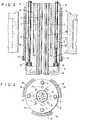
- FIG. 1 shows the basic structure of the electrode from the upper section 5 and lower section 6, which are connected by a screw nipple 1.
- the lower section 6 made of consumable or durable material is divided into a series of individual rods 20 which are bound by the nipple 1.
- the supply of the coolant e.g. Water, air or inert gas takes place via the feed channel 2, the coolant being carried out again via the return channel 3. It can be clearly seen from the figures that the cooling system is guided in the inner part 16 onto which the outer part 17 is placed.
- connection options of inner part 16 and outer part 17 can be seen as a fitting piece, optionally also with a partial thread.
- Pins 9 or the like can be guided over bores 8, which, via the spring 10, the insulating coating 4, e.g. hold on a counter bearing.
- the insulating part can additionally be fastened by brackets 14. Cooling holes 15 are shown in the outer part, while connecting jaws 18, for example. made of graphite. These can be held in brackets or pockets 19 which are attached to the outer edge of the metal shaft. This last embodiment is particularly preferred for lateral power supply.
- Gas purging channels which are not shown in the figures, can be provided between the insulating layer 4 and the upper section 5 or its inner part.
- the gas purging can cause damage to the insulating ceramic, for example via a corresponding one Pressure drop, can be easily determined.
- a certain cooling effect is possible.
- the upper section 5 and / or the nipple connection 1 or its outer surfaces can be coated with a high-temperature-resistant coating.
- the high-temperature-resistant coating can be designed to be electrically conductive or also insulating.
- the coating can also consist of a high-temperature-resistant, conductive material, in which case this material has the effect of a "heat shield” or “inert shield” to protect the underlying metal.
- a dense formation of the coating can also advantageously prevent the attack of the electrolysis media.
Landscapes
- Chemical & Material Sciences (AREA)
- Engineering & Computer Science (AREA)
- Chemical Kinetics & Catalysis (AREA)
- Electrochemistry (AREA)
- Materials Engineering (AREA)
- Metallurgy (AREA)
- Organic Chemistry (AREA)
- Electrolytic Production Of Metals (AREA)
- Secondary Cells (AREA)
- Battery Electrode And Active Subsutance (AREA)
- Electrolytic Production Of Non-Metals, Compounds, Apparatuses Therefor (AREA)
Priority Applications (6)
| Application Number | Priority Date | Filing Date | Title |
|---|---|---|---|
| EP80106579A EP0050680A1 (fr) | 1980-10-27 | 1980-10-27 | Electrode pour électrolyse ignée |
| JP56130376A JPS5776192A (en) | 1980-10-27 | 1981-08-21 | Electrode for electrolytic refining of molten substance |
| HU813130A HU183640B (en) | 1980-10-27 | 1981-10-26 | Electrode for electrolyzing melted salts |
| ES507054A ES8207594A1 (es) | 1980-10-27 | 1981-10-26 | Mejoras en los electrodos para electrolisis de metales. |
| DD81234359A DD201837A5 (de) | 1980-10-27 | 1981-10-26 | Elektrode fuer schmelzflusselektrolyse |
| NO813602A NO813602L (no) | 1980-10-27 | 1981-10-26 | Elektrode for smeltebadelektrolyse. |
Applications Claiming Priority (1)
| Application Number | Priority Date | Filing Date | Title |
|---|---|---|---|
| EP80106579A EP0050680A1 (fr) | 1980-10-27 | 1980-10-27 | Electrode pour électrolyse ignée |
Publications (1)
| Publication Number | Publication Date |
|---|---|
| EP0050680A1 true EP0050680A1 (fr) | 1982-05-05 |
Family
ID=8186858
Family Applications (1)
| Application Number | Title | Priority Date | Filing Date |
|---|---|---|---|
| EP80106579A Withdrawn EP0050680A1 (fr) | 1980-10-27 | 1980-10-27 | Electrode pour électrolyse ignée |
Country Status (6)
| Country | Link |
|---|---|
| EP (1) | EP0050680A1 (fr) |
| JP (1) | JPS5776192A (fr) |
| DD (1) | DD201837A5 (fr) |
| ES (1) | ES8207594A1 (fr) |
| HU (1) | HU183640B (fr) |
| NO (1) | NO813602L (fr) |
Cited By (1)
| Publication number | Priority date | Publication date | Assignee | Title |
|---|---|---|---|---|
| EP0092704A1 (fr) * | 1982-04-26 | 1983-11-02 | C. CONRADTY NÜRNBERG GmbH & Co. KG | Utilisation de matériaux imperméables au gaz et résistant à la corrosion et à la température comme revêtement protecteur pour la partie métallique d'électrodes combinées destinées à l'obtention de métaux par électrolyse ignée, ainsi qu'anneaux de garde obtenus à partir de ces matériaux |
Citations (2)
| Publication number | Priority date | Publication date | Assignee | Title |
|---|---|---|---|---|
| DE2425136A1 (de) * | 1973-05-25 | 1974-12-12 | Alusuisse | Schmelzflusselektrolyse mit unverbrauchbaren anoden |
| AT339061B (de) * | 1973-10-16 | 1977-09-26 | Alusuisse | Verfahren und anode zur schmelzflusselektrolyse von aluminiumoxid mit unverbrauchbaren anoden |
-
1980
- 1980-10-27 EP EP80106579A patent/EP0050680A1/fr not_active Withdrawn
-
1981
- 1981-08-21 JP JP56130376A patent/JPS5776192A/ja active Pending
- 1981-10-26 NO NO813602A patent/NO813602L/no unknown
- 1981-10-26 HU HU813130A patent/HU183640B/hu unknown
- 1981-10-26 DD DD81234359A patent/DD201837A5/de unknown
- 1981-10-26 ES ES507054A patent/ES8207594A1/es not_active Expired
Patent Citations (2)
| Publication number | Priority date | Publication date | Assignee | Title |
|---|---|---|---|---|
| DE2425136A1 (de) * | 1973-05-25 | 1974-12-12 | Alusuisse | Schmelzflusselektrolyse mit unverbrauchbaren anoden |
| AT339061B (de) * | 1973-10-16 | 1977-09-26 | Alusuisse | Verfahren und anode zur schmelzflusselektrolyse von aluminiumoxid mit unverbrauchbaren anoden |
Cited By (1)
| Publication number | Priority date | Publication date | Assignee | Title |
|---|---|---|---|---|
| EP0092704A1 (fr) * | 1982-04-26 | 1983-11-02 | C. CONRADTY NÜRNBERG GmbH & Co. KG | Utilisation de matériaux imperméables au gaz et résistant à la corrosion et à la température comme revêtement protecteur pour la partie métallique d'électrodes combinées destinées à l'obtention de métaux par électrolyse ignée, ainsi qu'anneaux de garde obtenus à partir de ces matériaux |
Also Published As
| Publication number | Publication date |
|---|---|
| NO813602L (no) | 1982-04-28 |
| HU183640B (en) | 1984-05-28 |
| ES507054A0 (es) | 1982-10-01 |
| ES8207594A1 (es) | 1982-10-01 |
| JPS5776192A (en) | 1982-05-13 |
| DD201837A5 (de) | 1983-08-10 |
Similar Documents
| Publication | Publication Date | Title |
|---|---|---|
| DE3142686C1 (de) | Kathode fuer eine Schmelzflusselektrolysezelle zur Herstellung von Aluminium | |
| DE2830490C2 (de) | Zelle für die elektrolytische Abscheidung von Alkalimetallen | |
| EP0050681B1 (fr) | Electrode pour électrolyse ignée | |
| CH629056A5 (de) | Elektrode fuer lichtbogenoefen. | |
| DE3003922C2 (de) | Anode aus dimensionsstabilen oxidkeramischen Einzelelementen | |
| EP0057012A2 (fr) | Electrode pour électrolyse ignée | |
| DE2244040C3 (de) | Elektrodenanordnung für elektrolytische Zellen | |
| EP0050679B1 (fr) | Electrode pour électrolyse ignée | |
| DD201835A5 (de) | Elektrode fuer lichtbogenoefen | |
| DE2547061B2 (de) | Vorrichtung zum Schutz von Stromzuführungszapfen an Anodenkohlen für die Schmelzflußelektrolyse von Aluminium | |
| DD201837A5 (de) | Elektrode fuer schmelzflusselektrolyse | |
| DE69432892T2 (de) | Vorrichtung für elektrisches schmelzen | |
| EP0092704B1 (fr) | Utilisation de matériaux imperméables au gaz et résistant à la corrosion et à la température comme revêtement protecteur pour la partie métallique d'électrodes combinées destinées à l'obtention de métaux par électrolyse ignée, ainsi qu'anneaux de garde obtenus à partir de ces matériaux | |
| DE2430817B2 (de) | Elektrode fuer lichtbogenoefen | |
| EP0723734A1 (fr) | Electrode de sole pour cuve metallurgique | |
| DE2643369A1 (de) | Elektrodeneinheit einer elektrischen entladeeinrichtung | |
| DE102007041329A1 (de) | Plasmabrenner mit axialer Pulvereindüsung | |
| EP0051074A1 (fr) | Electrode pour fours à arc | |
| DE867116C (de) | Gluehofen fuer Hoechsttemperaturen, vorzugsweise ueber 1400íÒC, mit elektrischer Widerstandsheizung | |
| DE1696471B1 (de) | Feuerfeste keramikelektrode zum schmelten von glas | |
| CH653201A5 (en) | Hollow electrode for feeding arc furnaces | |
| EP0074567B1 (fr) | Support d'électrode axialement déplaçable, utilisable dans l'électrolyse de bains fondus | |
| DE543138C (de) | Stromzufuehrung fuer Elektroden elektrischer OEfen | |
| DE1934267A1 (de) | Hochdruck-Entladungslampe mit gekuehlten Elektroden | |
| DE1184510B (de) | Elektrolysezelle zur Herstellung von Aluminium |
Legal Events
| Date | Code | Title | Description |
|---|---|---|---|
| PUAI | Public reference made under article 153(3) epc to a published international application that has entered the european phase |
Free format text: ORIGINAL CODE: 0009012 |
|
| AK | Designated contracting states |
Designated state(s): AT BE CH DE FR GB IT NL SE |
|
| 17P | Request for examination filed |
Effective date: 19821020 |
|
| STAA | Information on the status of an ep patent application or granted ep patent |
Free format text: STATUS: THE APPLICATION HAS BEEN WITHDRAWN |
|
| 18W | Application withdrawn |
Withdrawal date: 19840601 |
|
| RIN1 | Information on inventor provided before grant (corrected) |
Inventor name: PILBROW, MALCOLM F., DR., DIPL.-CHEM. Inventor name: ZOELLNER, GEB. MOELLER, CHRISTINE M.DR. DIPL.-CHEM Inventor name: KOZIOL, KONRAD, DIPL.-CHEM. Inventor name: ZOELLNER, DIETER H, DR. DIPL. CHEM. |