EP0057012A2 - Electrode pour électrolyse ignée - Google Patents
Electrode pour électrolyse ignée Download PDFInfo
- Publication number
- EP0057012A2 EP0057012A2 EP82100519A EP82100519A EP0057012A2 EP 0057012 A2 EP0057012 A2 EP 0057012A2 EP 82100519 A EP82100519 A EP 82100519A EP 82100519 A EP82100519 A EP 82100519A EP 0057012 A2 EP0057012 A2 EP 0057012A2
- Authority
- EP
- European Patent Office
- Prior art keywords
- jacket
- electrode according
- upper section
- electrode
- segments
- Prior art date
- Legal status (The legal status is an assumption and is not a legal conclusion. Google has not performed a legal analysis and makes no representation as to the accuracy of the status listed.)
- Withdrawn
Links
Images


Classifications
-
- H—ELECTRICITY
- H05—ELECTRIC TECHNIQUES NOT OTHERWISE PROVIDED FOR
- H05B—ELECTRIC HEATING; ELECTRIC LIGHT SOURCES NOT OTHERWISE PROVIDED FOR; CIRCUIT ARRANGEMENTS FOR ELECTRIC LIGHT SOURCES, IN GENERAL
- H05B7/00—Heating by electric discharge
- H05B7/02—Details
- H05B7/06—Electrodes
- H05B7/08—Electrodes non-consumable
-
- C—CHEMISTRY; METALLURGY
- C25—ELECTROLYTIC OR ELECTROPHORETIC PROCESSES; APPARATUS THEREFOR
- C25C—PROCESSES FOR THE ELECTROLYTIC PRODUCTION, RECOVERY OR REFINING OF METALS; APPARATUS THEREFOR
- C25C3/00—Electrolytic production, recovery or refining of metals by electrolysis of melts
- C25C3/06—Electrolytic production, recovery or refining of metals by electrolysis of melts of aluminium
- C25C3/08—Cell construction, e.g. bottoms, walls, cathodes
- C25C3/12—Anodes
-
- C—CHEMISTRY; METALLURGY
- C25—ELECTROLYTIC OR ELECTROPHORETIC PROCESSES; APPARATUS THEREFOR
- C25C—PROCESSES FOR THE ELECTROLYTIC PRODUCTION, RECOVERY OR REFINING OF METALS; APPARATUS THEREFOR
- C25C7/00—Constructional parts, or assemblies thereof, of cells; Servicing or operating of cells
- C25C7/02—Electrodes; Connections thereof
- C25C7/025—Electrodes; Connections thereof used in cells for the electrolysis of melts
-
- H—ELECTRICITY
- H05—ELECTRIC TECHNIQUES NOT OTHERWISE PROVIDED FOR
- H05B—ELECTRIC HEATING; ELECTRIC LIGHT SOURCES NOT OTHERWISE PROVIDED FOR; CIRCUIT ARRANGEMENTS FOR ELECTRIC LIGHT SOURCES, IN GENERAL
- H05B7/00—Heating by electric discharge
- H05B7/02—Details
- H05B7/06—Electrodes
- H05B7/08—Electrodes non-consumable
- H05B7/085—Electrodes non-consumable mainly consisting of carbon
-
- H—ELECTRICITY
- H05—ELECTRIC TECHNIQUES NOT OTHERWISE PROVIDED FOR
- H05B—ELECTRIC HEATING; ELECTRIC LIGHT SOURCES NOT OTHERWISE PROVIDED FOR; CIRCUIT ARRANGEMENTS FOR ELECTRIC LIGHT SOURCES, IN GENERAL
- H05B7/00—Heating by electric discharge
- H05B7/02—Details
- H05B7/10—Mountings, supports, terminals or arrangements for feeding or guiding electrodes
- H05B7/101—Mountings, supports or terminals at head of electrode, i.e. at the end remote from the arc
-
- Y—GENERAL TAGGING OF NEW TECHNOLOGICAL DEVELOPMENTS; GENERAL TAGGING OF CROSS-SECTIONAL TECHNOLOGIES SPANNING OVER SEVERAL SECTIONS OF THE IPC; TECHNICAL SUBJECTS COVERED BY FORMER USPC CROSS-REFERENCE ART COLLECTIONS [XRACs] AND DIGESTS
- Y02—TECHNOLOGIES OR APPLICATIONS FOR MITIGATION OR ADAPTATION AGAINST CLIMATE CHANGE
- Y02P—CLIMATE CHANGE MITIGATION TECHNOLOGIES IN THE PRODUCTION OR PROCESSING OF GOODS
- Y02P10/00—Technologies related to metal processing
- Y02P10/25—Process efficiency
Definitions
- the invention relates to an electrode for melt flow electrolysis made of an upper section made of metal and a replaceable lower section made of consumable or non-consumable material, which are connected to one another by a screw nipple, a clamp connection or the like, the upper section optionally comprising a cooling device and the upper section has a protective coating at least in its lower region.
- Melt flow electrolysis is to be understood in particular as methods for the extraction of metals, such as Al, Mg, Na, Li etc., which cannot be separated from aqueous solutions due to the negative potential.
- combination electrodes which consist of an electrode holder with attached active part, for operation in melt flow electrolysis is unknown.
- the metallic electrode holder is not only used for mechanical attachment of the active part, ' but also as a power supply.
- D E -OS 24 25 136 already non-consumable anodes for the S chmelzflußelektrolyse known in which a layer of slag on the exposed power supply and the unprotected anode is formed by local cooling or uncooled anode assembly through a to the electrolyte-resistant, electrically insulating Material is shielded.
- the object of the present invention is to provide electrode constructions with a long service life and a low current and voltage drop in the feed line, which are as prone to failure as possible, but which are also easy to manufacture and repair.
- the electrode construction should also have certain emergency running properties if the active part of the electrode is destroyed, used up or passivated.
- an electrode of the type mentioned at the outset which is characterized in that the protective coating constitutes a detachably fitted jacket 4 made of mechanically and chemically resistant material which is electrically conductive.
- the jacket it is possible to keep the jacket approximately in the range of the electrical potential of the electrode. This can be done, for example, by directly placing the jacket on the upper section made of metal, hereinafter also referred to as a metal shaft, or by electrically conductive connection with the latter and durability compared to the electrolysis medium or the materials developed here. In this case, materials can be selected which have good electrical conductivity. It is particularly preferred if the specific electrical resistance is less than 100 ⁇ mm 2 / m.
- the upper section of the electrode thus has a first, outer, mechanically resistant, temperature-resistant outer shell, which is detachably attached. This absorbs the mechanical, thermal and corrosive stresses that can occur during the melt flow electrolysis and thereby ensures the continuation of the electrode process via the inner core which is connected to the power supply.
- the jacket can be carried by a homogeneous or grid-like intermediate layer on the metal shaft, which is not an inseparable or poorly detachable connection with the coat results.
- the intermediate layer can be electrically conductive, which is particularly preferred, or it can be electrically insulating. The choice of elastic or resilient intermediate layers, which are particularly good at taking account of the vibrations and other mechanical stresses of the electrode, has proven to be particularly favorable.
- the jacket can also have a cooling system. So cooling grooves for gas cooling, but also a coolant circuit can be provided.
- the jacket can represent, for example, a double-walled tube in which gas, e.g. B. air, nitrogen or argon, respectively. Liquid is fed in and out. Obviously, this can be done in a variety of ways, for example by axially or helically guiding cooling channels, etc.
- the jacket can be a tube surrounding the upper section made of refractory, high-temperature steel, with cooling channels running through it, the steel tube on the metal shaft who prefers consists of copper or other highly conductive metal or metal alloy, is stored.
- the jacket section drawn around the end face can conductively touch the consumable lower section, which generally consists of carbon material, such as graphite or electrically conductive ceramic material, such as tin oxide, or can be only a short distance therefrom.
- the jacket can have an insulating insert, for example a ceramic ring, etc., for additional protection of the end face of the upper section to the "active section" of the electrode.
- An intermediate layer can advantageously also be provided between the jacket and the metal of the upper section. Depending on whether the outer jacket is to be kept at the potential of the electrode or at ground potential, this intermediate layer can be electrically conductive or electrically insulating.
- the intermediate layer can be used as an alternative or in addition to the mounts or spacers otherwise provided for even better support of the jacket on the metal shaft.
- the intermediate layer can cover the entire space between the jacket and metal of the upper section, but alternatively it can also only be present in partial areas. It is not only to apply the intermediate layer in grid form, but with particular advantage in mind to continuously support the jacket in areas of particular stress, if necessary.
- a particularly favorable embodiment of the invention is directed towards the provision of materials which have elastic or resilient properties. As such materials, e.g. As carbon fibers, carbon cords, carbon powder, graphite foils, granular graphite, copper braid or a combination thereof, these materials result in an electrically conductive intermediate layer.
- the intermediate layer to be electrically insulating, for example non-conductive ceramic fibers, glass fibers, etc. can be used.
- Resins which can ensure an elastic fit of the jacket on the metal shaft of the combination electrode, can serve as a further favorable material for the intermediate layer.
- Usable synthetic resins are e.g. B. such as are known for example for the manufacture of the insulating parts of high-voltage switches or as a basis for printed circuits, etc. Of course, it is also possible to use combinations of such materials, which can depend on the type of jacket, the stress on the electrode and its design.
- the use of high-temperature-resistant, conductive felt or such fibers, nonwovens or fabrics is preferred, particularly in those applications where the electrode is exposed to mechanical shocks or vibrations during operation, so that it is important to intercept the outer jacket elastically and electrically what additional stabilization of the Electrode contributes.
- the jacket is formed from a plurality of elements, in particular segments.
- These can comprise a series of pipe sections, half-shells or the like, which surround at least the lower area of the upper section of the electrode up to the area of the screw nipple, possibly beyond.
- the jacket can surround the so-called "three-phase area", i. H. the area exposed to the electrolysis medium in the area of the transition to the ambient atmosphere.
- the use of essentially tubular sections is particularly preferred. It may be advantageous if the individual segments are seated one on top of the other, so that if an underlying segment breaks or fails, the upper segments can slide into the zone of particular stress. In such a case, it is expedient to store only the lowest segment of the jacket on the metal shaft or on brackets or intermediate pieces, so that the segments above are freely movable.
- the jacket consists of segments, wherein each individual segment can be connected to the metal of the upper section via a thread.
- This arrangement also makes it possible to successively close the segments or tube sections of the jacket from bottom to top by means of a corresponding screwing movement move.
- the purpose of this is to move the lower segments, which are subject to greater wear and tear, which are already somewhat attacked but are still suitable for protecting the upper part of the metal shaft, and which have been added from below or have been previously attached to the upper part of the metal shaft Arrange segments or pipe sections on the lower part of the metal shaft.
- the thread only has to be suitably trained.
- the advantage of this measure is that the pipe sections or segments of the jacket can be used as long as possible and in a material-saving manner.
- the profiling of the one segment has at least one annular elevation which engages in an annular groove of the profiling of the adjacent segment. It has proven particularly suitable if the annular elevation of one segment and the annular groove of the adjacent segment have an approximately trapezoidal cross section.
- the individual segments are advantageously designed such that recesses are formed on their inner surface. These are particularly ring-shaped.
- the materials of the electrically conductive or the electrically insulating intermediate layer can be in the annular recesses - be introduced. Carbon fibers or felts, cords, if appropriate in combination with graphite foils, are advantageously introduced into these recesses, as a result of which the individual segments connected to the core via a thread are supported in a particularly elastic manner.
- Such embodiments of the jacket provided according to the invention are shown in FIGS. 4 to 6, to which express reference is already made here for this purpose.
- the jacket or its segments prefferably have a coating which is resistant to high temperatures.
- an electrode is particularly preferred in which, in the lower region of the metal shaft to which the active part is connected, the jacket is divided into individual segments, which are preferably made of graphite, and where appropriate between the graphite segments and the metal shaft by inserting conductive tissue or felt has been buffered or has been made gas-tight or liquid-tight by the introduction of sealing materials.
- a refractory compound which is applied, for example, by spraying, can adjoin the segments in the direction of the upper part of the metal shaft.
- An additional liability of the refractory mass can result from the introduction of brackets, e.g. B. announced ' welded hexagonal lattice pieces, etc., result. It is usually ensured that the brackets are covered by the refractory layer.
- the design of the protective cover according to the invention a particularly effective protection of the transition area of the (water) cooled metal shaft to the active part, for. B. made of graphite.
- the inventive design of the jacket as a detachable molded part which is electrically conductive and can be segmented, takes the thermal alternating stress and the mechanical load, but in particular also the vibration, particularly well into account.
- the choice of electrically conductive materials with good mechanical stability and in particular their constructive design and attachment to the metal shaft results in a high level of operational reliability and the service life of the combination electrode.
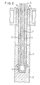
- the cooling medium for. B. water or air
- the cooling medium also enters a chamber inside the screw nipple 1.
- the upper section 5, usually made of copper or another highly conductive metal, is surrounded by a ring-shaped jacket 4, which surrounds the lower region of the metal shaft at a distance. It is screwed onto the metal shaft via a threaded washer 40. In the lower region of the metal shaft, the jacket 4 is kept at a distance via an intermediate piece 7, to which a further threaded washer 40 is connected.
- jaws 18 of the power supply are shown, while cooling bores 15 are provided in the metal shaft.
- Fig. 2 the jacket is shown as a fitting beginning under the power supply 18, which is additionally screwed in its upper area with a thread to the inner metal shaft which carries the cooling system 2, 3.
- a highly conductive metal eg. B. copper
- the electrical conductivity of the outer jacket can be lower than that of the inner metal shaft, since its conductivity only has to serve to impart emergency running properties.
- a buffering material such as felt, nonwovens made of ceramic fiber or carbon, or graphite foil, into the recess between the inner metal shaft and the outer jacket, but this is not shown in FIG. 2.
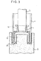
- the electrically conductive jacket 4 is in turn designed as a tube which, in addition to a fastening to the shaft 5 (not shown), is also supported in a recess in the active part 6.
- a high-temperature-resistant mass 25 is introduced into the recess, which - after the electrode has been designed - can be electrically conductive or insulating.
- the 4 shows the particularly preferred design of individual segments of the casing 4.
- the individual segments are screwed to the outer wall of the metal shaft 5 by means of a thread.
- the segments are trapezoidal on the end faces and thus create a labyrinth seal.
- Carbon cords and also carbon felts 26 are introduced into recesses on the inner surface of the segments.
- the design of the jacket 4 or the individual segments can be different.
- FIG. 5 shows a segment which is screwed onto the metal shaft 5 by means of a centrally attached thread.
- elastic or resilient materials for.
- a graphite foil 31 can also be provided.
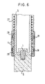
- Fig. 6 again slightly differently shaped profiles are shown, in the interior of which, or via holes 28, injected synthetic resin material can be introduced and condensed in situ.
- a refractory mass is sprayed onto hexagrids 27.
- the jacket which is electrically conductive, in particular those with a high melting point and high heat resistance, but also resistance to temperature changes can be used.
- the materials can be made from high-temperature steel, metals, e.g. B. aluminum and in particular their alloys can be selected. In some applications, carbides, nitrides or oxides of such metals can also be suitable.
- carbon material and in particular graphite can also be used, especially if it is impregnated and / or due to the special design described in individual segments and advantageously by means of an elastic intermediate layer, but also, if appropriate, by dimensioning it to a mechanical stress is particularly conditioned.
Landscapes
- Engineering & Computer Science (AREA)
- Chemical & Material Sciences (AREA)
- Physics & Mathematics (AREA)
- Plasma & Fusion (AREA)
- Organic Chemistry (AREA)
- Electrochemistry (AREA)
- Materials Engineering (AREA)
- Metallurgy (AREA)
- Chemical Kinetics & Catalysis (AREA)
- Discharge Heating (AREA)
- Vertical, Hearth, Or Arc Furnaces (AREA)
- Furnace Details (AREA)
- Resistance Heating (AREA)
- Electrolytic Production Of Metals (AREA)
- Electrodes For Compound Or Non-Metal Manufacture (AREA)
- Electric Stoves And Ranges (AREA)
- Liquid Crystal Substances (AREA)
Applications Claiming Priority (2)
| Application Number | Priority Date | Filing Date | Title |
|---|---|---|---|
| DE19813102776 DE3102776A1 (de) | 1981-01-28 | 1981-01-28 | Elektrode fuer lichtbogenoefen |
| DE3102776 | 1981-01-28 |
Publications (2)
| Publication Number | Publication Date |
|---|---|
| EP0057012A2 true EP0057012A2 (fr) | 1982-08-04 |
| EP0057012A3 EP0057012A3 (fr) | 1982-09-01 |
Family
ID=6123500
Family Applications (2)
| Application Number | Title | Priority Date | Filing Date |
|---|---|---|---|
| EP81110447A Withdrawn EP0056862A3 (fr) | 1981-01-28 | 1981-12-15 | Electrode pour four à arc |
| EP82100519A Withdrawn EP0057012A3 (fr) | 1981-01-28 | 1982-01-26 | Electrode pour électrolyse ignée |
Family Applications Before (1)
| Application Number | Title | Priority Date | Filing Date |
|---|---|---|---|
| EP81110447A Withdrawn EP0056862A3 (fr) | 1981-01-28 | 1981-12-15 | Electrode pour four à arc |
Country Status (26)
| Country | Link |
|---|---|
| US (2) | US4474613A (fr) |
| EP (2) | EP0056862A3 (fr) |
| JP (2) | JPS57188692A (fr) |
| KR (1) | KR860000053B1 (fr) |
| AU (1) | AU549057B2 (fr) |
| BR (1) | BR8200469A (fr) |
| CA (2) | CA1190578A (fr) |
| CS (1) | CS249120B2 (fr) |
| DD (1) | DD202361A5 (fr) |
| DE (1) | DE3102776A1 (fr) |
| DK (1) | DK35982A (fr) |
| EG (1) | EG14976A (fr) |
| ES (1) | ES509918A0 (fr) |
| FI (1) | FI820125L (fr) |
| GB (1) | GB2096438B (fr) |
| GR (1) | GR75186B (fr) |
| HU (1) | HU183789B (fr) |
| IN (1) | IN155793B (fr) |
| MX (1) | MX152510A (fr) |
| NO (2) | NO820079L (fr) |
| NZ (1) | NZ199230A (fr) |
| PL (1) | PL234966A1 (fr) |
| PT (1) | PT74344B (fr) |
| RO (1) | RO88576A (fr) |
| YU (1) | YU18982A (fr) |
| ZA (1) | ZA82247B (fr) |
Families Citing this family (13)
| Publication number | Priority date | Publication date | Assignee | Title |
|---|---|---|---|---|
| DE3135912A1 (de) * | 1981-09-10 | 1983-03-24 | C. Conradty Nürnberg GmbH & Co KG, 8505 Röthenbach | Axial verschiebbarer elektrodenhalter zum einsatz bei der schmelzflusselektrolyse |
| ZA832153B (en) * | 1982-04-26 | 1983-12-28 | Arc Tech Syst Ltd | Protective coating of temperature resistant materials for the metal shaft of combination electrodes for the electric steel production |
| DE3215537A1 (de) * | 1982-04-26 | 1983-10-27 | C. Conradty Nürnberg GmbH & Co KG, 8505 Röthenbach | Verwendung von temperatur- und korosionsbestaendigen gasdichten materialien als schutzueberzug fuer den metallteil von kombinationselektroden fuer die schmelzflusselektrolyse zur gewinnung von metallen, sowie hieraus gebildete schutzringe |
| DE3319389C2 (de) * | 1983-05-26 | 1987-03-05 | Mannesmann AG, 4000 Düsseldorf | Elektrode für Lichtbogenöfen |
| EP0135473A1 (fr) * | 1983-08-13 | 1985-03-27 | Arc Technologies Systems, Ltd. | Assemblage d'électrode pour fours à arc |
| DE3440073A1 (de) * | 1984-11-02 | 1986-05-07 | Didier-Werke Ag, 6200 Wiesbaden | Graphitelektrode fuer einen lichtbogenofen |
| US4688671A (en) * | 1986-11-07 | 1987-08-25 | Whitmor Manufacturing Co., Inc. | Garment bag adapted for use with ventilated shelving |
| CA2071235C (fr) * | 1991-07-26 | 2004-10-19 | Gerald L. Bauer | Anode pour cellule electrolytique utilisee pour la preparation du fluor |
| DE69428720T2 (de) * | 1993-09-03 | 2002-07-11 | Minnesota Mining And Mfg. Co., Saint Paul | Fluor-Zelle |
| US5912916A (en) * | 1995-05-01 | 1999-06-15 | Alabama Power Company | Electric furnace with insulated electrodes and process for producing molten metals |
| RU2158062C1 (ru) * | 1999-07-28 | 2000-10-20 | Открытое акционерное общество "Институт Гипроникель" | Способ защиты нерасходуемого электрода в шлаковом расплаве |
| CN115540592B (zh) * | 2022-09-16 | 2025-05-23 | 贵州固鑫新材料有限公司 | 一种棕刚玉电弧炉节能短网系统 |
| CN116043280A (zh) * | 2023-02-17 | 2023-05-02 | 三河市日盛机械制造有限公司 | 一种铅基合金电解炉 |
Family Cites Families (20)
| Publication number | Priority date | Publication date | Assignee | Title |
|---|---|---|---|---|
| GB190904175A (en) * | 1909-02-20 | 1909-11-11 | Marcus Ruthenburg | Improvements in or relating to Electrodes for Electric Furnaces. |
| US1982009A (en) * | 1931-11-30 | 1934-11-27 | Paul E Mckinney | Means for electroplating the interior surfaces of hollow articles |
| DE1293360B (de) * | 1962-12-20 | 1969-04-24 | Leybold Heraeus Gmbh & Co Kg | Einrichtung zur Halterung und Stromversorgung einer Abschmelzelektrode in einem Lichtbogenofen |
| FR1418153A (fr) * | 1964-10-05 | 1965-11-19 | Siderurgie Fse Inst Rech | Dispositif de passage d'électrodes dans un four électrique |
| US3385987A (en) * | 1966-10-24 | 1968-05-28 | Westinghouse Electric Corp | Electrode for an arc furnace having a fluid cooled arcing surface and a continuouslymoving arc thereon |
| SE391348B (sv) * | 1971-09-07 | 1977-02-14 | Aluminum Co Of America | Elektrodanordning for anvendning i korrosiv atmosfer |
| FR2176546A1 (en) * | 1972-03-23 | 1973-11-02 | Siderurgie Fse Inst Rech | Composite furnace electrode - esp for steel prodn |
| CH592163A5 (fr) * | 1973-10-16 | 1977-10-14 | Alusuisse | |
| DE2725537A1 (de) * | 1977-06-06 | 1978-12-14 | Korf Stahl | Elektrode fuer lichtbogenoefen |
| CH625560A5 (fr) * | 1977-12-16 | 1981-09-30 | Alusuisse | |
| US4145564A (en) * | 1978-01-30 | 1979-03-20 | Andrew Dennie J | Non-consumable electrode with replaceable graphite tip |
| DE2845367C2 (de) * | 1978-10-18 | 1981-01-22 | Korf & Fuchs Syst Tech | FlUssigkeitsgekühlte Halterung für die Spitze einer Elektrode eines Lichtbogenschmelzofens |
| US4287381A (en) * | 1978-12-19 | 1981-09-01 | British Steel Corporation | Electric arc furnace electrodes |
| DE2910811C2 (de) * | 1979-02-16 | 1982-02-18 | Schweizerische Aluminium AG, 3965 Chippis | Stromzuleitereinrichtung für Elektroden |
| SE431443B (sv) * | 1979-03-23 | 1984-02-06 | Bulten Kanthal Ab | Elektrod for uppvermning av glasmassa |
| US4280891A (en) * | 1979-05-17 | 1981-07-28 | Amax Magnesium Corporation | Electrode assembly for melt cell |
| CH642402A5 (de) * | 1979-12-18 | 1984-04-13 | Alusuisse | Anode aus dimensionsstabilen oxidkeramischen einzelelementen. |
| EP0051074A1 (fr) * | 1980-10-27 | 1982-05-12 | Arc Technologies Systems, Ltd. | Electrode pour fours à arc |
| DE3071711D1 (en) * | 1980-10-27 | 1986-09-25 | Arc Tech Syst Ltd | Electrode for arc furnaces |
| EP0050683A1 (fr) * | 1980-10-27 | 1982-05-05 | Arc Technologies Systems, Ltd. | Electrode pour fours à arc |
-
1981
- 1981-01-28 DE DE19813102776 patent/DE3102776A1/de not_active Withdrawn
- 1981-12-10 NZ NZ199230A patent/NZ199230A/en unknown
- 1981-12-15 EP EP81110447A patent/EP0056862A3/fr not_active Withdrawn
- 1981-12-17 AU AU78593/81A patent/AU549057B2/en not_active Expired - Fee Related
-
1982
- 1982-01-12 NO NO820079A patent/NO820079L/no unknown
- 1982-01-14 ZA ZA82247A patent/ZA82247B/xx unknown
- 1982-01-15 FI FI820125A patent/FI820125L/fi not_active Application Discontinuation
- 1982-01-18 IN IN74/CAL/82A patent/IN155793B/en unknown
- 1982-01-18 CA CA000394320A patent/CA1190578A/fr not_active Expired
- 1982-01-21 GR GR67079A patent/GR75186B/el unknown
- 1982-01-22 HU HU82185A patent/HU183789B/hu unknown
- 1982-01-22 KR KR8200274A patent/KR860000053B1/ko not_active Expired
- 1982-01-25 EG EG8229A patent/EG14976A/xx active
- 1982-01-25 US US06/342,488 patent/US4474613A/en not_active Expired - Fee Related
- 1982-01-26 US US06/342,813 patent/US4442525A/en not_active Expired - Fee Related
- 1982-01-26 EP EP82100519A patent/EP0057012A3/fr not_active Withdrawn
- 1982-01-27 PT PT74344A patent/PT74344B/pt unknown
- 1982-01-27 DK DK35982A patent/DK35982A/da not_active Application Discontinuation
- 1982-01-27 GB GB8202360A patent/GB2096438B/en not_active Expired
- 1982-01-27 NO NO820249A patent/NO156904C/no unknown
- 1982-01-27 YU YU00189/82A patent/YU18982A/xx unknown
- 1982-01-27 MX MX191166A patent/MX152510A/es unknown
- 1982-01-27 RO RO82106455A patent/RO88576A/fr unknown
- 1982-01-27 CS CS82575A patent/CS249120B2/cs unknown
- 1982-01-27 CA CA000395059A patent/CA1179638A/fr not_active Expired
- 1982-01-28 BR BR8200469A patent/BR8200469A/pt unknown
- 1982-01-28 JP JP57012493A patent/JPS57188692A/ja active Pending
- 1982-01-28 JP JP57012520A patent/JPS57143289A/ja active Pending
- 1982-01-28 DD DD82237044A patent/DD202361A5/de unknown
- 1982-01-28 ES ES509918A patent/ES509918A0/es active Granted
- 1982-02-05 PL PL23496682A patent/PL234966A1/xx unknown
Also Published As
Similar Documents
| Publication | Publication Date | Title |
|---|---|---|
| DE2910811C2 (de) | Stromzuleitereinrichtung für Elektroden | |
| EP0056862A2 (fr) | Electrode pour four à arc | |
| CH629056A5 (de) | Elektrode fuer lichtbogenoefen. | |
| EP0151415B1 (fr) | Four à arc à courant continu ou poche de coulée à arc à courant continu | |
| EP0050681B1 (fr) | Electrode pour électrolyse ignée | |
| EP0050682B1 (fr) | Electrode pour fours à arc | |
| DE2740340A1 (de) | Verfahren zur verminderung der waermeabstrahlung aus einer zelle zur elektrolytischen reduktion von aluminiumoxid | |
| DE2244040C3 (de) | Elektrodenanordnung für elektrolytische Zellen | |
| EP3472373B1 (fr) | Bloc cathodique présentant une géométrie à rainure | |
| DE4335065C2 (de) | Bodenelektrode für ein mit Gleichstrom betriebenes metallurgisches Gefäß | |
| EP0050679B1 (fr) | Electrode pour électrolyse ignée | |
| DE4129756C2 (de) | Metallurgisches Gefäß für eine Gleichstromlichtbogeneinrichtung | |
| EP0092704A1 (fr) | Utilisation de matériaux imperméables au gaz et résistant à la corrosion et à la température comme revêtement protecteur pour la partie métallique d'électrodes combinées destinées à l'obtention de métaux par électrolyse ignée, ainsi qu'anneaux de garde obtenus à partir de ces matériaux | |
| DE3142428A1 (de) | Elektrode fuer lichtbogenoefen | |
| AT406239B (de) | Wassergekühlte kokille für das stranggiessen oder elektroschlacke-umschmelzen | |
| EP0074567B1 (fr) | Support d'électrode axialement déplaçable, utilisable dans l'électrolyse de bains fondus | |
| EP0063711B1 (fr) | Electrode pour four à arc et son utilisation | |
| DE3135960A1 (de) | Axial verschiebbarer elektrodenhalter zum einsatz bei der elektrostahlerzeugung | |
| DE3144437A1 (de) | Elektrodenhalter fuer lichtbogenoefen | |
| DE69131620T2 (de) | Elektroofen | |
| DE3506023A1 (de) | Elektrodenverbindung | |
| DE3223222C2 (de) | Elektrolysezelle zum Gewinnen von Aluminium | |
| DE102006037561A1 (de) | Hochstromelektrode | |
| DD202363A5 (de) | Elektrode fuer lichtbogenoefen und verfahren zu deren verwendung | |
| DD201837A5 (de) | Elektrode fuer schmelzflusselektrolyse |
Legal Events
| Date | Code | Title | Description |
|---|---|---|---|
| PUAI | Public reference made under article 153(3) epc to a published international application that has entered the european phase |
Free format text: ORIGINAL CODE: 0009012 |
|
| PUAL | Search report despatched |
Free format text: ORIGINAL CODE: 0009013 |
|
| AK | Designated contracting states |
Designated state(s): CH DE FR GB IT |
|
| AK | Designated contracting states |
Designated state(s): CH DE FR GB IT |
|
| 17P | Request for examination filed |
Effective date: 19830201 |
|
| STAA | Information on the status of an ep patent application or granted ep patent |
Free format text: STATUS: THE APPLICATION HAS BEEN WITHDRAWN |
|
| 18W | Application withdrawn |
Withdrawal date: 19850823 |
|
| RIN1 | Information on inventor provided before grant (corrected) |
Inventor name: ZOELLNER, CHRISTINE, DR.DIPL.-CHEM. Inventor name: LAUTERBACH-DAMMLER, INGE, DR. Inventor name: KOZIOL, KONRAD, DIPL.-CHEM. Inventor name: RITTMANN, FRIEDRICH Inventor name: ZOELLNER, DIETER H., DR. |