EP0050954A1 - Tiefbohrer - Google Patents
Tiefbohrer Download PDFInfo
- Publication number
- EP0050954A1 EP0050954A1 EP81304896A EP81304896A EP0050954A1 EP 0050954 A1 EP0050954 A1 EP 0050954A1 EP 81304896 A EP81304896 A EP 81304896A EP 81304896 A EP81304896 A EP 81304896A EP 0050954 A1 EP0050954 A1 EP 0050954A1
- Authority
- EP
- European Patent Office
- Prior art keywords
- tubular member
- debris
- cutting head
- elongate
- boring
- Prior art date
- Legal status (The legal status is an assumption and is not a legal conclusion. Google has not performed a legal analysis and makes no representation as to the accuracy of the status listed.)
- Withdrawn
Links
- 239000012530 fluid Substances 0.000 claims description 23
- 230000004888 barrier function Effects 0.000 claims description 6
- 230000004323 axial length Effects 0.000 claims description 4
- 238000012546 transfer Methods 0.000 claims description 4
- 238000005086 pumping Methods 0.000 abstract description 5
- 238000011161 development Methods 0.000 abstract description 4
- 238000007689 inspection Methods 0.000 abstract description 4
- 238000005553 drilling Methods 0.000 description 12
- 238000000034 method Methods 0.000 description 7
- 239000007788 liquid Substances 0.000 description 5
- 238000009412 basement excavation Methods 0.000 description 4
- XLYOFNOQVPJJNP-UHFFFAOYSA-N water Substances O XLYOFNOQVPJJNP-UHFFFAOYSA-N 0.000 description 4
- 230000009471 action Effects 0.000 description 3
- 230000008878 coupling Effects 0.000 description 3
- 238000010168 coupling process Methods 0.000 description 3
- 238000005859 coupling reaction Methods 0.000 description 3
- 230000018109 developmental process Effects 0.000 description 3
- 238000012423 maintenance Methods 0.000 description 3
- 239000000463 material Substances 0.000 description 3
- 238000013461 design Methods 0.000 description 2
- 238000000605 extraction Methods 0.000 description 2
- 238000000227 grinding Methods 0.000 description 2
- 238000003801 milling Methods 0.000 description 2
- 230000008569 process Effects 0.000 description 2
- 238000012216 screening Methods 0.000 description 2
- 238000000926 separation method Methods 0.000 description 2
- 239000007787 solid Substances 0.000 description 2
- 244000233952 Polygonum bistorta Species 0.000 description 1
- 230000004308 accommodation Effects 0.000 description 1
- 230000003466 anti-cipated effect Effects 0.000 description 1
- 230000001174 ascending effect Effects 0.000 description 1
- 230000015572 biosynthetic process Effects 0.000 description 1
- 238000010276 construction Methods 0.000 description 1
- 230000000694 effects Effects 0.000 description 1
- 230000007613 environmental effect Effects 0.000 description 1
- 230000007717 exclusion Effects 0.000 description 1
- 230000005484 gravity Effects 0.000 description 1
- 238000009434 installation Methods 0.000 description 1
- 238000005065 mining Methods 0.000 description 1
- 238000012544 monitoring process Methods 0.000 description 1
- 239000002245 particle Substances 0.000 description 1
- 230000009467 reduction Effects 0.000 description 1
- 230000001105 regulatory effect Effects 0.000 description 1
- 230000008439 repair process Effects 0.000 description 1
- 238000005096 rolling process Methods 0.000 description 1
- 238000007790 scraping Methods 0.000 description 1
- 238000007789 sealing Methods 0.000 description 1
- 238000007493 shaping process Methods 0.000 description 1
- 230000003019 stabilising effect Effects 0.000 description 1
- 230000003068 static effect Effects 0.000 description 1
- 230000002459 sustained effect Effects 0.000 description 1
- 238000004804 winding Methods 0.000 description 1
- 230000003245 working effect Effects 0.000 description 1
Images





Classifications
-
- E—FIXED CONSTRUCTIONS
- E21—EARTH OR ROCK DRILLING; MINING
- E21B—EARTH OR ROCK DRILLING; OBTAINING OIL, GAS, WATER, SOLUBLE OR MELTABLE MATERIALS OR A SLURRY OF MINERALS FROM WELLS
- E21B4/00—Drives for drilling, used in the borehole
- E21B4/16—Plural down-hole drives, e.g. for combined percussion and rotary drilling; Drives for multi-bit drilling units
-
- E—FIXED CONSTRUCTIONS
- E21—EARTH OR ROCK DRILLING; MINING
- E21B—EARTH OR ROCK DRILLING; OBTAINING OIL, GAS, WATER, SOLUBLE OR MELTABLE MATERIALS OR A SLURRY OF MINERALS FROM WELLS
- E21B7/00—Special methods or apparatus for drilling
- E21B7/003—Drilling with mechanical conveying means
-
- E—FIXED CONSTRUCTIONS
- E21—EARTH OR ROCK DRILLING; MINING
- E21B—EARTH OR ROCK DRILLING; OBTAINING OIL, GAS, WATER, SOLUBLE OR MELTABLE MATERIALS OR A SLURRY OF MINERALS FROM WELLS
- E21B7/00—Special methods or apparatus for drilling
- E21B7/28—Enlarging drilled holes, e.g. by counterboring
-
- E—FIXED CONSTRUCTIONS
- E21—EARTH OR ROCK DRILLING; MINING
- E21D—SHAFTS; TUNNELS; GALLERIES; LARGE UNDERGROUND CHAMBERS
- E21D1/00—Sinking shafts
- E21D1/03—Sinking shafts mechanically, e.g. by loading shovels or loading buckets, scraping devices, conveying screws
- E21D1/06—Sinking shafts mechanically, e.g. by loading shovels or loading buckets, scraping devices, conveying screws with shaft-boring cutters
Definitions
- This invention relates to apparatus for making holes in the ground particularly but not exclusively for mining purposes.
- the apparatus of the invention is particularly valuable in circumstances where it is not possible to provide prior access in the form of, for example, a smaller diameter hole (known as a pilot hole) drilled on the same line before the main hole in order to connect with existing underground workings for the purpose of disposing of debris generated by the main boring operation.
- a pilot hole Such a prior drilling is sometimes referred to as a pilot hole.
- Drilling without such prior access is commonly referred to as "blind boring” and poses difficult problems in removing debris generated in the process, particularly in the case of large-diameter holes such as those which are to be used as mineshafts.
- blind boring In the absence of a pilot hole unexpected ground conditions such as unstable, discontinuous, or water-logged strata may be encountered, demanding special treatment, such as grouting or high- capacity pumping, and therefore requiring access for special treatment equipment to the ground beneath the main boring machine.
- Existing methods for blind bole boring without the use of drilling fluids include boring tools incorporating mechanical means for removing debris from the cut face immediately beneath the boring head, such as chain conveyors adapted to scrape debris from the face to lift it through a small height and to deliver it to a main conveying system, which may be in the form of hoisted buckets or a pneumatic elevator, for removal to the surface.
- mechanical means are not easily accommodated in the confines of a boring tool structure, tending to compete with the space required for the cutting devices and their supporting structures; and they are difficult to control and to power, being located in a rotating head. They are also vulnerable to damage from the large forces employed to propel and rotate the boring head particularly in the event of debris accumulating or jamming in the bottom of the excavation.
- cutters 70 or 122 are provided at the tip of the apparatus ahead of the main cutters 65 or 124. These serve to form a vertical rim D which in effect constitutes a shallow pilot bore. In this arrangement, the cutters 70 or 122 act as a downward continuation of the main cutters as is clear from the drawings and thus there is no real axial separation between the main cutters and the pilot cutters.
- the accuracy of the main borer is unlikely to be better than the accuracy of the pilot bore unless means are provided for adjusting the one bore relative to the other. Such means tend to be complicated and difficult to accommodate in the confines and environmental conditions of a main boring head.
- An object of the present invention is to provide apparatus for the sinking of shafts which does not require the preliminary sinking of a separate pilot bore and which is relatively simple to control and to power.
- Another object of the invention is to provide such apparatus in which there is internal space available which permits the introduction of auxiliary equipment such as grouting equipment into the interior of the apparatus.
- apparatus for boring holes in the ground which comprises a first cutting head carried by an elongate tubular member; a second, annular cutting head located co-axially with the first cutting head; and means, externally carried by said elongate tubular member, for collecting debris produced in the course of a hole boring operation.
- the debris collecting means can be in the form of one or more collars located about the elongate tubular member which, when the apparatus is in use, co-operate with the side walls of the bore which is being formed so as to collect debris which then enters a port provided in the wall of the elongate tubular member at the level of the collar or which falls to the bottom of the pilot hole for collection there.
- the collar can have a conical upper section which acts.to comminute debris as it falls downwardly into the progressively tighter nip formed by co-operation of the' conical section of the collar and the sidewall of the bore.
- the debris collecting means can be in the form of an external guideway, e.g. a helical ledge (which can be termed a scroll), provided on the surface of the elongate tubular member.
- the tubular member is preferably hollow.
- apparatus for boring holes in the ground which comprises a first cutting head mounted on an elongate hollow tubular member; a second, annular cutting head located co-axially with the first cutting head; and means for conveying debris along the external surface of said elongate hollow tubular member to a port or window communicating with the interior of said elongate hollow tubular member.
- the means for conveying debris is in the form of a helical ledge secured to the external surface of the elongate hollow tubular member.
- the first cutting head acts as a pilot boring tool for the main cutting head (i.e. the second, annular cutting head in the above terminology).
- apparatus for boring holes in the ground which comprises a first cutting head mounted on an elongate hollow tubular member and serving to form a pilot hole; a second, annular cutting head located or locatable co-axially with the first cutting head and spaced axially therefrom and serving to form the hole proper; and means for removing debris which comprises (i) a helical ledge formed on the outside of at least a part of the elongate hollow tubular member, and (ii) a window formed in the body of said elongate hollow tubular member adjacent the upper end of said helical ledge.
- the helical ledge can continue downwardly from the elongate hollow tubular member so as to girdle the surface of the first cutting head.
- the debris removal means also serves to collect debris from the second, annular cutting head.
- This can be achieved by provision of a barrier adjacent the window providing access to the interior of the hollow tubular member whereby debris falls onto the barrier and from there passes through said window.
- the barrier can be dispensed with if the helical ledge is able to cope with the volume of debris produced by both cutting heads: in such a case, debris from the main cutting head (i.e. the second, annular cutting head) falls down until it reaches the helical ledge, which then conveys the debris up toward the window.
- the elongate hollow tubular member is preferably a closed body except for the provision of a window (or several windows) for debris removal.
- a window or several windows
- This enables the interior thereof to act as a working space which is flexible as to its usage.
- the working space can be adapted to receive a bucket for debris entering the space via the window, although other debris removal arrangements (e.g. a pneumatic system) may be provided if required.
- the length of the elongate hollow tubular member may be fixed or variable. Preferably its axial length (or its minimum axial length) is greater than its radius. In a variable-length arrangement, extension of the tubular member may be achieved by securing together a succession of similar cylindrical sections.
- the two heads can be formed integrally or they can be separable the one from the other.
- the two heads are mutually reciprocable along their mutual axis; this allows the axial separation of the two cutting heads to be varied to give the optimum results for a given working condition.
- the spacing of the cutting heads, and the hollow interior of the first cutting head make it possible to create space for accommodating, as required, debris removal means, pumping means, grouting means, inspection means, or any other means required for assisting the progress of a boring operation.
- Such means are preferably accommodated within the interior of the hollow body on the forward end of which the first cutting head is mounted.
- the first cutting head preferably is constructed so that it can be used to cut transversely of the main axis of the apparatus, thus making it possible to perform a sideways cutting action together with the main (second) cutting head in the course of a boring operation, e.g. for adjusting the line of the bore.
- the elongate tubular member can be modified so as to be cut away over its entire length; this leaves the interior of the tubular member exposed to a substantial portion of the cut or bored earth surface within the pilot bore.
- the first cutting head can likewise be cut away over a corresponding area.
- the leading edge of the cut-away tubular member (and the leading edge of the first cutting head if this is Similarly cut away) is provided with a debris deflecting device, e.g. a plough blade or a scraper blade or a toothed (serrated) blade, the purpose of which is to prevent debris reaching the area where the first cutting head is actively cutting away material during the formation of the pilot bore.
- a suitably shaped debris collecting bucket may be provided within this space, and such a bucket preferably has a port in the sidewall thereof through which debris can pass.
- Such a bucket will generally be dimensioned so as to be a close fit within the tubular member.
- the present invention provides apparatus for boring holes in the ground, which comprises a first cutting head mounted on an elongate hollow tubular member which is cut away in part; a second, annular cutting head located co-axially with the first cutting head; and means for collecting or deflecting debris away from the first cutting head, said means being in the form of one or more blades or scrapers carried by the cut-away tubular member and optionally by the first cutting head itself.
- the invention likewise provides a combination of the apparatus just defined and a debris collecting bucket adapted to fit into the interior of the cut-away tubular member and having a port in a sidewall thereof for admitting debris.
- the invention provides, in a fifth aspect, a tool for boring holes in the ground, which comprises an annular cutting head secured to or forming part of an annular body, the central aperture of which is elongate and is adapted to receive a further functional unit.
- the further functional unit will be selected according to the use to which the tool is to be put, e.g. boring and grouting or boring and continuous monitoring of the progress of the bore.
- the first cutting head will hereinafter be referred to as the pilot head or pilot tool, while the second, annular cutting head will be referred to as the main cutting head.
- the shaft sinking apparatus comprises a main large-diameter boring head 1.1 and a pilot head integrally formed of an elongate hollow tubular member 1.4 and a cutting head 1.14.
- the main head 1.1 is equipped with cutting tools 1.2 and is of a a generally frusto-conical form with a semi-vertical angle (i.e. the angle between the axis of the cone and the wall of the cone measured in a plane containing the axis) chosen to allow debris produced by the cutting tools 1.2 to move under the influence of gravity towards the centre of the bore, propelled if necessary by suitably orientated plough blades 1.3 or similar means.
- the central portion of the main head 1.1 is extended in the boring direction by the tubular member 1.4.
- the head 1.14 carries cutters 1.5 for boring in the axial direction, while side-cutters 1.6 to facilitate transverse, i.e. sideways, movement when required for adjusting the line of bore are carried on the external wall of the elongate hollow tubular member 1.4.
- a debris collecting device in the form of a helical ledge or scroll 1.7 is likewise provided on the external wall of the member 1.4.
- the scroll serves to lift debris from the pilot bore upwardly towards the main bore whence it may fall, or be propelled, through windows 1.8 into the hollow interior of the pilot tool 1. 4 . Debris from the main cutters 1.2 also passes through the windows 1.8 after falling downwardly to a collecting ledge 1.15.
- Retractable chutes 1.9 are provided in order to minimise spillage of debris, to direct it as required, and to close the windows 1.8 when it is desirable to halt the movement of debris.
- a hoist bucket 1.10 to receive debris from the chutes 1.9 and to transport it as required either to the surface or to another debris transporting system.
- the bucket 1.10 is raised or lowered by a hoist rope 1.11 which is winched either by shaft winding equipment or by a winch carried in the body of the boring machine.
- a swivel coupling 1.12 in the rope permits the bucket 1.10 to rotate during boring without applying torsion to the main upper part of the rope 1.11.
- the body of the boring machine is provided with a hollow central core to allow passage of the bucket 1.10.
- Sealing means 1.13 are provided inside the pilot boring tool 1.4 to engage with appropriate external surfaces of the bucket 1.10 in order to minimise spillage of material entering the bucket 1.10.
- the apparatus comprises a main large-diameter boring head 2.1 substantially as described above with reference to Figure 1 and which is provided with a central axial opening extending upwardly the full height of the main boring machine.
- the cylindrical walls 2.2 of the said opening form part of, and rotate with, the main boring head 2.1.
- a hollow pilot boring tool 2.3 equipped with an external scroll or scrolls 2.4 and windows 2.5 substantially as described above with reference to Figure 1.
- the upper part of the body of the pilot boring tool is provided with a heavy collar 2.6 adapted to fit slideably in the central opening of the main boring machine in order to hold the pilot tool concentric and in axial alignment with the main boring head.
- Retractable power-operated latches 2.7 attached to the main boring head are adapted to engage with recesses in the collar 2.6 so as to cause the pilot boring tool to rotate with the main boring tool.
- the latches 2.7 may be disengaged and the pilot boring tool lifted by hoist rope 2.8 for emptying or for replacement by another tool, or to permit access for other equipment to the pilot bore.
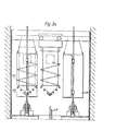
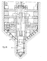
- FIG. 3a and 3b A further embodiment of the invention is shown in Figures 3a and 3b.
- a removable pilot boring tool 3.1 substantially as hereinbefore described is guided concentrically within a main boring tool 3.2 also substantially as already described, but in this embodiment the pilot boring head is adapted to be independently powered, rotated, and advanced or retracted. It is accordingly linked via a kelly bar 3.3 with a rotary-power unit 3.4 and with a cross-head 3.5 attached to rams 3.6.
- the kelly bar 3.3 is slideably linked with the rotary power unit 3.4 via keys of a rectangular cross- section in a rectangular hole arrangement so that it may receive rotary drive whilst remaining free to move up or down under the impetus of the rams 3.6.
- the upper end of the kelly bar 3.3 is attached via a swivel coupling 3.7 to a hoist rope 3.8 activated by a winch 3.9.
- the hoist rope passes over a sheave or pulley located-in the hole or shaft being bored at a height sufficient to allow the complete assembly comprising the pilot boring tool 3.1, the kelly bar 3.3, the rotating drive 3.4, the cross-head 3.5 and the rams 3.6 to be hoisted through the centre of the main boring machine in order to facilitate access to it for maintenance purposes, or to leave the pilot bore clear for the installation of pumping, inspection, drilling, grouting or other equipment.
- the same hoisting arrangement may also be employed during boring to lift the pilot boring tool 3.1 to a height at which it may be removed from the kelly bar 3.3 and transferred to a container 3.10 for hoisting to the surface where its content of drilling debris is discharged or where it may be maintained, repaired, or replaced. Meanwhile a second pilot boring tool 3.11 may be moved in from a second container 3.12 located in the upper cavity area of the main boring tool 3.2 and attached to the kelly bar 3.3 so that boring may continue during the absence of the first boring tool. In this way substantially continuous boring may be sustained by the alternating use of two pilot boring tools.
- the rotary drive 3.4 and the rams 3.6. are securely locked in position to enable them to provide the torques and forces required for boring, and are unlocked only during the hoisting operation described above.
- the direction of the pilot boring tool 3.1 coaxial with the main boring head 3.2 is maintained by a piston 3.13 which is a close slideable fit against the wall 3.14 of the central aperture of the main boring machine and is attached to the kelly bar 3.3 for which it provides guidance for the pilot boring tool 3.1.
- the kelly bar 3.3, the rotating drive 3.4, the cross-head 3.5 and the rams 3.6 are all omitted and the swivel 3.7 is attached directly to the piston 3.13 which is in turn temporarily locked to the wall 3.14.
- the piston and the attached pilot boring tool 3.1 are then obliged to rotate and to advance with the main boring head 3.2 thus constituting a simpler although less flexible boring arrangement than that described in the preceding paragraphs.
- the pilot boring tool 3.1 is full of debris it is removed to a container for transport to the surface and replaced by a second pilot boring tool in the manner already described.
- This embodiment of the invention thus provides for the removal and replacement of pilot boring tools that are either driven and advanced independently of the main boring head or are driven and advanced by the main boring head.
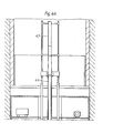
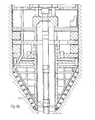
- a pilot boring tool 4.1 substantially as described above in relation to Figure 1, is rotated and advanced independently of the main boring head and is provided with one or more apertures 4.2 through which debris generated by it and by the main boring head may pass to a fluid- transport hoisting system of conventional design.
- the trailing edge of the aperture 4.2 may be provided with a blade 4.3 adapted to urge debris into the aperture.
- the sides and floor of the aperture may be horizontal or vertical or inclined or curved according to the nature of the debris to be handled, and the aperture may converge to an opening 4.4 giving access to a rotating or reciprocating fluid valving or locking arrangement of conventional design adapted to admit debris to a fluid transport duct 4.5.
- the opening 4.4 may give access to a transport duct in which the fluid pressure is less than that outside the duct, as in a vacuum conveying system, so that valving may not be necessary. Water in the bottom of the bore may be transferred to the fluid transport system in substantially the same way as described in connection with the transfer of debris.
- the duct 4.5 After entering the transport duct 4.5 the debris (or water) is entrained in the flow of transport fluid and is conveyed by it either to the surface for discharge or to some intermediate point in the bore for transfer to another hoisting system.
- the duct 4.5 is provided as required with slideably extensible or rotary couplings such as 4.6 provided to accommodate movement of the pilot boring tool 4.1 relative to the main fixed length 4.7 of the said duct. Similar accommodation may be provided for a downcoming duct 4.8 supplying transport fluid to the system.
- the assembly comprising the ducting 4.5 and 4.8 and the components of the fluid valving or locking equipment may be detached and lifted from the pilot boring tool.
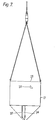
- a pilot boring tool 5.1 similar to a conventional drill is rotated and advanced independently of a main boring tool 5.2 by means of an elongate hollow tubular member or drill tube 5.3 suspended from a yoke 5.4 supported by lifting cylinders 5.5.
- the drill tube 5.3 is rotated by a power unit 5.6 via conventional sliding key means (not shown).
- the tube 5.3 is rotated by a power unit carried upon the yoke 5.4.
- the drill tube 5.3 is joined as shown at 5.7 to enable its length to be modified to suit particularly ground conditions or to facilitate its removal from the hole.
- the tube 5.3 will incorporate a second concentric tube 5.8, the annular space between tubes 5.3 and 5.8 being employed to carry fluid under pressure downwards into the hole to be used in order to generate a movement of fluid up the inner tube 5.8, the said fluid being drawn from the bore created by the pilot boring tool 5.1 past the cutters of the said tool in order to entrain and remove debris from the vicinity of the tool.
- a reverse-circulation system is commonly used in drilling and is generally referred to as a reverse-circulation system.
- the fluid filling the bore is water, sometimes mixed with mud or other materials in order to enhance its debris-carrying capacity, and the pressure fluid employed to urge it up the inner tube 5.8 may conventionally be air or water. In some cases the fluid in the pilot bore may be air.
- a tube 5.9 is attached via a swivel 5.10 to the head of the inner tube 5.8 in order to receive the ascending fluid and to direct it to a hoistable container 5.11.
- the container 5.11 may incorporate screening means adapted to retain solids while permitting liquid to escape from the container and return down the hole to the pilot bore via appropriate ducting. Alternatively the screening means may be inserted between the tube 5.9 and the container 5.11 in order to separate solids and liquid, before the former enter the container.
- the tube 5.9 may, when the container 5.11 is full, be diverted to a second container 5.12 thus leaving the first container free to be hoisted to the surface and emptied without significant interruption of the drilling process.
- main boring head 5.2 may be partially immersed in a liquid used to fill and clear the pilot bore. If air alone is used in the pilot bore then the main boring head will also obviously be immersed in it. Liquid used in the pilot bore is replenished by liquid returning from the entry to the hoisting system already described and maintained at a level in the bore chosen to optimise drill progress.
- Debris from the main boring head 5.2 falls, as already described in relation to other embodiments of the invention, towards (and in this case into) the pilot bore.
- Stabilising or reaming tools of a conventional form are attached to the drill tube 5.3 at locations 5.13 .and 5.14 in order to guide it during drilling but, in accordance with this embodiment of the invention, they are adapted by the addition of collars 5.15 to restrict the passage of debris from the main boring head until it has been reduced to a particle size compatible with the debris transporting system already described.
- the collars thus constitute the debris collecting means attached to the tubular part 5.8.
- the reduction in size is effected by grinding the debris in the tapering annulus between the rotating collars 5.15 and the static wall of the pilot bore, such grinding action being facilitated by appropriate shaping of the generally conical surfaces of the collars 5.15 and the provision of ribs or protrusions as required on the said surfaces. Obstructions may be inserted in the gap between the collars 5.15 and the walls of the pilot bore in order to regulate the downward movement of debris to a rate consistent with the capacity of the fluid transport system.
- the said regulatory means may be adjustable so that the optimum rate of flow of debris might be varied for different kinds of debris. For example, dense debris might require a lower rate of feed and might have to be reduced to a smaller size in order to avoid the risk of blockage in the tube 5.8 or in the passage leading thereto.
- pilot boring tool The whole assembly of pilot boring tool, its tubing and its driving and guiding means is removable from the pilot bore in order to permit access for the ground treatment and other purposes as described hereinbefore.
- a pilot boring tool 6.1 is rigidly attached to a main boring tool 6.2.
- the main boring tool 6.2 is substantially as heretofore described, but the pilot boring tool 6.1 is no longer in the form of a complete cylinder, being cut away over a substantial portion of its circumference and a corresponding portion of its base 6.5, so as to leave its interior exposed to a substantial portion of the cut or bored surface of the pilot hole. Its remaining base area is provided with cutting tools 6.3 sufficient in number and form to enable it to bore at the same rate as the main boring tool.
- the leading edge of the base of the pilot boring tool 6.1 is provided with a plough blade or scraping blade or toothed blade 6.4 so angled and orientated as to prevent, so far as possible, debris in the pilot bore from entering the space between the pilot boring tool base 6.5 and the base 6.6 of the pilot hole.
- the blade 6.4 thus serves to keep the pilot cutting tools 6.3 as free as possible from previously cut debris.
- Another blade 6.7 is attached to the leading edge of the rest of the pilot boring tool 6.1 in order, in similar fashion, to exclude debris from the annular gap 6.8 between the part-cylindrical surface 6.9 of the pilot boring tool 6.1 and the walls 6.10 of the pilot hole.
- blades such as blade 6.11 may be attached to the main boring tool 6.2 in order to deflect debris descending from the main boring cutters 6.12 away from the said annular gap 6.8.
- Debris from the main cutters 6.12 and the pilot cutters 6.3 accumulated in the pilot bore may be removed by mechanical grabs (not illustrated), or by fluid transport means substantially as heretofore described, or by bucket means substantially as heretofore described.
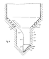
- a debris removal b cket 7.1 illustrated in Figure 7 having a shape adapted to fit closely within the pilot boring tool 6.1 and provided with one or more apertures 7.2 in its base for the purpose of admitting debris from the lower portion of the pilot bore. Debris descending from the main bore is permitted to flow into the bucket 7.1 over its top edge 7.3, the height of the bucket being chosen so as not to obstruct such flow.
- the apertures 7.2 are provided with hinged covers 7.4 so that they may be closed in order to prevent spillage when the bucket 7.1 is hoisted to discharge its debris either on the surface or at some transfer point in or above the boring machine. Closure of the hinged covers 7.4 may be effected by mechanical, electrical, or hydraulic means. When open, the covers 7.4 may serve as scrapers directing debris into the apertures 7.2 thus permitting the bucket 7.1 to work its way into an existing heap of debris as it is lowered. In this respect the bucket 7.1 may function as a temporary boring tool of a type in common use for boring holes in weak ground.
- latches which may or may not be retractable, are provided on the bucket 7.1 to engage projections or edges_or recesses in the pilot boring tool 6.1 so as to receive appropriate locational, rotational and thrusting forces from it.
- the latch 7.5 is intended to engage beneath the inclined leading edge 6.13 of the pilot boring tool 6.1 in order to receive rotational and downward thrusting forces.
- the latch 7.5 may be retracted in order to release the bucket 7.1 prior to hoisting.
Landscapes
- Engineering & Computer Science (AREA)
- Mining & Mineral Resources (AREA)
- Life Sciences & Earth Sciences (AREA)
- Geology (AREA)
- General Life Sciences & Earth Sciences (AREA)
- Geochemistry & Mineralogy (AREA)
- Physics & Mathematics (AREA)
- Environmental & Geological Engineering (AREA)
- Fluid Mechanics (AREA)
- Mechanical Engineering (AREA)
- Earth Drilling (AREA)
Applications Claiming Priority (2)
| Application Number | Priority Date | Filing Date | Title |
|---|---|---|---|
| GB8034241 | 1980-10-23 | ||
| GB8034241 | 1980-10-23 |
Publications (1)
| Publication Number | Publication Date |
|---|---|
| EP0050954A1 true EP0050954A1 (de) | 1982-05-05 |
Family
ID=10516861
Family Applications (1)
| Application Number | Title | Priority Date | Filing Date |
|---|---|---|---|
| EP81304896A Withdrawn EP0050954A1 (de) | 1980-10-23 | 1981-10-20 | Tiefbohrer |
Country Status (1)
| Country | Link |
|---|---|
| EP (1) | EP0050954A1 (de) |
Cited By (10)
| Publication number | Priority date | Publication date | Assignee | Title |
|---|---|---|---|---|
| FR2535779A1 (fr) * | 1982-11-05 | 1984-05-11 | Fabre Jean | Outil de forage du sol du type a carottier |
| FR2538847A1 (fr) * | 1982-12-30 | 1984-07-06 | Fabre Jean | Outil de forage du sol du type a carottier |
| FR2640313A1 (fr) * | 1988-12-14 | 1990-06-15 | Claudeville Xavier | Trepan de forage avec fraise a mouvement de va-et-vient en spirale |
| WO2000053882A1 (en) * | 1999-03-11 | 2000-09-14 | I.M.T. S.P.A. | Drill for making wide diameter and high depth holes and method for carrying out said holes |
| WO2014102020A3 (de) * | 2012-12-24 | 2015-03-26 | Herrenknecht Aktiengesellschaft | Vorrichtung zum abteufen eines schachts |
| EP2942473A3 (de) * | 2014-05-07 | 2016-03-16 | Tudor21 Ltd | Lochschneidvorrichtung |
| CN105649632A (zh) * | 2016-03-30 | 2016-06-08 | 中国铁建重工集团有限公司 | 竖井掘进机及其刀头组件 |
| WO2016116910A1 (en) * | 2015-01-23 | 2016-07-28 | Master Drilling South Africa (Pty) Ltd | Shaft enlargement arrangement for a boring system |
| CN111140236A (zh) * | 2020-03-31 | 2020-05-12 | 中铁工程装备集团有限公司 | 一种自带先导孔开挖功能的新型竖井钻机 |
| EP3516170A4 (de) * | 2016-09-21 | 2020-05-20 | Master Sinkers (PTY) LTD | Wellenerweiterungsanordnung für ein bohrsystem |
Citations (13)
| Publication number | Priority date | Publication date | Assignee | Title |
|---|---|---|---|---|
| DE159349C (de) * | ||||
| DE97706C (de) * | ||||
| FR337785A (fr) * | 1903-12-16 | 1904-04-25 | Res | Dispositif de sondage perfectionné |
| US1391626A (en) * | 1920-04-27 | 1921-09-20 | Richard J Bequette | Drill-head for well-driling apparatus |
| US1521596A (en) * | 1921-10-10 | 1925-01-06 | Casey Christopher | Reamer |
| US1803228A (en) * | 1929-11-22 | 1931-04-28 | Walter P Beaver | Digging device |
| GB801615A (en) * | 1956-04-27 | 1958-09-17 | Steinkohlenbergwerk Hannover H | Rotary drilling apparatus for the production of shafts |
| US3379264A (en) * | 1964-11-05 | 1968-04-23 | Dravo Corp | Earth boring machine |
| US3491843A (en) * | 1966-04-01 | 1970-01-27 | Jose Molina Rodriguez | Mechanism for widening galleries applicable to drilling machines |
| US4078622A (en) * | 1976-08-05 | 1978-03-14 | Taylor Myers Robert W | Road surface recessing device |
| FR2367723A1 (fr) * | 1976-10-12 | 1978-05-12 | Procter & Gamble | Pro |
| US4186808A (en) * | 1977-06-29 | 1980-02-05 | Cox Kenneth C | Earth boring machine with crushing rollers |
| GB2028897A (en) * | 1978-08-26 | 1980-03-12 | Paurat F | Equipment for the sinking of shafts |
-
1981
- 1981-10-20 EP EP81304896A patent/EP0050954A1/de not_active Withdrawn
Patent Citations (13)
| Publication number | Priority date | Publication date | Assignee | Title |
|---|---|---|---|---|
| DE159349C (de) * | ||||
| DE97706C (de) * | ||||
| FR337785A (fr) * | 1903-12-16 | 1904-04-25 | Res | Dispositif de sondage perfectionné |
| US1391626A (en) * | 1920-04-27 | 1921-09-20 | Richard J Bequette | Drill-head for well-driling apparatus |
| US1521596A (en) * | 1921-10-10 | 1925-01-06 | Casey Christopher | Reamer |
| US1803228A (en) * | 1929-11-22 | 1931-04-28 | Walter P Beaver | Digging device |
| GB801615A (en) * | 1956-04-27 | 1958-09-17 | Steinkohlenbergwerk Hannover H | Rotary drilling apparatus for the production of shafts |
| US3379264A (en) * | 1964-11-05 | 1968-04-23 | Dravo Corp | Earth boring machine |
| US3491843A (en) * | 1966-04-01 | 1970-01-27 | Jose Molina Rodriguez | Mechanism for widening galleries applicable to drilling machines |
| US4078622A (en) * | 1976-08-05 | 1978-03-14 | Taylor Myers Robert W | Road surface recessing device |
| FR2367723A1 (fr) * | 1976-10-12 | 1978-05-12 | Procter & Gamble | Pro |
| US4186808A (en) * | 1977-06-29 | 1980-02-05 | Cox Kenneth C | Earth boring machine with crushing rollers |
| GB2028897A (en) * | 1978-08-26 | 1980-03-12 | Paurat F | Equipment for the sinking of shafts |
Cited By (21)
| Publication number | Priority date | Publication date | Assignee | Title |
|---|---|---|---|---|
| FR2535779A1 (fr) * | 1982-11-05 | 1984-05-11 | Fabre Jean | Outil de forage du sol du type a carottier |
| FR2538847A1 (fr) * | 1982-12-30 | 1984-07-06 | Fabre Jean | Outil de forage du sol du type a carottier |
| FR2640313A1 (fr) * | 1988-12-14 | 1990-06-15 | Claudeville Xavier | Trepan de forage avec fraise a mouvement de va-et-vient en spirale |
| WO2000053882A1 (en) * | 1999-03-11 | 2000-09-14 | I.M.T. S.P.A. | Drill for making wide diameter and high depth holes and method for carrying out said holes |
| US6655474B1 (en) | 1999-03-11 | 2003-12-02 | I.M.T. S.P.A. | Drill for making wide diameter and high depth holes and method for carrying out said holes |
| WO2014102020A3 (de) * | 2012-12-24 | 2015-03-26 | Herrenknecht Aktiengesellschaft | Vorrichtung zum abteufen eines schachts |
| CN104870747A (zh) * | 2012-12-24 | 2015-08-26 | 海瑞克股份公司 | 用于掘进井的设备 |
| RU2641052C2 (ru) * | 2012-12-24 | 2018-01-15 | Херренкнехт Акциенгезельшафт | Устройство для проходки шахтного ствола |
| GB2525892B (en) * | 2014-05-07 | 2017-05-24 | Tudor21 Ltd | A hole cutting device |
| EP2942473A3 (de) * | 2014-05-07 | 2016-03-16 | Tudor21 Ltd | Lochschneidvorrichtung |
| WO2016116910A1 (en) * | 2015-01-23 | 2016-07-28 | Master Drilling South Africa (Pty) Ltd | Shaft enlargement arrangement for a boring system |
| CN107407131A (zh) * | 2015-01-23 | 2017-11-28 | 马斯特森可斯私人有限公司 | 用于钻探系统的竖井扩大布置 |
| RU2712866C2 (ru) * | 2015-01-23 | 2020-01-31 | Мастер Синкерз (Пти) Лтд | Бурильная система с установкой для расширения ствола |
| CN107407131B (zh) * | 2015-01-23 | 2020-04-14 | 马斯特森可斯私人有限公司 | 用于钻探系统的竖井扩大布置 |
| US10697246B2 (en) | 2015-01-23 | 2020-06-30 | Master Drilling South Africa (Pty) Ltd. | Shaft enlargement arrangement for a boring system |
| AU2016210554B2 (en) * | 2015-01-23 | 2021-03-25 | Master Sinkers (Pty) Ltd | Shaft enlargement arrangement for a boring system |
| CN105649632A (zh) * | 2016-03-30 | 2016-06-08 | 中国铁建重工集团有限公司 | 竖井掘进机及其刀头组件 |
| EP3516170A4 (de) * | 2016-09-21 | 2020-05-20 | Master Sinkers (PTY) LTD | Wellenerweiterungsanordnung für ein bohrsystem |
| US10947845B2 (en) | 2016-09-21 | 2021-03-16 | Master Sinkers (Pty) Ltd | Shaft enlargement arrangement for a boring system |
| AU2017332866B2 (en) * | 2016-09-21 | 2023-07-06 | Master Sinkers (Pty) Ltd | Shaft enlargement arrangement for a boring system |
| CN111140236A (zh) * | 2020-03-31 | 2020-05-12 | 中铁工程装备集团有限公司 | 一种自带先导孔开挖功能的新型竖井钻机 |
Similar Documents
| Publication | Publication Date | Title |
|---|---|---|
| CN107407131B (zh) | 用于钻探系统的竖井扩大布置 | |
| US3379264A (en) | Earth boring machine | |
| AU2003228414B2 (en) | Apparatus for sampling drill hole cuttings | |
| AU2017332866B2 (en) | Shaft enlargement arrangement for a boring system | |
| US4274675A (en) | Shaft-sinking apparatus with milling head and central worm conveyor | |
| US3185226A (en) | Shaft sinking apparatus | |
| CN116084957B (zh) | 深竖井掘进机 | |
| CN110671120B (zh) | 一种敞开式外护盾掘进装置及坍塌巷道掘进方法 | |
| JP4131493B2 (ja) | 立坑掘削装置 | |
| US5366029A (en) | Large shaft over-reamer apparatus and method | |
| JPH10159127A (ja) | 地面に深い溝を掘削する装置および方法 | |
| US4701073A (en) | Shaft sinking method | |
| US2212236A (en) | Hydraulic excavating bucket | |
| CN120007265B (zh) | 一种盲竖井掘进设备 | |
| US12553286B2 (en) | Device for sinking a vertical borehole | |
| JP3835992B2 (ja) | 圧気ケーソン施工設備 | |
| GB2116614A (en) | Method and apparatus for driving hollow piles into the ground | |
| EP0184460A2 (de) | Schachtabteufverfahren | |
| CA3160587C (en) | Device for sinking a vertical borehole | |
| CA3044325C (en) | Shaft enlargement arrangement for a boring system | |
| RU2795402C2 (ru) | Компоновка для расширения ствола шахты для буровой системы |
Legal Events
| Date | Code | Title | Description |
|---|---|---|---|
| PUAI | Public reference made under article 153(3) epc to a published international application that has entered the european phase |
Free format text: ORIGINAL CODE: 0009012 |
|
| AK | Designated contracting states |
Designated state(s): AT BE CH DE FR GB IT LU NL SE |
|
| STAA | Information on the status of an ep patent application or granted ep patent |
Free format text: STATUS: THE APPLICATION HAS BEEN WITHDRAWN |
|
| 18W | Application withdrawn |
Withdrawal date: 19820726 |
|
| RIN1 | Information on inventor provided before grant (corrected) |
Inventor name: MILLER, ROY BRUCE Inventor name: SALTER, MARTIN DE GAUDRION Inventor name: WINDER, RICHARD BRYAN |