EP0050962A1 - Courroie pour transporteur à courroie - Google Patents
Courroie pour transporteur à courroie Download PDFInfo
- Publication number
- EP0050962A1 EP0050962A1 EP81304959A EP81304959A EP0050962A1 EP 0050962 A1 EP0050962 A1 EP 0050962A1 EP 81304959 A EP81304959 A EP 81304959A EP 81304959 A EP81304959 A EP 81304959A EP 0050962 A1 EP0050962 A1 EP 0050962A1
- Authority
- EP
- European Patent Office
- Prior art keywords
- belt
- core layer
- conveyor belt
- portions
- end edge
- Prior art date
- Legal status (The legal status is an assumption and is not a legal conclusion. Google has not performed a legal analysis and makes no representation as to the accuracy of the status listed.)
- Granted
Links
- 239000012792 core layer Substances 0.000 claims abstract description 26
- 239000010410 layer Substances 0.000 claims abstract description 24
- 229920001971 elastomer Polymers 0.000 claims abstract description 21
- 239000005060 rubber Substances 0.000 claims abstract description 21
- 230000003014 reinforcing effect Effects 0.000 claims description 23
- 208000018747 cerebellar ataxia with neuropathy and bilateral vestibular areflexia syndrome Diseases 0.000 description 10
- 239000000463 material Substances 0.000 description 10
- 239000004677 Nylon Substances 0.000 description 4
- 229920001778 nylon Polymers 0.000 description 4
- 229910000831 Steel Inorganic materials 0.000 description 3
- 239000010959 steel Substances 0.000 description 3
- 229920000728 polyester Polymers 0.000 description 2
- 241000872198 Serjania polyphylla Species 0.000 description 1
- 229920002978 Vinylon Polymers 0.000 description 1
- 238000005452 bending Methods 0.000 description 1
- 239000006229 carbon black Substances 0.000 description 1
- 239000008187 granular material Substances 0.000 description 1
- 238000002156 mixing Methods 0.000 description 1
- 239000005011 phenolic resin Substances 0.000 description 1
- 229920000642 polymer Polymers 0.000 description 1
- 239000000126 substance Substances 0.000 description 1
- XLYOFNOQVPJJNP-UHFFFAOYSA-N water Substances O XLYOFNOQVPJJNP-UHFFFAOYSA-N 0.000 description 1
Images

Classifications
-
- B—PERFORMING OPERATIONS; TRANSPORTING
- B65—CONVEYING; PACKING; STORING; HANDLING THIN OR FILAMENTARY MATERIAL
- B65G—TRANSPORT OR STORAGE DEVICES, e.g. CONVEYORS FOR LOADING OR TIPPING, SHOP CONVEYOR SYSTEMS OR PNEUMATIC TUBE CONVEYORS
- B65G15/00—Conveyors having endless load-conveying surfaces, i.e. belts and like continuous members, to which tractive effort is transmitted by means other than endless driving elements of similar configuration
- B65G15/08—Conveyors having endless load-conveying surfaces, i.e. belts and like continuous members, to which tractive effort is transmitted by means other than endless driving elements of similar configuration the load-carrying surface being formed by a concave or tubular belt, e.g. a belt forming a trough
-
- B—PERFORMING OPERATIONS; TRANSPORTING
- B65—CONVEYING; PACKING; STORING; HANDLING THIN OR FILAMENTARY MATERIAL
- B65G—TRANSPORT OR STORAGE DEVICES, e.g. CONVEYORS FOR LOADING OR TIPPING, SHOP CONVEYOR SYSTEMS OR PNEUMATIC TUBE CONVEYORS
- B65G15/00—Conveyors having endless load-conveying surfaces, i.e. belts and like continuous members, to which tractive effort is transmitted by means other than endless driving elements of similar configuration
- B65G15/30—Belts or like endless load-carriers
- B65G15/32—Belts or like endless load-carriers made of rubber or plastics
- B65G15/40—Belts or like endless load-carriers made of rubber or plastics troughed or tubular; formed with joints facilitating troughing
-
- B—PERFORMING OPERATIONS; TRANSPORTING
- B65—CONVEYING; PACKING; STORING; HANDLING THIN OR FILAMENTARY MATERIAL
- B65G—TRANSPORT OR STORAGE DEVICES, e.g. CONVEYORS FOR LOADING OR TIPPING, SHOP CONVEYOR SYSTEMS OR PNEUMATIC TUBE CONVEYORS
- B65G2201/00—Indexing codes relating to handling devices, e.g. conveyors, characterised by the type of product or load being conveyed or handled
- B65G2201/04—Bulk
Definitions
- the present invention relates to a conveyor belt, and more particularly to improvements in a conveyor belt suitable for use in a belt of a so-called cylindrical belt conveyor.
- the cylindrical conveyor for transporting mainly powder-like or granular materials in which the belt of the conveyor is pinched from both sides by means of a plurality of pinching rollers so as to roll the belt into the cylindrical form in cross-section has advantages in that the materials to be transported by the conveyor belt are effectively prevented from scattering out of the conveyor belt and from getting wet by rain and water, while it can transport the materials effectively even though the transporting line is inclined.
- Such a conveyor belt is required to possess a property permitting the belt to be quickly rolled into the cylindrical form by means of the pinching rollers, while it can be restored to the original flat form by removal of the pinching force.
- the thickness of the belt and, particularly, the thickness of the core layer thereof for reinforcing the strength of the belt necessarily increase, so that it is made difficult or impossible for the belt to be rolled into the cylindrical form by the action of the pinching rollers and to restore its original flat form by the removal of the pinching action of the pinching rollers, while, as described later, the overlapping end edge portions of the belt when it is rolled into the cylindrical form in cross-section will yield to the gravitational force acting thereon so as to collapse'inwardly, thereby causing permanent deformation in the overlapping end edge portions of the belt which makes it difficult to supply the materials onto the belt after it is restored to its flat form and, in the extreme instance, the restoration of the belt to its flat form is made impossible.
- the present invention aims at avoiding the above described disadvantages of the prior art conveyor belt.
- the conveyor belt constructed in accordance with a feature of the present invention which includes an upper cover layer, a lower cover layer and a reinforcing core layer embedded between the upper and lower cover layers is characterised in that the core layer is integrally formed with thinned portions at both sides of a thickened central portion of the core layer with the stepped shoulder portions formed between the central thickened portion and the thinned side portions being located on the upper surface of the core layer thereby providing a flat surface to the entire lower surface of the core layer.
- the upper and lower cover layers are resilient - preferably rubber.
- the belt constructed as described above it is easily rolled into the cylindrical form by pinching the belt from both sides thereof by means of the pinching rollers, while the uniform surface pressure is maintained in the lower surface of the belt thereby reducing the wear and fatigue of the lower surface of the belt contacting with the guide pulleys.
- the belt may be provided with stiffened sections located widthwise of the belt in symmetry to each other with respect to the centre line of the belt and extending lengthwise thereof, which serve to prevent collapsing of the overlapped end edge portions of the belt inwardly by the gravitational force acting thereon tending to generate permanent deformation at the collapsing portions or to make it difficult to supply materi.als onto the belt after it is restored to the flattened state for the transport of the material.
- the prior art conveyor belt 1 is shown rolled into the cylindrical form in cross-section by means of the pinching rollers 2 with the end edge portions la and lb overlapping each other.
- the overlapping end edge portions la and lb will yield to the gravitational force acting thereon so that they tend to collapse inwardly.
- a disadvantage of the prior art conveyor belt is that the overlapping end edge portions la and lb are subjected to permanent deformation, so that it is made difficult to safely supply the materials onto the belt after it is restored to its flat form for the transport of the materials or it is made impossible to restore the belt to its flat form.
- the belt 3 comprises an upper cover rubber layer 4, a lower cover rubber layer 5, a reinforcing core layer 6 embedded between the upper and lower cover rubber layers 4 and 5 and made of materials such as nylon canvas and steel cords and the like, and a pair of elongation-resisting reinforcing layers 7 embedded in the upper cover rubber layer 4 and abutting against or secured to the upper surfaces of the outer ends of the respective end edge portions 6a of the core layer 6.
- the reinforcing core layer 6 is made of materials such as laminated nylon or polyester canvas or nylon or steel cords having a high tensile strength and a high modulus of elasticity.
- the end edge portions 6a of the core layer 6 are made thinner than the central portion 6b in order to reduce resistance against bending widthwise -of the belt 3, with the respective stepped shoulder portions between the thickened central portion 6b and the thinned side portions 6a being located on the upper side of the core layer 6 so as to maintain the lower surface thereof in the flat form thereby permitting the surface pressure generated by the guide pulleys supporting the belt 3 between the same and the pulleys to be kept uniform so that local fatigue or wear generated in the lower cover rubber layer 5 is kept to the minimum.
- the elongation-resisting reinforcing layers 7 serve to maintain the elongation'lengthwise of the respective end edge portions of the belt 3 to the minimum, thereby urging positively the outer overlapping end edge portion of the belt operated in the cylindrically rolled state against the inner overlapping end edge portion of the belt as described later in connection with Fig.5, so that the outer overlapping end edge portion of the belt 3 is prevented from moving or stripping apart from the inner overlapping end edge portion of the belt 3, because the elongation lengthwise of the outer end edge portion of the belt 3 is limited to the minimum by virtue of the provision of the elongation-resisting reinforcing layers 7 even in the position intermediate the neighbouring pinching rollers located in spaced relationship lengthwise of the belt 3, i.e. in positions spaced a substantial distance between the pinching rollers arranged in the longitudinal direction of the belt 3, while the cross-sectional configuration of the belt 3 is kept exactly in the cylindrical form with the overlapping end edge portions thereof held in contact with each other.
- the belt 8 comprises in the similar manner as that shown in Fig.2 an upper cover rubber layer 9, a lower cover rubber layer 10, a reinforcing core layer 11 embedded between the upper and lower cover rubber layers 9 and 10, and two pairs of reinforcing canvases 12a and 12b, each pair being embedded in the upper and lower cover rubber layers 9 and 10 at the upper side and the lower side of the core layer 11, respectively, at positions in accordance with the present invention as described hereinbelow.
- the reinforcing canvases 12a and 12b are preferably made of materials such as nylon, vinylon or polyester canvas or cords or steel cords and the like.
- the positions where the respective pairs of the reinforcing canvases 12a and 12b are embedded in the belt 8 are so determined that the positions of the reinforcing canvases 12a and 12b are symmetrical to each other with respect to the centre line of the conveyor belt 8 and the centre of each of the reinforcing canvases 12a and 12b is preferably set to the position spaced from the respective end edges of the belt 8 by about b, where b.is the width of the belt 8, while the width of each of the reinforcing canvases 12a and 12b is preferably in the range of b and b.
- the reinforcing canvases 12a and 12b are positioned in the side wall portions of the cylindrically rolled belt 8 extending lengthwise thereof with the overlapping end edge portions of the belt 8 extending upwardly and inwardly toward each other so as to form the cylindrical form.
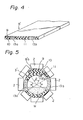
- Fig.4 shows a further embodiment of the conveyor belt of the present invention.
- the belt 8' is provided with a pair of high hardness rubbers 13a and 13b each having a width generally equal to that of the reinforcing canvases 12a, 12b and embedded in the belt 8' in place of the reinforcing canvases 12a and 12b shown in Fig.3 at positions corresponding to those where the reinforcing canvases 12a, 12b are located.
- the high hardness rubbers 13a and 13b have a Shore hardness of 75 or higher, and they can be prepared by adding suitable amount of phenol resin to the mass of rubber, or by blending 80 parts or more of carbon black with 100 parts of rubber, or by adding polymers such as high stylene and other like substance to the mass of rubber.
- Fig.5 shows the conditions under which the belt 8' shown in Fig.4 is operated in the cylindrical form in cross-section by using a plurality of pinching rollers 2 arranged around the periphery of the belt 8'.
- the high hardness rubbers 13a and 13b are located in the side wall portions of the belt 8' as shown and the centre angle ⁇ subtended by the high hardness rubbers 13a, 13b is about 60 - 90°.
- the centre angle ⁇ subtended by the overlapping end edge portions 8'a and 8'b is about 50°.
- the restoring force for restoring the overlapping end edge portions 8'a and 8'b to their original flat form is given by the high hardness rubbers 13a, 13b so that the overlapping end edge portions 13a and 13b of'the belt 8' are positively prevented from collapsing inwardly by the action of the gravitational force acting thereon or from being subjected to permanent deformation thereby making it possible to maintain exact cylindrical form in cross-section of the belt 8' and safe transport of the materials M held in the cylindrical form of the belt 8'.
- the conveyor belt constructed in accordance with the present invention can be easily rolled into the cylindrical form in cross-section by using the pinching rollers by virtue of the fact that the central portion of the reinforcing layer is made thicker in comparison with both side portions integral thereto. Further, since the lower surface of the core layer is made flat without any stepped shoulder portions, the uniform surface pressure is maintained over the lower surface of the belt contacting with the guide pulleys thereby reducing local fatigue and wear in'the lower surface of the belt.
- the elongation of the end edges of the belt is positively limited to the minimum so that the exact cylindrical form in cross-section of the belt is maintained without causing stripping of the outer overlapping end edge portion of the belt from the inner overlapping end edge portion even at positions spaced apart from the position at which the belt is pinched by the pinching rollers, i.e. even at positions where the belt is not pinched by the pinching rollers.
- the conveyor belt of the present invention which is provided with locally stiffened portions extending lengthwise of.the belt, the collapsing of the belt rolled into the cylindrical form in cross-section is positively prevented, while permanent deformation at the collapsing portions of the belt is positively prevented from occurring.
Landscapes
- Engineering & Computer Science (AREA)
- Mechanical Engineering (AREA)
- Structure Of Belt Conveyors (AREA)
- Belt Conveyors (AREA)
Applications Claiming Priority (2)
| Application Number | Priority Date | Filing Date | Title |
|---|---|---|---|
| JP14753280A JPS5772506A (en) | 1980-10-23 | 1980-10-23 | Conveyer belt |
| JP147532/80 | 1980-10-23 |
Publications (2)
| Publication Number | Publication Date |
|---|---|
| EP0050962A1 true EP0050962A1 (fr) | 1982-05-05 |
| EP0050962B1 EP0050962B1 (fr) | 1984-12-27 |
Family
ID=15432433
Family Applications (1)
| Application Number | Title | Priority Date | Filing Date |
|---|---|---|---|
| EP81304959A Expired EP0050962B1 (fr) | 1980-10-23 | 1981-10-22 | Courroie pour transporteur à courroie |
Country Status (5)
| Country | Link |
|---|---|
| EP (1) | EP0050962B1 (fr) |
| JP (1) | JPS5772506A (fr) |
| AU (1) | AU544489B2 (fr) |
| CA (1) | CA1166990A (fr) |
| DE (1) | DE3167975D1 (fr) |
Cited By (16)
| Publication number | Priority date | Publication date | Assignee | Title |
|---|---|---|---|---|
| FR2557546A1 (fr) * | 1983-12-29 | 1985-07-05 | Tokai Rubber Ind Ltd | Courroie cylindrique de convoyage |
| US4572359A (en) * | 1983-04-11 | 1986-02-25 | Bridgestone Tire Company Limited | Conveyor belt |
| US4625860A (en) * | 1985-02-27 | 1986-12-02 | Sumitomo Heavy Industries, Ltd | Tubular belt conveyor |
| EP0253148A1 (fr) * | 1986-07-17 | 1988-01-20 | Continental Aktiengesellschaft | Dispositif de transport à bande tubulaire |
| GB2195309A (en) * | 1986-09-30 | 1988-04-07 | Okazaki Haruo | A belt for a tubular belt conveyor |
| WO1988009759A1 (fr) * | 1987-06-12 | 1988-12-15 | O&K Orenstein & Koppel Aktiengesellschaft | Bande transporteuse |
| EP0315820A1 (fr) * | 1987-11-11 | 1989-05-17 | O & K Orenstein & Koppel Aktiengesellschaft | Procédé et chariot entraîneur pour le guidage de bandes transporteuses enroulées en forme de tuyau flexible |
| US5060787A (en) * | 1987-12-18 | 1991-10-29 | Lennart Tingskog | Belt conveyor and conveyor belt therefor |
| DE4024359A1 (de) * | 1990-08-01 | 1992-02-06 | Continental Ag | Foerdergurt fuer schlauchband-foerderanlagen |
| DE4212824C1 (fr) * | 1992-04-16 | 1993-08-12 | Conrad Scholtz Gmbh, 2000 Hamburg, De | |
| US5351810A (en) * | 1990-12-28 | 1994-10-04 | Conveytech Systems Ab | Conveyor belt |
| JP2011079675A (ja) * | 2009-10-09 | 2011-04-21 | Veyance Technologies Inc | 様々な可撓性を有するコンベアベルトおよびそれを組み立てる方法 |
| WO2013024050A1 (fr) * | 2011-08-12 | 2013-02-21 | ThyssenKrupp Fördertechnik GmbH | Système de courroie de convoyeur |
| WO2015066063A1 (fr) * | 2013-10-28 | 2015-05-07 | Brinager Cecil | Système et procédé de transport de matériaux en continu |
| CN113200290A (zh) * | 2021-04-29 | 2021-08-03 | 南京曼润高分子科技研究院有限公司 | 一种具有可变柔度的输送带和构造该输送带的方法 |
| US12173144B2 (en) * | 2017-01-13 | 2024-12-24 | Hangzhou Xinglu Technologies Co., Ltd | Rubber composition, and conveyor belt using the same |
Families Citing this family (1)
| Publication number | Priority date | Publication date | Assignee | Title |
|---|---|---|---|---|
| JPS63218416A (ja) * | 1987-03-02 | 1988-09-12 | Yoshino Rubber Kogyo Kk | ホ−ス型コンベアベルト |
Citations (2)
| Publication number | Priority date | Publication date | Assignee | Title |
|---|---|---|---|---|
| US707355A (en) * | 1901-12-07 | 1902-08-19 | John J Ridgway | Conveying-belt. |
| GB1228226A (fr) * | 1968-11-16 | 1971-04-15 |
-
1980
- 1980-10-23 JP JP14753280A patent/JPS5772506A/ja active Pending
-
1981
- 1981-10-20 CA CA000388370A patent/CA1166990A/fr not_active Expired
- 1981-10-21 AU AU76700/81A patent/AU544489B2/en not_active Ceased
- 1981-10-22 EP EP81304959A patent/EP0050962B1/fr not_active Expired
- 1981-10-22 DE DE8181304959T patent/DE3167975D1/de not_active Expired
Patent Citations (2)
| Publication number | Priority date | Publication date | Assignee | Title |
|---|---|---|---|---|
| US707355A (en) * | 1901-12-07 | 1902-08-19 | John J Ridgway | Conveying-belt. |
| GB1228226A (fr) * | 1968-11-16 | 1971-04-15 |
Cited By (29)
| Publication number | Priority date | Publication date | Assignee | Title |
|---|---|---|---|---|
| US4572359A (en) * | 1983-04-11 | 1986-02-25 | Bridgestone Tire Company Limited | Conveyor belt |
| DE3447248A1 (de) * | 1983-12-29 | 1985-07-11 | Tokai Rubber Industries Ltd., Komaki, Aichi | Endloses foerderband |
| FR2557546A1 (fr) * | 1983-12-29 | 1985-07-05 | Tokai Rubber Ind Ltd | Courroie cylindrique de convoyage |
| US4625860A (en) * | 1985-02-27 | 1986-12-02 | Sumitomo Heavy Industries, Ltd | Tubular belt conveyor |
| US4809845A (en) * | 1986-07-17 | 1989-03-07 | Continental Aktiengesellschaft | Hose belt conveyer system |
| EP0253148A1 (fr) * | 1986-07-17 | 1988-01-20 | Continental Aktiengesellschaft | Dispositif de transport à bande tubulaire |
| GB2195309A (en) * | 1986-09-30 | 1988-04-07 | Okazaki Haruo | A belt for a tubular belt conveyor |
| WO1988009759A1 (fr) * | 1987-06-12 | 1988-12-15 | O&K Orenstein & Koppel Aktiengesellschaft | Bande transporteuse |
| US5080221A (en) * | 1987-06-12 | 1992-01-14 | O & K Orenstein & Koppel Aktiengesellschaft | Roller belt |
| EP0315820A1 (fr) * | 1987-11-11 | 1989-05-17 | O & K Orenstein & Koppel Aktiengesellschaft | Procédé et chariot entraîneur pour le guidage de bandes transporteuses enroulées en forme de tuyau flexible |
| US5060787A (en) * | 1987-12-18 | 1991-10-29 | Lennart Tingskog | Belt conveyor and conveyor belt therefor |
| DE4024359A1 (de) * | 1990-08-01 | 1992-02-06 | Continental Ag | Foerdergurt fuer schlauchband-foerderanlagen |
| WO1992002439A1 (fr) * | 1990-08-01 | 1992-02-20 | Continental Aktiengesellschaft | Bande transporteuse pour convoyeur a bande formant gaine |
| US5232084A (en) * | 1990-08-01 | 1993-08-03 | Continental Aktiengesellschaft | Conveyor belt for a tubular conveying device |
| US5351810A (en) * | 1990-12-28 | 1994-10-04 | Conveytech Systems Ab | Conveyor belt |
| DE4212824C1 (fr) * | 1992-04-16 | 1993-08-12 | Conrad Scholtz Gmbh, 2000 Hamburg, De | |
| US5328023A (en) * | 1992-04-16 | 1994-07-12 | Conrad Scholtz Gmbh | Conveyor belt for pipe conveyor |
| AU2010224388B2 (en) * | 2009-10-09 | 2015-02-12 | Contitech Usa, Inc. | Conveyor belt with varying flexibility and method of construction of same |
| CN102040074A (zh) * | 2009-10-09 | 2011-05-04 | 维扬斯科技公司 | 具有可变柔度的输送带和构造该输送带的方法 |
| EP2308779A3 (fr) * | 2009-10-09 | 2011-12-14 | Veyance Technologies, Inc. | Courroie de transport à flexibilité variable et son procédé de construction |
| US8240463B2 (en) | 2009-10-09 | 2012-08-14 | Veyance Technologies, Inc. | Conveyor belt with varying flexibility and method of construction of same |
| JP2011079675A (ja) * | 2009-10-09 | 2011-04-21 | Veyance Technologies Inc | 様々な可撓性を有するコンベアベルトおよびそれを組み立てる方法 |
| CN102040074B (zh) * | 2009-10-09 | 2015-06-03 | 维扬斯科技公司 | 具有可变柔度的输送带和构造该输送带的方法 |
| WO2013024050A1 (fr) * | 2011-08-12 | 2013-02-21 | ThyssenKrupp Fördertechnik GmbH | Système de courroie de convoyeur |
| US9010526B2 (en) | 2011-08-12 | 2015-04-21 | Thyssenkrupp Resource Technologies Gmbh | Conveyor belt system |
| WO2015066063A1 (fr) * | 2013-10-28 | 2015-05-07 | Brinager Cecil | Système et procédé de transport de matériaux en continu |
| US12173144B2 (en) * | 2017-01-13 | 2024-12-24 | Hangzhou Xinglu Technologies Co., Ltd | Rubber composition, and conveyor belt using the same |
| CN113200290A (zh) * | 2021-04-29 | 2021-08-03 | 南京曼润高分子科技研究院有限公司 | 一种具有可变柔度的输送带和构造该输送带的方法 |
| CN113200290B (zh) * | 2021-04-29 | 2022-10-25 | 南京曼润高分子科技研究院有限公司 | 一种具有可变柔度的输送带和构造该输送带的方法 |
Also Published As
| Publication number | Publication date |
|---|---|
| EP0050962B1 (fr) | 1984-12-27 |
| AU544489B2 (en) | 1985-05-30 |
| CA1166990A (fr) | 1984-05-08 |
| JPS5772506A (en) | 1982-05-06 |
| DE3167975D1 (en) | 1985-02-07 |
| AU7670081A (en) | 1982-04-29 |
Similar Documents
| Publication | Publication Date | Title |
|---|---|---|
| EP0050962A1 (fr) | Courroie pour transporteur à courroie | |
| US3880274A (en) | Cover belt conveyor | |
| US4410082A (en) | Stretchable load-retaining conveyor belt | |
| US5004098A (en) | Conveyor belt | |
| GB1588983A (en) | Conveyor for bulk materials | |
| AU5063585A (en) | Conveyor belt for bulk material handling | |
| US3666085A (en) | Mechanical belting | |
| GB2204846A (en) | Escalator hand-rail made of synthetic elastic material | |
| US6168397B1 (en) | Flexible tube of squeeze pump | |
| GB2152000A (en) | Cylindrical conveyor belt | |
| US5141101A (en) | Conveyor belt construction | |
| US6216852B1 (en) | Conveyor belt with heavier lower reinforcing layer | |
| US3545598A (en) | Laterally flexible belt conveyor | |
| US6161684A (en) | Herringbone conveyor belt | |
| AU2001264268B2 (en) | Reinforcing band for conveyer belts, and conveyer belt using the same | |
| US7060341B2 (en) | Stretchable conveyer belt and method of producing same | |
| US4449627A (en) | Anti-backbend belts | |
| EP0047739A1 (fr) | Bande transporteuse pour materiaux. | |
| US2121650A (en) | Conveyer belt | |
| WO1990003930A1 (fr) | Ameliorations apportees a des bandes transporteuses | |
| AU2013205918B2 (en) | Belt for conveyor system | |
| JP3110126B2 (ja) | 紙葉類搬送用無端ベルト | |
| US4267921A (en) | Anti-backbend belts | |
| US821121A (en) | Conveyer-belt. | |
| CA1161385A (fr) | Transporteur a courroie elastique, et structure de ladite courroie |
Legal Events
| Date | Code | Title | Description |
|---|---|---|---|
| PUAI | Public reference made under article 153(3) epc to a published international application that has entered the european phase |
Free format text: ORIGINAL CODE: 0009012 |
|
| AK | Designated contracting states |
Designated state(s): DE FR GB IT |
|
| 17P | Request for examination filed |
Effective date: 19821102 |
|
| ITF | It: translation for a ep patent filed | ||
| GRAA | (expected) grant |
Free format text: ORIGINAL CODE: 0009210 |
|
| AK | Designated contracting states |
Designated state(s): DE FR GB IT |
|
| REF | Corresponds to: |
Ref document number: 3167975 Country of ref document: DE Date of ref document: 19850207 |
|
| ET | Fr: translation filed | ||
| PLBE | No opposition filed within time limit |
Free format text: ORIGINAL CODE: 0009261 |
|
| STAA | Information on the status of an ep patent application or granted ep patent |
Free format text: STATUS: NO OPPOSITION FILED WITHIN TIME LIMIT |
|
| 26N | No opposition filed | ||
| ITTA | It: last paid annual fee | ||
| PGFP | Annual fee paid to national office [announced via postgrant information from national office to epo] |
Ref country code: FR Payment date: 19991011 Year of fee payment: 19 |
|
| PGFP | Annual fee paid to national office [announced via postgrant information from national office to epo] |
Ref country code: GB Payment date: 19991020 Year of fee payment: 19 |
|
| PGFP | Annual fee paid to national office [announced via postgrant information from national office to epo] |
Ref country code: DE Payment date: 19991022 Year of fee payment: 19 |
|
| PG25 | Lapsed in a contracting state [announced via postgrant information from national office to epo] |
Ref country code: GB Free format text: LAPSE BECAUSE OF NON-PAYMENT OF DUE FEES Effective date: 20001022 |
|
| GBPC | Gb: european patent ceased through non-payment of renewal fee |
Effective date: 20001022 |
|
| PG25 | Lapsed in a contracting state [announced via postgrant information from national office to epo] |
Ref country code: FR Free format text: LAPSE BECAUSE OF NON-PAYMENT OF DUE FEES Effective date: 20010629 |
|
| PG25 | Lapsed in a contracting state [announced via postgrant information from national office to epo] |
Ref country code: DE Free format text: LAPSE BECAUSE OF NON-PAYMENT OF DUE FEES Effective date: 20010703 |
|
| REG | Reference to a national code |
Ref country code: FR Ref legal event code: ST |