EP0051208B1 - Unité de vitrages multiples isolante - Google Patents
Unité de vitrages multiples isolante Download PDFInfo
- Publication number
- EP0051208B1 EP0051208B1 EP81108582A EP81108582A EP0051208B1 EP 0051208 B1 EP0051208 B1 EP 0051208B1 EP 81108582 A EP81108582 A EP 81108582A EP 81108582 A EP81108582 A EP 81108582A EP 0051208 B1 EP0051208 B1 EP 0051208B1
- Authority
- EP
- European Patent Office
- Prior art keywords
- insulation
- glazing unit
- multiple glazing
- contact surfaces
- spacer frame
- Prior art date
- Legal status (The legal status is an assumption and is not a legal conclusion. Google has not performed a legal analysis and makes no representation as to the accuracy of the status listed.)
- Expired
Links
- 238000009413 insulation Methods 0.000 title claims abstract 14
- 239000011521 glass Substances 0.000 claims abstract description 34
- 125000006850 spacer group Chemical group 0.000 claims abstract description 33
- 229920001971 elastomer Polymers 0.000 claims abstract description 9
- 239000000806 elastomer Substances 0.000 claims abstract description 9
- 238000009792 diffusion process Methods 0.000 claims abstract description 4
- 230000004888 barrier function Effects 0.000 claims abstract description 3
- 229920003023 plastic Polymers 0.000 claims description 3
- 239000004033 plastic Substances 0.000 claims description 3
- 239000002184 metal Substances 0.000 claims description 2
- 238000006073 displacement reaction Methods 0.000 claims 1
- 238000007789 sealing Methods 0.000 description 9
- 239000002274 desiccant Substances 0.000 description 6
- 229940125773 compound 10 Drugs 0.000 description 4
- ZLVXBBHTMQJRSX-VMGNSXQWSA-N jdtic Chemical compound C1([C@]2(C)CCN(C[C@@H]2C)C[C@H](C(C)C)NC(=O)[C@@H]2NCC3=CC(O)=CC=C3C2)=CC=CC(O)=C1 ZLVXBBHTMQJRSX-VMGNSXQWSA-N 0.000 description 4
- 239000000523 sample Substances 0.000 description 4
- 150000001875 compounds Chemical class 0.000 description 2
- 239000000945 filler Substances 0.000 description 2
- 238000009434 installation Methods 0.000 description 2
- 125000000484 butyl group Chemical group [H]C([*])([H])C([H])([H])C([H])([H])C([H])([H])[H] 0.000 description 1
- 238000004140 cleaning Methods 0.000 description 1
- 238000010276 construction Methods 0.000 description 1
- 238000011161 development Methods 0.000 description 1
- 230000018109 developmental process Effects 0.000 description 1
- 239000000428 dust Substances 0.000 description 1
- 238000005429 filling process Methods 0.000 description 1
- 239000002245 particle Substances 0.000 description 1
- 239000003566 sealing material Substances 0.000 description 1
- XLYOFNOQVPJJNP-UHFFFAOYSA-N water Chemical compound O XLYOFNOQVPJJNP-UHFFFAOYSA-N 0.000 description 1
- 230000003313 weakening effect Effects 0.000 description 1
Images

Classifications
-
- E—FIXED CONSTRUCTIONS
- E06—DOORS, WINDOWS, SHUTTERS, OR ROLLER BLINDS IN GENERAL; LADDERS
- E06B—FIXED OR MOVABLE CLOSURES FOR OPENINGS IN BUILDINGS, VEHICLES, FENCES OR LIKE ENCLOSURES IN GENERAL, e.g. DOORS, WINDOWS, BLINDS, GATES
- E06B3/00—Window sashes, door leaves, or like elements for closing wall or like openings; Layout of fixed or moving closures, e.g. windows in wall or like openings; Features of rigidly-mounted outer frames relating to the mounting of wing frames
- E06B3/66—Units comprising two or more parallel glass or like panes permanently secured together
- E06B3/663—Elements for spacing panes
- E06B3/667—Connectors therefor
Definitions
- the invention relates to a multi-pane insulating glass unit, consisting of at least two parallel glass panes and spacer frames arranged between the edge zones of their mutually facing surfaces, each of which is formed from profile tubes and from angle pieces, which protrude into the cavities of the profile tubes with pins and which corner body with two contain lateral contact surfaces parallel to each other and to the glass panes, which lie essentially in the same planes with the lateral contact surfaces of the profile tubes parallel to the glass panes, and from elastomer strips arranged between the contact surfaces of the spacer frames and the edge zones, forming a vapor diffusion barrier, at least two closable Gas filling or gas outlet bores are guided through the elbows of each spacer frame from the outside to the space between the panes delimited by the spacer frame and the glass panes, and wherein at least one profiler is in the cavity ear of each spacer frame contains a desiccant on at least part of its length, which is connected via openings to this space between the panes
- the two, protruding into the cavities of the profile tubes of the spacer frame of the angle pieces are formed directly on the corner body, such that the one Directly adjoin the elbow connected profile tubes.
- the gas filler holes or gas outlet bores which are used to introduce dry air or a light or heavy gas into the space between the spacer frame and the space between the panes, cross the corner body at an angle to the pegs, so that the axes of these bores run approximately in the diagonals of the glass panes.
- the same arrangement of the gas filling or gas outlet bores is shown by multi-pane insulating glass units with an angle piece of approximately the same cross section (US Pat. No. 3,280,523).
- the spacer frame is weakened at a particularly critical point with regard to its strength by the gas filling or gas outlet bores, or that the diameter of these bores must be kept small due to strength considerations, which in turn means only low-strength probes in the frame and limited space between the panes of glass can be inserted, so that gas exchange can take place only slowly.
- the best cleaning of the glass panes before assembly with the spacer frame there may still be dust particles on the inside of the glass panes, on which the probe leaves traces when they are inserted, which, due to their extension diagonally to the insulating glass unit, are particularly evident to the eye.
- the mouths of the gas filler or gas outlet bores are precisely at points which are particularly at risk with regard to water vapor diffusion and which are intended to obtain the greatest possible coverage with a further sealing compound.
- the profile tubes also contain a drying agent which is connected to the space between the panes through openings, the dimensions of which are selected such that the drying agent cannot get into the space between the panes. If gas filling or gas outlet bores are now provided in the profile tubes, additional precautions, for example plugs inserted into the profile tubes, must be taken to prevent the desiccant from getting into the space between the panes.
- the object of the present invention is to provide a multi-pane insulating glass unit which, with little effort, enables a rapid gas exchange of the space between the panes without clear traces on the glass panes and ensures the best seal.
- each spacer frame has at least one angle piece which contains a leg piece between the corner body and at least one of its two pins, at least its lateral contact surfaces each with the lateral contact surfaces of the corner body and the profile tubes lie essentially in common planes and that the gas filling or gas outlet bores extend through these leg pieces, the axes of which extend essentially parallel to the lateral contact faces and at right angles to the leg piece.
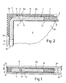
- the first embodiment of the invention illustrated in FIGS. 1-5 essentially consists of a spacer frame, designated in its entirety by 1, which is arranged sealingly between the edge zones 3a, 3b of two glass panes 4a, 4b via elastomer strips 2a, 2b.
- the elastomer strips consist of an elastic-plastic sealing material, preferably a butyl sealing compound.
- the spacer frame 1 in turn consists of four profile tubes 5, which are connected by angle pieces designated 6 in their entirety. At least one of the profile tubes 5 is at least partially filled with a drying agent 7, which is connected via a plurality of openings 8 with a smaller cross-section than the grain size of the drying agent to the pane space 9, which is separated from the glass panes 4a, 4b, the spacer frame 1 and the Elastomer strip 2a, 2b is limited.
- the depression formed by the regions of the edge zones 3a, 3b of the glass panes 4a, 4b projecting above the spacer frame 1 is completely filled with an additional sealing compound 10.
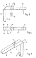
- the spacer frame 1 contains at least two angle pieces 6 of the type illustrated in greater detail in FIGS. 3-5.
- Each of these angle pieces 6 is made in one piece from plastic or metal and has a corner body 11, from which on the one hand a pin 12a and on the other hand a leg piece 13 extends at right angles thereto, which in turn continues into a pin 12b.
- the pins 12a, 12b are adapted to the cavities 5c of the profiled tubes 5 and held there in a force-fitting manner, with transverse holding ribs 14 ensuring a uniform contact force.
- the outer boundary of the corner body 11 forms an inclined surface 11 b, which extends perpendicular to the glass panes 4a, 4b and at an angle of 45 ° to the longitudinal axes of the pins 12a, 12b and creates more space for the additional sealing compound 10.
- the outer cross-sectional shape of the leg piece 13 corresponds to that of the profile tube 5 assigned to it.
- the contact surfaces 11a of the corner body 11 facing the glass panes 3a, 3b and bearing the elastomer strips 2a, 2b lie in the same planes with the corresponding contact surfaces 13a of the leg piece 13 and the contact surfaces of the profiled tube 5 pushed onto the pins 12a, 12b.
- a gas filling or gas outlet bore 15 extends through the leg piece 13, the axis 15a of which extends parallel to the longitudinal axis of the pin 12a. Through this bore 15, a gas can be introduced into the disc space 9 or be discharged from it directly or through a probe (not shown).
- a closure plug 16, which is separately illustrated in FIG. 3, is provided for closure and engages over the outer circumference of the bore 15 with its cap-like edge. A further sealing of the bore takes place with the additional sealing compound 10.
- the second embodiment of the invention differs from the first only by a different design of the angle piece, designated in its entirety by 6 ', which is described below only to the extent that there are deviations from the first embodiment.
- the pins 12'a and 12'b are provided with closely spaced holding ribs 14 and, starting from their free ends, are divided by slots 17 into a stronger tab 17a and a weaker tab 17b, so that the resilient pressure in the cavity 5c of the profile tubes 5 is improved.
- 6 each shows a pin 12'a in the delivery state and a pin 12'b in the installed state.
- a first section of the pins adjoining the tabs 17a, 17b is adapted to the cross-sectional shape of the cavity 5c of the profiled tubes 5.
- the corner body 11 ' has a rounded portion 11'b on the outside.
- two or more gas filling or gas outlet bores 15 can be provided in the same leg piece 13 or 13 ', the bore axes of which run parallel to one another and to the pin 12a or 12'a and in one common plane lying parallel to the glass pane 3b.
- An angle piece designed in this way is then sufficient for the construction of the spacer frame, while the remaining angle pieces can be constructed in a manner known per se without gas filling or gas outlet bores.
Landscapes
- Engineering & Computer Science (AREA)
- Civil Engineering (AREA)
- Structural Engineering (AREA)
- Securing Of Glass Panes Or The Like (AREA)
Claims (12)
Priority Applications (1)
| Application Number | Priority Date | Filing Date | Title |
|---|---|---|---|
| AT81108582T ATE8069T1 (de) | 1980-10-23 | 1981-10-20 | Mehrscheiben-isolierglaseinheit. |
Applications Claiming Priority (2)
| Application Number | Priority Date | Filing Date | Title |
|---|---|---|---|
| DE3040038 | 1980-10-23 | ||
| DE3040038A DE3040038C2 (de) | 1980-10-23 | 1980-10-23 | Mehrscheiben-Isolierglaseinheit mit in den Eckwinkeln des Distanzrahmens befindlichen Gaseinfüllbohrungen |
Publications (2)
| Publication Number | Publication Date |
|---|---|
| EP0051208A1 EP0051208A1 (fr) | 1982-05-12 |
| EP0051208B1 true EP0051208B1 (fr) | 1984-06-20 |
Family
ID=6115043
Family Applications (1)
| Application Number | Title | Priority Date | Filing Date |
|---|---|---|---|
| EP81108582A Expired EP0051208B1 (fr) | 1980-10-23 | 1981-10-20 | Unité de vitrages multiples isolante |
Country Status (3)
| Country | Link |
|---|---|
| EP (1) | EP0051208B1 (fr) |
| AT (1) | ATE8069T1 (fr) |
| DE (1) | DE3040038C2 (fr) |
Families Citing this family (11)
| Publication number | Priority date | Publication date | Assignee | Title |
|---|---|---|---|---|
| GB2139685A (en) * | 1983-05-13 | 1984-11-14 | Glaverbel | Corner spacer member for hollow glazing units |
| DE3324646A1 (de) * | 1983-07-08 | 1985-01-17 | Kronenberg, Hans Joachim, 5650 Solingen | Eckverbindung fuer abstandshalterrahmen von isolierglasscheiben |
| AT386455B (de) * | 1983-10-28 | 1988-08-25 | Flachglas Ag | Eckwinkel aus kunststoff zum verbinden von hohlprofilabschnitten fuer isolierglaseinheiten |
| GB2150182A (en) * | 1983-11-22 | 1985-06-26 | Patrick William Pinnington | A corner joint for frames |
| DE3628275A1 (de) | 1986-08-20 | 1988-02-25 | Erbsloeh Julius & August | Abstandhalterrahmen fuer mehrscheibenisolierglas |
| DE8707395U1 (de) * | 1987-05-22 | 1987-11-12 | Bischof, Hubert, 8033 Krailling | Isolierglasscheibe |
| DE8707918U1 (de) * | 1987-06-04 | 1987-07-23 | Isolar-Glas-Beratung GmbH, 6544 Kirchberg | Abstandshalter für Isolierglasscheiben |
| DE3822117A1 (de) * | 1988-06-30 | 1990-01-04 | Arup Alu Rohr Und Profil Gmbh | Eckverbinder fuer abstandshalterprofile von mehrscheiben-isolierglas |
| DE4024143A1 (de) * | 1990-07-30 | 1992-02-06 | Koester Helmut | Beheiztes oder gekuehltes isolierglas |
| DE9110972U1 (de) * | 1991-09-04 | 1991-11-14 | Cera Handelsgesellschaft Mbh, 8954 Biessenhofen | Geradverbinder aus Kunststoff zur Verbindung von hohlen Abstandsprofilen und hohlen Sprossenprofilen eines Mehrscheibenisolierglases |
| FR2690946A1 (fr) * | 1992-05-07 | 1993-11-12 | Saint Gobain Vitrage Int | Valve pour vitrage isolant anti-feu. |
Family Cites Families (5)
| Publication number | Priority date | Publication date | Assignee | Title |
|---|---|---|---|---|
| DE7409051U (de) * | 1974-07-04 | Kloeckner Werke Ag | Eckverbindung von Kunststoffhohlprofilen | |
| DE2410303C3 (de) * | 1974-03-05 | 1979-02-08 | Flachglas Ag Delog-Detag, 8510 Fuerth | Eckwinkel zum Verbinden von Hohlprofilrahmenabschnitten |
| DE2462494A1 (de) * | 1974-03-05 | 1977-07-07 | Delog Detag Flachglas Ag | Eckwinkel zum verbinden von hohlprofilrahmenabschnitten fuer isolierglas |
| DE7933613U1 (de) * | 1979-11-29 | 1980-04-24 | Wilh. Frank Gmbh, 7022 Leinfelden- Echterdingen | Von einem rahmen aus kunststoff- profilstaeben umgebene isolierglaseinheit |
| DE8028304U1 (de) * | 1980-10-23 | 1981-02-26 | Ggn Glashandels-Gesellschaft Noerdlingen Mbh & Co Kg, 8860 Noerdlingen | Mehrscheiben-isolierglaseinheit |
-
1980
- 1980-10-23 DE DE3040038A patent/DE3040038C2/de not_active Expired
-
1981
- 1981-10-20 EP EP81108582A patent/EP0051208B1/fr not_active Expired
- 1981-10-20 AT AT81108582T patent/ATE8069T1/de not_active IP Right Cessation
Also Published As
| Publication number | Publication date |
|---|---|
| EP0051208A1 (fr) | 1982-05-12 |
| ATE8069T1 (de) | 1984-07-15 |
| DE3040038C2 (de) | 1985-10-03 |
| DE3040038A1 (de) | 1982-05-13 |
Similar Documents
| Publication | Publication Date | Title |
|---|---|---|
| DE2617304C3 (de) | Scheibendichtung zum Einsetzen in einen starren Fensterrahmen o.dgl | |
| DE3204485C2 (fr) | ||
| DE2759392C2 (de) | Schnellkupplung fur Kunstharzrohre | |
| EP0521324B1 (fr) | Manchon de câble | |
| DE2747611A1 (de) | Einrichtung zum verbinden von tafeln | |
| CH636938A5 (de) | Dichtungsring und verfahren fuer dessen herstellung. | |
| DE3040038C2 (de) | Mehrscheiben-Isolierglaseinheit mit in den Eckwinkeln des Distanzrahmens befindlichen Gaseinfüllbohrungen | |
| DE10201169B4 (de) | Gleichlauffestgelenk mit verbesserter Käfiganordnung | |
| DE2547166A1 (de) | Elektrische verbinderanordnung | |
| DE2742860B2 (de) | Glasstöpsel für Glasflaschen | |
| DE2727608A1 (de) | Tuerfeststeller fuer fahrzeugtueren | |
| DE2424225B2 (de) | Mehrscheibenisolierglas | |
| DE3401106C2 (fr) | ||
| DE102019110980A1 (de) | Planetenwälzgetriebe und Verfahren zur Montage eines Planetenwälzgetriebes | |
| EP0222416B1 (fr) | Douille de palier de serrage | |
| DE893615C (de) | Nachgiebige Montageleiste fuer Doppelfenster | |
| DE2606387C3 (de) | Rohrförmiger Profilschenkel | |
| DE3437737A1 (de) | Ventil | |
| EP0339319A1 (fr) | Raccord rectiligne pour profilés intercalaires creux d'un vitrage isolant | |
| CH683807A5 (de) | Vorrichtung zur Aufnahme von Schallplatten-, Tonband- oder Videokassetten. | |
| DE8806594U1 (de) | Schirmlamelle | |
| DE8028304U1 (de) | Mehrscheiben-isolierglaseinheit | |
| DE9217884U1 (de) | Elastische Dichtung für Bauzwecke | |
| DE1256603B (de) | Wischer zum Reinigen von Rohren od. dgl. | |
| DE3026196C2 (de) | Wärmeaustauscher für einen Elektronikschrank |
Legal Events
| Date | Code | Title | Description |
|---|---|---|---|
| PUAI | Public reference made under article 153(3) epc to a published international application that has entered the european phase |
Free format text: ORIGINAL CODE: 0009012 |
|
| AK | Designated contracting states |
Designated state(s): AT BE CH FR GB IT LU NL SE |
|
| 17P | Request for examination filed |
Effective date: 19821104 |
|
| ITF | It: translation for a ep patent filed | ||
| GRAA | (expected) grant |
Free format text: ORIGINAL CODE: 0009210 |
|
| AK | Designated contracting states |
Designated state(s): AT BE CH FR GB IT LI LU NL SE |
|
| PG25 | Lapsed in a contracting state [announced via postgrant information from national office to epo] |
Ref country code: SE Effective date: 19840620 |
|
| REF | Corresponds to: |
Ref document number: 8069 Country of ref document: AT Date of ref document: 19840715 Kind code of ref document: T |
|
| ET | Fr: translation filed | ||
| PGFP | Annual fee paid to national office [announced via postgrant information from national office to epo] |
Ref country code: FR Payment date: 19840928 Year of fee payment: 4 |
|
| PGFP | Annual fee paid to national office [announced via postgrant information from national office to epo] |
Ref country code: BE Payment date: 19840930 Year of fee payment: 4 |
|
| PGFP | Annual fee paid to national office [announced via postgrant information from national office to epo] |
Ref country code: CH Payment date: 19841026 Year of fee payment: 4 |
|
| PG25 | Lapsed in a contracting state [announced via postgrant information from national office to epo] |
Ref country code: LU Free format text: LAPSE BECAUSE OF NON-PAYMENT OF DUE FEES Effective date: 19841031 |
|
| PLBE | No opposition filed within time limit |
Free format text: ORIGINAL CODE: 0009261 |
|
| STAA | Information on the status of an ep patent application or granted ep patent |
Free format text: STATUS: NO OPPOSITION FILED WITHIN TIME LIMIT |
|
| 26N | No opposition filed | ||
| PGFP | Annual fee paid to national office [announced via postgrant information from national office to epo] |
Ref country code: AT Payment date: 19850919 Year of fee payment: 5 |
|
| PGFP | Annual fee paid to national office [announced via postgrant information from national office to epo] |
Ref country code: NL Payment date: 19851031 Year of fee payment: 5 |
|
| PG25 | Lapsed in a contracting state [announced via postgrant information from national office to epo] |
Ref country code: AT Effective date: 19861020 |
|
| PG25 | Lapsed in a contracting state [announced via postgrant information from national office to epo] |
Ref country code: LI Effective date: 19861031 Ref country code: CH Effective date: 19861031 Ref country code: BE Effective date: 19861031 |
|
| BERE | Be: lapsed |
Owner name: GGN-GLASHANDELS-G. NORDLINGEN M.B.H. & CO. K.G. Effective date: 19861031 |
|
| PG25 | Lapsed in a contracting state [announced via postgrant information from national office to epo] |
Ref country code: NL Effective date: 19870501 |
|
| NLV4 | Nl: lapsed or anulled due to non-payment of the annual fee | ||
| PG25 | Lapsed in a contracting state [announced via postgrant information from national office to epo] |
Ref country code: FR Free format text: LAPSE BECAUSE OF NON-PAYMENT OF DUE FEES Effective date: 19870630 |
|
| REG | Reference to a national code |
Ref country code: CH Ref legal event code: PL |
|
| GBPC | Gb: european patent ceased through non-payment of renewal fee | ||
| REG | Reference to a national code |
Ref country code: FR Ref legal event code: ST |
|
| PG25 | Lapsed in a contracting state [announced via postgrant information from national office to epo] |
Ref country code: GB Effective date: 19881118 |