EP0051335A1 - Méthode de fabrication d'un disque anodique pour un tube à rayons X à anode tournante - Google Patents
Méthode de fabrication d'un disque anodique pour un tube à rayons X à anode tournante Download PDFInfo
- Publication number
- EP0051335A1 EP0051335A1 EP81201193A EP81201193A EP0051335A1 EP 0051335 A1 EP0051335 A1 EP 0051335A1 EP 81201193 A EP81201193 A EP 81201193A EP 81201193 A EP81201193 A EP 81201193A EP 0051335 A1 EP0051335 A1 EP 0051335A1
- Authority
- EP
- European Patent Office
- Prior art keywords
- lamellae
- pyrolytic graphite
- anode
- base body
- fins
- Prior art date
- Legal status (The legal status is an assumption and is not a legal conclusion. Google has not performed a legal analysis and makes no representation as to the accuracy of the status listed.)
- Granted
Links
- 238000004519 manufacturing process Methods 0.000 title claims abstract description 11
- OKTJSMMVPCPJKN-UHFFFAOYSA-N Carbon Chemical compound [C] OKTJSMMVPCPJKN-UHFFFAOYSA-N 0.000 claims abstract description 68
- 229910002804 graphite Inorganic materials 0.000 claims abstract description 54
- 239000010439 graphite Substances 0.000 claims abstract description 54
- 238000000034 method Methods 0.000 claims abstract description 20
- 230000008021 deposition Effects 0.000 claims abstract description 9
- 229910052799 carbon Inorganic materials 0.000 claims abstract description 8
- 239000011888 foil Substances 0.000 claims description 14
- 229910001385 heavy metal Inorganic materials 0.000 claims description 14
- 229910052751 metal Inorganic materials 0.000 claims description 5
- 239000002184 metal Substances 0.000 claims description 5
- 238000012545 processing Methods 0.000 claims description 5
- 238000000151 deposition Methods 0.000 abstract description 9
- 239000011248 coating agent Substances 0.000 description 11
- 238000000576 coating method Methods 0.000 description 11
- 230000017525 heat dissipation Effects 0.000 description 6
- 238000000227 grinding Methods 0.000 description 5
- 241000446313 Lamella Species 0.000 description 3
- 238000005137 deposition process Methods 0.000 description 3
- 208000012868 Overgrowth Diseases 0.000 description 2
- 238000011161 development Methods 0.000 description 2
- 238000004804 winding Methods 0.000 description 2
- 229910001080 W alloy Inorganic materials 0.000 description 1
- 230000002349 favourable effect Effects 0.000 description 1
- 238000010438 heat treatment Methods 0.000 description 1
- 230000001939 inductive effect Effects 0.000 description 1
- 238000003801 milling Methods 0.000 description 1
- 238000012986 modification Methods 0.000 description 1
- 230000004048 modification Effects 0.000 description 1
- 230000002028 premature Effects 0.000 description 1
- 238000012552 review Methods 0.000 description 1
- 238000000926 separation method Methods 0.000 description 1
- 238000005476 soldering Methods 0.000 description 1
- 239000000126 substance Substances 0.000 description 1
- 239000000758 substrate Substances 0.000 description 1
- 238000012546 transfer Methods 0.000 description 1
- WFKWXMTUELFFGS-UHFFFAOYSA-N tungsten Chemical compound [W] WFKWXMTUELFFGS-UHFFFAOYSA-N 0.000 description 1
- 229910052721 tungsten Inorganic materials 0.000 description 1
- 239000010937 tungsten Substances 0.000 description 1
Images

Classifications
-
- H—ELECTRICITY
- H01—ELECTRIC ELEMENTS
- H01J—ELECTRIC DISCHARGE TUBES OR DISCHARGE LAMPS
- H01J35/00—X-ray tubes
- H01J35/02—Details
- H01J35/04—Electrodes ; Mutual position thereof; Constructional adaptations therefor
- H01J35/08—Anodes; Anti cathodes
- H01J35/10—Rotary anodes; Arrangements for rotating anodes; Cooling rotary anodes
- H01J35/108—Substrates for and bonding of emissive target, e.g. composite structures
Definitions
- Body which consists at least partially of pyrolytic graphite, in particular anode disk for a rotating anode X-ray tube, and method for its production
- the invention relates to a body which consists at least partially of pyrolytic graphite, in particular anode disk for a rotating anode X-ray tube, which contains pyrographite at least in the vicinity of the focal spot path.
- Such a body in the form of an anode disk is known from DE-OS 29 10 138.
- Such anode disks have the advantage over other anode disks that the heat generated in the focal spot path can be quickly dissipated through the part of the anode disk containing pyrolytic graphite;
- the ring made of pyrolytic graphite which is described in the prior publication and is located in the region of the focal spot path, must have dimensions in the order of approximately 10 mm in the axial and radial directions.
- Such pyrolytic graphite rings can either be produced by direct continuous deposition of carbon from the gas phase or can be assembled using individual segments, which are also produced by continuous deposition of carbon from the gas phase. In both cases, with a deposition rate of around 2 / um / min that can be achieved today (ie that the layer of pyrolytic graphite grows by only 2 / um per minute) for the production of the rings or the plates from which the segments are cut, Coating times of up to 100 hours, which incur considerable costs and the high-temperature equipment used is very heavily used. This problem generally arises in the manufacture of bodies, which are at least partially made of pyrolytic graphite if the graphite layer is relatively thick.
- the body contains lamellae arranged at a short distance from one another and in that the space between the lamellae is filled with pyrolytic graphite.
- the method according to the invention for producing such a body consists in that carbon is separated from the gas phase into the spaces between lamellae arranged at a short distance from one another.
- the surface on which the pyrolytic graphite can be deposited can be increased by using lamellae. This alone significantly reduces the coating time.
- only the relatively narrow space between two fins has to be filled with graphite. In the case of a 1 mm wide space, this is the case if a 0.5 mm thick layer of pyrolytic graphite is applied to both sides of adjacent lamellae, which is the case after a deposition speed of 2 / um / min after about 4 hours. The coating time is thus reduced considerably.
- the gas pressure and substrate temperature when the interspace between the lamellae is almost closed. This prevents premature overgrowth and cavity inclusion.
- the gaps should be designed so that the increased overgrowth the entrance corners is compensated for by a corresponding widening of the opening in the initial state. This is achieved, for example, by removing all corners of the lamellae by mechanical or chemical methods.
- a first possibility is that the lamellae are arranged in the planes containing the axis of rotation.
- the focal spot path can be arranged both on an end face and on a lateral surface of the cylindrical body formed in this way.
- Another possibility according to another further development is that the lamellae run concentrically and parallel to the axis of rotation and that the heavy metal layer serving as the focal spot path is arranged on a cone-shaped end face of the body formed in this way, symmetrical to the axis of rotation.
- the directions of greatest thermal conductivity are parallel to the axis of rotation (because the growth direction of the pyrolytic graphite layer is perpendicular to the axis of rotation). Heat dissipation through the pyrolytic graphite layer is only ensured if the focal spot path is arranged on a conical surface which is symmetrical to the axis of rotation and which intersects the axis of rotation at an angle other than zero (generally 70 to 80 °). If the focal spot were to be attached to the outer jacket, the pyrolytic graphite layer would even hinder the heat dissipation.
- An embodiment for producing an anode disk of the latter type provides that an annular or circular base body, which extends in the axial direction with concentric to its central axis Lamellas is provided, at least as long as coated with pyrolytic graphite, until the spaces between the fins disappear and that the part of the base body connecting the fins is then removed by mechanical processing. It is necessary to remove the part of the base body connecting the lamellae in order to be able to better dissipate the heat generated to the outside.
- Another embodiment of the invention provides that the pyrolytic graphite layer on the side of the base or base body on which the focal spot web is to be applied is partially removed before the heavy metal layer is applied.
- the reason for this measure is that poor heat conduction would result if the heavy metal layer were applied to the pyrolytic graphite layer without pretreatment, because the areas of greater thermal conductivity in the pyrographite layer would then run parallel to the interface of the heavy metal layer.
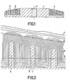
- the base body 1 shows a disk-shaped base body 1 which is symmetrical with respect to the axis of rotation 2.
- This base body 1 has in the area of the focal spot path to be applied cone-shaped end face 3, the shape of which corresponds approximately to the shape of the focal spot web to be applied later and which intersects the axis of rotation 2 at an angle of preferably 70 to 80 °. In principle, however, a circular disk body with non-beveled cylinder surfaces could also be used.
- the base body 1 is provided with a number of grooves 4 which are concentric with the axis of rotation 2 and between which there are concentric webs 5 - hereinafter referred to as lamellae - which extend approximately parallel to the axis of rotation.
- the grooves can be made, for example, by turning.
- the grooves 4 thus produced are then filled with pyrolytic graphite by separating carbon from the gas phase.
- Such deposition processes are known and e.g. in Philips Technical Review, 37th year, No. 8, pages 205 to 213.
- the hot-wall method described therein is preferably used, since it heats up optimally in all phases of the coating, i.e. a homogeneous temperature distribution, guaranteed in the base body.
- it is also possible to use the cold-wall method described in the previous publication because the rotationally symmetrical shape of the base body enables an at least approximately homogeneous temperature distribution (for example with inductive heating) to be achieved.
- Fig. 2 shows a section of the cross section shown in Fig. 1 through the base body 1 after the deposition of pyrolytic graphite.
- the interfaces of the pyrographite layer in the individual phases of the deposition process are indicated by thin lines. It can be seen that these lines follow the contours of the base body more closely, the closer they are to it. That means that on At the beginning of the separation process, the contours of the base body are hardly changed by the coating (only enlarged), while in the final phase, ie after filling the interstices with pyrolytic graphite, they run very differently; the upper boundary 7 of the pyrographite layer 6 is only slightly curved and runs approximately at the same distance from the end faces of the lamellae 5.
- the thermal conductivity perpendicular to the growth direction of the layer is maximal and parallel to it minimal.
- the thin lines therefore also represent the directions in which the heat can be optimally dissipated.
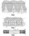
- the grinding plane 8 should lie in the plane of the end faces of the lamellae 5. In the case of lamella thicknesses of approximately 100 .mu.m or in the case of lamellae with pointed or rounded end faces, as shown in FIGS. 3 and 4, it is sufficient for good heat dissipation if the distance between the grinding plane 8 and the end face of the lamellae 10 to 20 % of Ab between the slats.
- the lamellae should be arranged at a millimeter distance (0.1 to a maximum of 4 mm) from one another. The smaller the distance, the shorter the deposition process can take.
- the slats themselves should be as thin as possible (0.1 mm to 3 mm), preferably thinner than the distance between the slats. The thinner the fins compared to their distance, the greater the proportion of pyrolytic graphite in the area of the focal spot path (which improves the thermal conductivity) and the less pyrolytic graphite has to be ground down to achieve good thermal contact with the focal spot path.
- Figure 2 also shows that the areas of greatest thermal conductivity at the bottom of the groove are approximately parallel to it. This means that the heat can be transported very poorly into the base body and released to the outside. As indicated by the line 9, the part of the base body 1 connecting the slats 5 and a small part of the slats themselves must therefore be ground off. A resulting lack of mechanical strength can, if necessary, e.g. be eliminated by a suitable holder enclosing the anode disk.
- the body processed in this way forms (after the application of the heavy metal layer on the end face 8) the anode disk.
- the heat is dissipated mainly in the layer of pyrolytic graphite between the fins.
- the interlocking of the pyrographite layers and the lamellae results in good mechanical strength.
- FIG. 3 and 4 is a section corresponding to FIG. 2 of a base body coated with pyrographite shown, however, the slats are tapered (Fig. 3) or rounded (Fig. 4) and each protrude equally far from the base body 1.
- the same reference numerals are used again as in FIG. 2.
- the grinding plane for applying the heavy metal web must be inclined in accordance with the position of the focal spot web. This has the additional advantage that the areas of greatest thermal conductivity of the pyrolytic graphite layer 6 are always cut at an angle other than zero.
- a one-piece base body was assumed, in which the lamella structure was produced by mechanical processing.
- 5 shows a base body consisting of several parts, which is particularly easy to manufacture.
- This base body is produced by winding two graphite foils of different widths, which are available on the market, for example, under the name “Sigraflex” from Sigri and under the name “Papyex” from Irish Carbone AG. The winding takes place in such a way that the two graphite foils come exactly to cover with their lower longitudinal edge.
- Coating with pyrolytic graphite is carried out as described in connection with FIG. 1.
- the lamellae While in the previously described embodiments the lamellae were concentric to the axis of rotation 2, they run radially in the embodiment shown in FIG. 6 in plan view and in FIG. 7 (in part) in side view, ie they lie in the planes containing the axis of rotation.
- the slats could be produced by milling a circular body, but this would result in a considerable amount of work.
- the lamellae 5 are flat plates which are attached to the outer circumference of a circular body 14 in a uniformly distributed manner. The slats can be clamped in grooves 15 provided on the circumference of the circular body 14 of shallow depth. The subsequent pyrographite coating then further solidifies the entire system.
- the fins can be made of electrographite, pyrolytic graphite, graphite foils, metal or metal carbide foils.
- the coating with pyrolytic graphite would also have to be partially removed again here, as indicated in the drawing, along lines 9 and 8 and expediently also on the outer circumference of the disk.
- the focal spot path can be arranged on the one hand on the outer periphery of the pane, but also on a (cone-shaped) end face of the pane body coated with pyrolytic graphite.
- the cut e.g. along line 8 must not run perpendicular to the plane of the drawing, but at an angle along a conical surface that would intersect the growth direction of the pyrographite coating at an angle other than 90 °.
Landscapes
- Carbon And Carbon Compounds (AREA)
- Continuous Casting (AREA)
- Analysing Materials By The Use Of Radiation (AREA)
- Ceramic Products (AREA)
Applications Claiming Priority (2)
| Application Number | Priority Date | Filing Date | Title |
|---|---|---|---|
| DE19803041249 DE3041249A1 (de) | 1980-11-03 | 1980-11-03 | Koerper, der wenigstens teilweise aus pyrolytischem graphit besteht, insbesondere anodenscheibe fuer eine drehanoden-roentgenroehre und verfahren zu seiner herstellung |
| DE3041249 | 1980-11-03 |
Publications (2)
| Publication Number | Publication Date |
|---|---|
| EP0051335A1 true EP0051335A1 (fr) | 1982-05-12 |
| EP0051335B1 EP0051335B1 (fr) | 1985-07-03 |
Family
ID=6115757
Family Applications (1)
| Application Number | Title | Priority Date | Filing Date |
|---|---|---|---|
| EP81201193A Expired EP0051335B1 (fr) | 1980-11-03 | 1981-10-28 | Méthode de fabrication d'un disque anodique pour un tube à rayons X à anode tournante |
Country Status (4)
| Country | Link |
|---|---|
| US (1) | US4741011A (fr) |
| EP (1) | EP0051335B1 (fr) |
| JP (1) | JPS57107545A (fr) |
| DE (2) | DE3041249A1 (fr) |
Cited By (1)
| Publication number | Priority date | Publication date | Assignee | Title |
|---|---|---|---|---|
| WO2011001325A1 (fr) * | 2009-06-29 | 2011-01-06 | Koninklijke Philips Electronics N.V. | Élément de disque d'anode comprenant un revêtement conducteur |
Families Citing this family (1)
| Publication number | Priority date | Publication date | Assignee | Title |
|---|---|---|---|---|
| US7858384B2 (en) * | 2005-04-29 | 2010-12-28 | Kimberly-Clark Worldwide, Inc. | Flow control technique for assay devices |
Citations (1)
| Publication number | Priority date | Publication date | Assignee | Title |
|---|---|---|---|---|
| FR2065293A5 (fr) * | 1969-10-11 | 1971-07-23 | Siemens Ag |
Family Cites Families (4)
| Publication number | Priority date | Publication date | Assignee | Title |
|---|---|---|---|---|
| US3819971A (en) * | 1972-03-22 | 1974-06-25 | Ultramet | Improved composite anode for rotating-anode x-ray tubes thereof |
| FR2242775A1 (en) * | 1973-08-31 | 1975-03-28 | Radiologie Cie Gle | Rotary anode for X-ray tubes - using pseudo-monocrystalline graphite for better heat conduction |
| US4335327A (en) * | 1978-12-04 | 1982-06-15 | The Machlett Laboratories, Incorporated | X-Ray tube target having pyrolytic amorphous carbon coating |
| DE2910138A1 (de) * | 1979-03-15 | 1980-09-25 | Philips Patentverwaltung | Anodenscheibe fuer eine drehanoden- roentgenroehre |
-
1980
- 1980-11-03 DE DE19803041249 patent/DE3041249A1/de not_active Withdrawn
-
1981
- 1981-10-28 DE DE8181201193T patent/DE3171251D1/de not_active Expired
- 1981-10-28 EP EP81201193A patent/EP0051335B1/fr not_active Expired
- 1981-10-29 US US06/316,165 patent/US4741011A/en not_active Expired - Fee Related
- 1981-11-04 JP JP56177004A patent/JPS57107545A/ja active Pending
Patent Citations (1)
| Publication number | Priority date | Publication date | Assignee | Title |
|---|---|---|---|---|
| FR2065293A5 (fr) * | 1969-10-11 | 1971-07-23 | Siemens Ag |
Cited By (2)
| Publication number | Priority date | Publication date | Assignee | Title |
|---|---|---|---|---|
| WO2011001325A1 (fr) * | 2009-06-29 | 2011-01-06 | Koninklijke Philips Electronics N.V. | Élément de disque d'anode comprenant un revêtement conducteur |
| US8948344B2 (en) | 2009-06-29 | 2015-02-03 | Koninklijke Philips N.V. | Anode disk element comprising a conductive coating |
Also Published As
| Publication number | Publication date |
|---|---|
| EP0051335B1 (fr) | 1985-07-03 |
| DE3041249A1 (de) | 1982-06-09 |
| DE3171251D1 (en) | 1985-08-08 |
| JPS57107545A (en) | 1982-07-05 |
| US4741011A (en) | 1988-04-26 |
Similar Documents
| Publication | Publication Date | Title |
|---|---|---|
| DE69433547T2 (de) | Gemustertes schleifmittel und verfahren | |
| DE1951383C3 (de) | Röntgenröhren-Drehanode mit einem Verbundkörper aus einem Schwermetallteil und wenigstens einem Graphitteil und Verfahren zu ihrer Herstellung | |
| EP0015993B1 (fr) | Disque pour frein à disque, en particulier pour frein de véhicule | |
| DE2443354C3 (de) | Drehanodenscheibe für eine Röntgenröhre und Verfahren zu ihrer Herstellung | |
| DE2451485A1 (de) | Verfahren zur metallisierung von ungebranntem keramikmaterial | |
| EP0062764B1 (fr) | Procédé pour la fabrication d'une plaque comprenant un film mince métallique magnétique | |
| DE3113559A1 (de) | Magnetisches aufzeichnungsmedium und vorrichtung zur herstellung desselben | |
| EP0111728A2 (fr) | Procédé et dispositif pour la fabrication de produits en forme de bandes ou de feuilles | |
| EP0016485B1 (fr) | Anode en forme de disque pour tube à rayons X avec anode tournante | |
| DE3145648A1 (de) | Halbleiteranordnung | |
| AT393568B (de) | Magnetwandlerkopf | |
| DE10042132A1 (de) | Selektives Randschichtschmelzen | |
| DE2350807B2 (de) | Röntgenröhre mit einer flüssigkeitsgekühlten Anode | |
| DE2425464B2 (de) | Verfahren zur Herstellung von Dünnschicht-Aperturblenden für Korpuskularstrahlgeräte | |
| DE3408848C2 (de) | Verfahren zur Herstellung von Vielkanalplatten | |
| DE69004506T2 (de) | Verfahren zur Herstellung eines geteilten kreisförmigen Ringes. | |
| EP0051335B1 (fr) | Méthode de fabrication d'un disque anodique pour un tube à rayons X à anode tournante | |
| DE9106611U1 (de) | Kupplungsscheibe | |
| DE69608479T2 (de) | Vorrichtung und Verfahren zur Herstellung von frei stehenden Diamanten | |
| DE2231269A1 (de) | Verfahren zur herstellung eines spaltsiebes | |
| DE1275699B (de) | Verfahren zur Herstellung einer magnetischen Duennschichtanordnung | |
| DE3013441C2 (de) | Anodenteller für eine Drehanoden-Röntgenröhre und Verfahren zu seiner Herstellung | |
| DE2739530A1 (de) | Verfahren zur bildung einzelner photodetektorelemente auf einem substrat sowie nach diesem verfahren hergestellte photodetektoranordnung | |
| EP0010222A1 (fr) | Plaque de commande pour un écran plat à plasma de reproduction d'image | |
| DE68908908T2 (de) | Vorrichtung zum Trennen von Uranisotopen. |
Legal Events
| Date | Code | Title | Description |
|---|---|---|---|
| PUAI | Public reference made under article 153(3) epc to a published international application that has entered the european phase |
Free format text: ORIGINAL CODE: 0009012 |
|
| AK | Designated contracting states |
Designated state(s): DE FR GB IT |
|
| 17P | Request for examination filed |
Effective date: 19820726 |
|
| RAP1 | Party data changed (applicant data changed or rights of an application transferred) |
Owner name: N.V. PHILIPS' GLOEILAMPENFABRIEKEN Owner name: PHILIPS PATENTVERWALTUNG GMBH |
|
| GRAA | (expected) grant |
Free format text: ORIGINAL CODE: 0009210 |
|
| AK | Designated contracting states |
Designated state(s): DE FR GB IT |
|
| PG25 | Lapsed in a contracting state [announced via postgrant information from national office to epo] |
Ref country code: IT Free format text: LAPSE BECAUSE OF FAILURE TO SUBMIT A TRANSLATION OF THE DESCRIPTION OR TO PAY THE FEE WITHIN THE PRESCRIBED TIME-LIMIT;WARNING: LAPSES OF ITALIAN PATENTS WITH EFFECTIVE DATE BEFORE 2007 MAY HAVE OCCURRED AT ANY TIME BEFORE 2007. THE CORRECT EFFECTIVE DATE MAY BE DIFFERENT FROM THE ONE RECORDED. Effective date: 19850703 |
|
| REF | Corresponds to: |
Ref document number: 3171251 Country of ref document: DE Date of ref document: 19850808 |
|
| ET | Fr: translation filed | ||
| PLBE | No opposition filed within time limit |
Free format text: ORIGINAL CODE: 0009261 |
|
| STAA | Information on the status of an ep patent application or granted ep patent |
Free format text: STATUS: NO OPPOSITION FILED WITHIN TIME LIMIT |
|
| GBPC | Gb: european patent ceased through non-payment of renewal fee | ||
| PG25 | Lapsed in a contracting state [announced via postgrant information from national office to epo] |
Ref country code: FR Free format text: LAPSE BECAUSE OF NON-PAYMENT OF DUE FEES Effective date: 19860630 |
|
| 26N | No opposition filed | ||
| REG | Reference to a national code |
Ref country code: FR Ref legal event code: ST |
|
| PG25 | Lapsed in a contracting state [announced via postgrant information from national office to epo] |
Ref country code: GB Effective date: 19881118 |
|
| PGFP | Annual fee paid to national office [announced via postgrant information from national office to epo] |
Ref country code: DE Payment date: 19881220 Year of fee payment: 8 |
|
| PG25 | Lapsed in a contracting state [announced via postgrant information from national office to epo] |
Ref country code: DE Effective date: 19900703 |