EP0051342B1 - Synthétiseur digital de parole pour plusieurs canaux utilisant des paramètres ajustables - Google Patents
Synthétiseur digital de parole pour plusieurs canaux utilisant des paramètres ajustables Download PDFInfo
- Publication number
- EP0051342B1 EP0051342B1 EP19810201230 EP81201230A EP0051342B1 EP 0051342 B1 EP0051342 B1 EP 0051342B1 EP 19810201230 EP19810201230 EP 19810201230 EP 81201230 A EP81201230 A EP 81201230A EP 0051342 B1 EP0051342 B1 EP 0051342B1
- Authority
- EP
- European Patent Office
- Prior art keywords
- speech
- control
- data
- processing unit
- interpolations
- Prior art date
- Legal status (The legal status is an assumption and is not a legal conclusion. Google has not performed a legal analysis and makes no representation as to the accuracy of the status listed.)
- Expired
Links
- 238000007781 pre-processing Methods 0.000 claims description 10
- 238000000034 method Methods 0.000 claims description 6
- 239000000872 buffer Substances 0.000 description 16
- 230000005540 biological transmission Effects 0.000 description 13
- 238000004364 calculation method Methods 0.000 description 4
- 238000010586 diagram Methods 0.000 description 4
- 230000000694 effects Effects 0.000 description 2
- 230000006978 adaptation Effects 0.000 description 1
- 238000004891 communication Methods 0.000 description 1
- 230000006835 compression Effects 0.000 description 1
- 238000007906 compression Methods 0.000 description 1
- 230000003247 decreasing effect Effects 0.000 description 1
- 230000007812 deficiency Effects 0.000 description 1
- 230000011664 signaling Effects 0.000 description 1
Images



Classifications
-
- G—PHYSICS
- G10—MUSICAL INSTRUMENTS; ACOUSTICS
- G10L—SPEECH ANALYSIS TECHNIQUES OR SPEECH SYNTHESIS; SPEECH RECOGNITION; SPEECH OR VOICE PROCESSING TECHNIQUES; SPEECH OR AUDIO CODING OR DECODING
- G10L13/00—Speech synthesis; Text to speech systems
- G10L13/02—Methods for producing synthetic speech; Speech synthesisers
- G10L13/04—Details of speech synthesis systems, e.g. synthesiser structure or memory management
- G10L13/047—Architecture of speech synthesisers
Definitions
- the invention relates to a digital multichannel speech synthesizer operating according to the linear-predictive-coding method, comprising:
- a digital multichannel speech synthesizer is according to the invention characterized in that said speech generator in combination with control means are adapted to selectively vary the number of bits involved in the computation of each parameter and/or the number of parameters effective for generating synthesized speech, in dependence on the multichannel load; said control means comprising:
- a multichannel synthesizer structured in accordance with the principles of the present invention inherently has the options to selectively control a) the number of interpolations between successively received samples of speech (set of parameters), and b) the number and/or "width dimension" (number of bits) of the parameters (filter coefficients) included in the respective speech samples. Therefore the quality of the synthesized speech can be improved when the traffic load is lowered.
- the above embodiment is illustrative of a specific structure for the implementation of interpolation processes wherein on the basis of knowledge about the time available between successively received samples of speech, a correspondingly varied number of interpolations is carried out.
- the further embodiment described above is illustrative of a specific structure by which on the basis of knowledge about the traffic load of the multichannel transmission path, (and therefore on the basis of available transmission time) the number of coefficients and/or the number of bits per coefficient can be correspondingly varied.
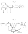
- Fig. 1 is a general block diagram of a speech synthesizer.
- the adjusting parameters for the device are designated by the letters a, b, c and d.
- the circuit comprises a digital noise source 1, which generates white noise for unvoiced speech components, and a digital pitch generator 2, which generates the fundamental frequency for voiced speech components and is adjusted according to parameter a.
- the choice between generators 1 and 2 is made by switch 3 as controlled by parameter b.
- the digital signal is applied successively to an adjustable digital ladder filter 4, controlled by parameter c, and a digital volume regulator 5, controlled by parameter d.
- a digital-to-analog converter 6 converts the digital signal into an analog signal.
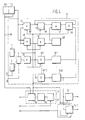
- Fig. 2 is a block diagram of the device according to the invention.
- a digital input signal incorporating the parameters a, b, c and d is applied to input 7 of the speech synthesizer and led to a buffer 8.
- the parameters a, b, c and d have been determined by the "linear predictive coding" method and can come from a storage medium, in the case of a message that has to be repeated regularly or from a transmission line.
- a preprocessing unit 9 ensures the reading of the parameters and their storage in portion 10.1 of store 10, the interpolation of two successive groups of parameters, the transfer of the interpolation results to other parts of the circuit and the passing of control data to the central processing unit 11.
- the data stored in store portion 10.1 can be transferred to a second store portion 10.2, when the preceding data stored in 10.2 have been processed. Processing takes place in a computing unit 12, which employs the interpolated data for adjusting the ladder filter (Fig. 1; 4) incorporated in the computing unit. In the meantime store portion 10.1 is filled again.
- the computing unit 12 of this embodiment can compute the digital speech signals for 16 speech channels simultaneously. These digital speech signals are stored in "first-in-first-out" buffers 13.1... 13.16 (one signal per channel) and then led to digital-to-analog converters 6.1... 6.16, respectively.
- the computing unit 12 is controlled in conformity with fixed rules by a control unit 14, which receives its instructions from the central processing unit 11.
- Fig. 3 illustrates a preferred embodiment of the pre-processing unit 9 according to the invention, and store portion 10.1.
- the data coming from the buffer (Fig. 2; 8) are led to a series-to-parallel converter 15.
- the discriminator 16 infers from the first few bits of a 24-bit frame whether this frame contains speech data or control information, in which cases a data buffer 17 or a control buffer 18 is opened, respectively.
- the speech data are led from the data buffer 17 via a data bus 19 to a microprocessor 20, which is connected to the central processing unit (Fig. 2; 11) via a control bus 21 and an address bus 22.
- Store 23 (RAM) and decoding store 24 (ROM) are also connected to this data bus.
- the circuit comprises an adder-multiplier 25 for carrying out parts of interpolation calculations.
- the group of parameters comprises, as has already been observed, the following four:
- the function of the speech data portion of the circuit of Fig. 3 is described as separating the parameters a, b, c and d and interpolating the parameters c and d. Interpolation is necessary, because the speech information arrives in bursts and because annoying clicks could occur without interpolation.
- the coefficients and are generated by the microprocessor 20.
- the reflection coefficients interpolated on the basis of rule (1) and the interpolated volume are led to store 10.1.
- the pre-processing unit comprises means for adjusting the quality of the speech reproduced according to the degree of occupation of the transmission medium. Therefore, at the transmitting end, relevant data are sent along with the control signals. These data are interpreted in the function decoder 28.
- the circuit comprises a register 29, for recording the number of interpolations to be carried out by the microprocessor 20 on the unvoiced part of the speech, and a register 30, which has an analogous function with regard to the voiced part of the speech. Registers 29 and 30 are connected to ROM store 31, which converts the number of interpolations to be carried out into a signal for positioning counter 32, stepping in synchronism with a counter incorporated in microprocessor 20.
- the position of counter 32 is passed to a fraction table 33 (ROM), connected via a selector 34 to control bus 21 and address bus 22. Under the control of the central processing unit (Fig. 2; 11), the number of interpolations to be carried out by the microprocessor 20 can be fixed.
- the circuit of Fig. 3 also contains registers 35 and 36 for recording adjusting data for the adjustable filter incorporated in the computing unit (Fig. 2; 12). The adjusting data for unvoiced speech are stored in register 35, those for voiced speech in register 36.
- a ROM 37 converts the adjusting data into positioning data for counter 38. Via selector 39 the counter position is passed to buses 21 and 22, after which the number of calculations to be carried out by the control unit (Fig. 2: 14) is fixed under the control of the central processing unit (Fig. 2; 11).
- the circuit may contain a register 40 for recording a signal indicating that the next one or two frames contain no speech.
- the relevant data can be passed via selector 41 and buses 21 and 22 to the central processing unit (Fig. 2; 11), so that the computing unit (Fig. 2; 12) can spend the time thus saved in dealing with other channels.
- the circuit may comprise a register 42 and a selector 43 for recording the signal indicating that one or two new frames contain the same information as the preceding frame, so that the new frames need not be transmitted. Because the preceding frame is in the buffer (Fig. 2; 8) for interpolation purposes, repetition will suffice, so that transmission capacity is saved. In an analogous way information concerning the degree of compression and expansion of the speech signal can be received and handled.
- Fig. 4 illustrates a preferred elaboration of store 10.2, computing unit 12, buffers 13 and control unit 14.
- the data stored in 10.1 (Fig. 2) are transferred to store 10.2 under the control of the central processing unit 11.
- the data stored in 10.2, containing the information for computing the digital signal to be supplied to the buffers 13, are led to multipliers 44 and 45 working in parallel, adder-subtractor 46, AND-circuit 47 and D-flip-flop 48.
- Selector 49 determines the number of bits to be calculated per PCM-word and a round-off factor.
- D-flip-flop 50 ensures in a well-known manner the adaptation to bus traffic.
- the results of a first calculation are written, for sixteen separate channels, in buffers 51, from which they can be output via D-flip-flops 52.
- the voiced/ unvoiced and pitch data are sent via output 26 to electronic switch 3 and via output 27 to generator 2, respectively, and combined by means of D-flip-flop 53 with the digital signal to be calculated.
- the whole algorithm can be represented by the following formulae: and in which and
- Multipliers 44 and 45 ensure the multiplications and adder-subtractor 46 carries out the adding and subtracting operations.
- the intermediate results of the operations are put away, every time, in the 51-buffer associated with the channel dealt with. Every time one sample has been calculated, its value is multiplied by the volume factor C n .
- the various operations carried out on the data from store 10.2 are controlled by a programmable store (PROM) 54, which, under the control of a counter 55, makes a step every time after the calculation of one PCM-sample for each of the 16 channels.
- the stepping of counter 55 is timed by clock 56.
- Store 54 supplies the data required for carrying out the various operations via a control bus 57 and the address data for store 10 via address bus 58.
- the last instruction in store 54 relates to writing the calculated final results in buffers 13 and signalling to the central processing unit 11 (Fig. 2) that the programme has finished. Then, under the control of central processing unit 11 (Fig. 2), a fresh set of data is transferred from store 10.1 to store 10.2, clock 56 being started in order to carry out again the programme contained in store 54.
- the data produced by the programme will only be stored when the central processing unit 11 (Fig. 2) has found that the buffers 13 are not full. After the data have been stored in buffers 13, the programme is started again under the control of the central processing unit 11.
- the invention provides a relatively simple device for generating, from an input signal produced by the LPC-method referred to hereinabove, an analog signal for a large number of channels.
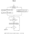
- the pre-processing unit 9 and the central processing unit 11 comprise microcomputers, for which the flow-charts are given in Figs. 5 and 6, respectively.
- the arrangement is not relevant for a good understanding of the invention, so that the flow-chart need not be described in detail.
Landscapes
- Engineering & Computer Science (AREA)
- Computational Linguistics (AREA)
- Health & Medical Sciences (AREA)
- Audiology, Speech & Language Pathology (AREA)
- Human Computer Interaction (AREA)
- Physics & Mathematics (AREA)
- Acoustics & Sound (AREA)
- Multimedia (AREA)
- Compression, Expansion, Code Conversion, And Decoders (AREA)
Claims (3)
Applications Claiming Priority (2)
| Application Number | Priority Date | Filing Date | Title |
|---|---|---|---|
| NL8005989A NL8005989A (nl) | 1980-10-31 | 1980-10-31 | Inrichting voor digitale spraaksynthese voor meer kanalen met instelbare parameters. |
| NL8005989 | 1980-10-31 |
Publications (2)
| Publication Number | Publication Date |
|---|---|
| EP0051342A1 EP0051342A1 (fr) | 1982-05-12 |
| EP0051342B1 true EP0051342B1 (fr) | 1986-01-29 |
Family
ID=19836096
Family Applications (1)
| Application Number | Title | Priority Date | Filing Date |
|---|---|---|---|
| EP19810201230 Expired EP0051342B1 (fr) | 1980-10-31 | 1981-10-30 | Synthétiseur digital de parole pour plusieurs canaux utilisant des paramètres ajustables |
Country Status (3)
| Country | Link |
|---|---|
| EP (1) | EP0051342B1 (fr) |
| DE (1) | DE3173669D1 (fr) |
| NL (1) | NL8005989A (fr) |
Cited By (1)
| Publication number | Priority date | Publication date | Assignee | Title |
|---|---|---|---|---|
| CN101847404A (zh) * | 2010-03-18 | 2010-09-29 | 北京天籁传音数字技术有限公司 | 一种实现音频变调的方法和装置 |
Family Cites Families (3)
| Publication number | Priority date | Publication date | Assignee | Title |
|---|---|---|---|---|
| US3715512A (en) * | 1971-12-20 | 1973-02-06 | Bell Telephone Labor Inc | Adaptive predictive speech signal coding system |
| US3975587A (en) * | 1974-09-13 | 1976-08-17 | International Telephone And Telegraph Corporation | Digital vocoder |
| IT1165641B (it) * | 1979-03-15 | 1987-04-22 | Cselt Centro Studi Lab Telecom | Sintetizzatore numerico multicanale della voce |
-
1980
- 1980-10-31 NL NL8005989A patent/NL8005989A/nl not_active Application Discontinuation
-
1981
- 1981-10-30 EP EP19810201230 patent/EP0051342B1/fr not_active Expired
- 1981-10-30 DE DE8181201230T patent/DE3173669D1/de not_active Expired
Cited By (2)
| Publication number | Priority date | Publication date | Assignee | Title |
|---|---|---|---|---|
| CN101847404A (zh) * | 2010-03-18 | 2010-09-29 | 北京天籁传音数字技术有限公司 | 一种实现音频变调的方法和装置 |
| CN101847404B (zh) * | 2010-03-18 | 2012-08-22 | 北京天籁传音数字技术有限公司 | 一种实现音频变调的方法和装置 |
Also Published As
| Publication number | Publication date |
|---|---|
| NL8005989A (nl) | 1982-05-17 |
| DE3173669D1 (en) | 1986-03-13 |
| EP0051342A1 (fr) | 1982-05-12 |
Similar Documents
| Publication | Publication Date | Title |
|---|---|---|
| KR100417635B1 (ko) | 광대역 신호들 코딩에서 적응성 대역폭 피치 검색 방법 및디바이스 | |
| US4907277A (en) | Method of reconstructing lost data in a digital voice transmission system and transmission system using said method | |
| EP0379587B1 (fr) | Appareil codeur/decodeur | |
| US6484140B2 (en) | Apparatus and method for encoding a signal as well as apparatus and method for decoding signal | |
| EP0966793B1 (fr) | Appareil et procede de codage audio | |
| US5668925A (en) | Low data rate speech encoder with mixed excitation | |
| WO1980002211A1 (fr) | Systeme predictif de codage de la parole a excitation residuelle | |
| EP0657874B1 (fr) | Codeur de voix et procédé pour chercher des livres de codage | |
| EP0801377B1 (fr) | Appareil pour coder un signal | |
| US4945565A (en) | Low bit-rate pattern encoding and decoding with a reduced number of excitation pulses | |
| CA1144650A (fr) | Codage de signaux predictifs avec quantification a division | |
| EP0396121B1 (fr) | Système pour le codage de signaux audio à large bande | |
| US5649051A (en) | Constant data rate speech encoder for limited bandwidth path | |
| JP3616432B2 (ja) | 音声符号化装置 | |
| EP0552927A2 (fr) | Méthode de prédiction de forme d'onde pour un signal acoustique et dispositif de codage et décodage correspondant | |
| EP0051342B1 (fr) | Synthétiseur digital de parole pour plusieurs canaux utilisant des paramètres ajustables | |
| US6016468A (en) | Generating the variable control parameters of a speech signal synthesis filter | |
| US4908863A (en) | Multi-pulse coding system | |
| EP0162585B1 (fr) | Codeur capable de supprimer l'interaction entre trames adjacentes | |
| EP0729133B1 (fr) | Détermination de l'amplification pour la période du signal dans le codage d'un signal de parole | |
| US5519394A (en) | Coding/decoding apparatus and method | |
| EP0333425A2 (fr) | Codage de la parole | |
| JP3092124B2 (ja) | 適応変換符号化の方法及び装置 | |
| JPH05323999A (ja) | 音声復号装置 | |
| JPH04301900A (ja) | 音声符号化装置 |
Legal Events
| Date | Code | Title | Description |
|---|---|---|---|
| PUAI | Public reference made under article 153(3) epc to a published international application that has entered the european phase |
Free format text: ORIGINAL CODE: 0009012 |
|
| AK | Designated contracting states |
Designated state(s): BE DE FR GB SE |
|
| 17P | Request for examination filed |
Effective date: 19821112 |
|
| GRAA | (expected) grant |
Free format text: ORIGINAL CODE: 0009210 |
|
| AK | Designated contracting states |
Designated state(s): BE DE FR GB SE |
|
| REF | Corresponds to: |
Ref document number: 3173669 Country of ref document: DE Date of ref document: 19860313 |
|
| ET | Fr: translation filed | ||
| PLBE | No opposition filed within time limit |
Free format text: ORIGINAL CODE: 0009261 |
|
| STAA | Information on the status of an ep patent application or granted ep patent |
Free format text: STATUS: NO OPPOSITION FILED WITHIN TIME LIMIT |
|
| 26N | No opposition filed | ||
| PG25 | Lapsed in a contracting state [announced via postgrant information from national office to epo] |
Ref country code: GB Effective date: 19881030 |
|
| PG25 | Lapsed in a contracting state [announced via postgrant information from national office to epo] |
Ref country code: SE Effective date: 19881031 Ref country code: BE Effective date: 19881031 |
|
| BERE | Be: lapsed |
Owner name: TELEGRAFIE EN TELEFONIE Effective date: 19881031 Owner name: STAAT DER NEDERLANDEN STAATSBEDRIJF DER POSTERIJE Effective date: 19881031 |
|
| PG25 | Lapsed in a contracting state [announced via postgrant information from national office to epo] |
Ref country code: FR Free format text: LAPSE BECAUSE OF NON-PAYMENT OF DUE FEES Effective date: 19890630 |
|
| PG25 | Lapsed in a contracting state [announced via postgrant information from national office to epo] |
Ref country code: DE Effective date: 19890701 |
|
| GBPC | Gb: european patent ceased through non-payment of renewal fee | ||
| REG | Reference to a national code |
Ref country code: FR Ref legal event code: ST |
|
| EUG | Se: european patent has lapsed |
Ref document number: 81201230.0 Effective date: 19890614 |