EP0051344A1 - Assemblage des aimants pour un véhicule d'inspection de canalisation - Google Patents
Assemblage des aimants pour un véhicule d'inspection de canalisation Download PDFInfo
- Publication number
- EP0051344A1 EP0051344A1 EP81300112A EP81300112A EP0051344A1 EP 0051344 A1 EP0051344 A1 EP 0051344A1 EP 81300112 A EP81300112 A EP 81300112A EP 81300112 A EP81300112 A EP 81300112A EP 0051344 A1 EP0051344 A1 EP 0051344A1
- Authority
- EP
- European Patent Office
- Prior art keywords
- pipeline
- coupling members
- vehicle
- magnetic
- inspection vehicle
- Prior art date
- Legal status (The legal status is an assumption and is not a legal conclusion. Google has not performed a legal analysis and makes no representation as to the accuracy of the status listed.)
- Granted
Links
- 238000007689 inspection Methods 0.000 title claims abstract description 26
- 230000000712 assembly Effects 0.000 title description 12
- 238000000429 assembly Methods 0.000 title description 12
- 230000005291 magnetic effect Effects 0.000 claims abstract description 41
- 239000011888 foil Substances 0.000 claims abstract description 17
- 230000008878 coupling Effects 0.000 claims description 38
- 238000010168 coupling process Methods 0.000 claims description 38
- 238000005859 coupling reaction Methods 0.000 claims description 38
- 230000004907 flux Effects 0.000 claims description 10
- 239000012530 fluid Substances 0.000 claims description 3
- 239000002184 metal Substances 0.000 claims description 3
- 238000007789 sealing Methods 0.000 claims description 3
- 239000000203 mixture Substances 0.000 claims description 2
- 230000005294 ferromagnetic effect Effects 0.000 abstract description 3
- 229920001971 elastomer Polymers 0.000 description 8
- 239000005060 rubber Substances 0.000 description 8
- 238000010276 construction Methods 0.000 description 4
- 230000007547 defect Effects 0.000 description 3
- 239000013589 supplement Substances 0.000 description 3
- 230000001419 dependent effect Effects 0.000 description 2
- 230000000694 effects Effects 0.000 description 2
- 239000007788 liquid Substances 0.000 description 2
- 238000003491 array Methods 0.000 description 1
- 238000001514 detection method Methods 0.000 description 1
- 239000003302 ferromagnetic material Substances 0.000 description 1
- 230000001939 inductive effect Effects 0.000 description 1
- 230000002787 reinforcement Effects 0.000 description 1
- 230000035939 shock Effects 0.000 description 1
- 239000000725 suspension Substances 0.000 description 1
- 238000003466 welding Methods 0.000 description 1
Images

Classifications
-
- G—PHYSICS
- G01—MEASURING; TESTING
- G01N—INVESTIGATING OR ANALYSING MATERIALS BY DETERMINING THEIR CHEMICAL OR PHYSICAL PROPERTIES
- G01N27/00—Investigating or analysing materials by the use of electric, electrochemical, or magnetic means
- G01N27/72—Investigating or analysing materials by the use of electric, electrochemical, or magnetic means by investigating magnetic variables
- G01N27/82—Investigating or analysing materials by the use of electric, electrochemical, or magnetic means by investigating magnetic variables for investigating the presence of flaws
-
- G—PHYSICS
- G01—MEASURING; TESTING
- G01M—TESTING STATIC OR DYNAMIC BALANCE OF MACHINES OR STRUCTURES; TESTING OF STRUCTURES OR APPARATUS, NOT OTHERWISE PROVIDED FOR
- G01M3/00—Investigating fluid-tightness of structures
- G01M3/005—Investigating fluid-tightness of structures using pigs or moles
Definitions
- This invention relates to pipeline vehicles intended for the detection of defects in the walls of pipeline constructed of ferro-magnetic material when traversing the inside of the pipeline, and in particular to magnet assemblies for such vehicles.
- a complete pipeline inspection vehicle normally consists of several elements or modules flexibly linked together by towing couplings and operating as a single train.
- pipeline inspection vehicles of the kind with which the present invention is particularly concerned operate by permeating an area of the pipe wall with magnetic flux from spaced arrays of magnets of a magnet assembly resiliently mounted on one of the vehicle modules and detecting anomalies in the magnetic field- adjacent to the pipe wall caused by flux leakage around defects.
- the motive power for pipeline vehicles is normally provided by fitting cup rubbers to one or more modules of the vehicle train. These cup rubbers fit closely against the pipe wall, creating a fluid tight seal, and ensure that the vehicle train is driven forward by the flow of liquid or gas in the pipeline.
- drive cup rubbers may be mounted in the module containing the magnet assemblies with certain advantages hereinafter described, or on a separate 'traction' module. At least two drive cup rubbers are normally provided, to provide continuity of driving impulse when one cup rubber is abreast of a branch pipe or other discontinuity in the pipe wall profile.
- At least one of the drive cup rubbers is notmally mounted on the leading module of the train.
- the second drive cup rubber may also be mounted on this module, spaced axially from it by at least one pipe diameter, or mounted on the second or subsequent module.
- the magnet assembly module may be the leading element in a multi-module train, if it is fitted with a drive cup, or it may operate behind a separate traction module.
- the coupling member that couples each magnet to the pipe wall has a major effect on the performance of the magnet system.
- the requirements are that it should wear well, and that the magnetic reluctance should be low, and should not vary significantly when traversing obstructions or welds and it should not induce excessive drag or resistance to motion of the pipeline vehicle. _These functions may be fulfilled by coupling members constructed of wire bristles or metal foils as described in our co-pending British Patent Application No. 2,034,122A.
- An object of the present invention is to provide a magnetic pipeline inspection vehicle, and magnet assemblies for such vehicles, less subject to the aforesaid disadvantages.
- the return-path member is an annular member forming a rigid part of the vehicle body, and said magnets and coupling members are rigidly but detachably secured to the annular member, coupling members also provide at least part of the means for supporting the vehicle in the pipeline and for maintaining magnetic coupling over regions of changes in pipeline geometry, the nature and/or the stiffness of the coupling members being carefully optimised to give the lowest acceptable levels of;
- the vehicle has, however, been found that, provided the stiffness of the magnetic coupling element (i.e. either the aforesaid bristles or foils) is carefully optimised and made not greater than that necessary to support the vehicle weight, the vehicle has a lower bore-dependent drag or resistance to motion than an equivalent vehicle with articulating magnet assemblies of equivalent performance.
- the stiffness of the magnetic coupling element i.e. either the aforesaid bristles or foils
- a further alternative in accordance with the invention which allows the magnetic inspection vehicle to be the leading element in a multi-vehicle train, is to fit flexible cup-shaped sealing members to the vehicle.
- these cup members are normally used on pipeline vehicles or vehicle trains to provide the traction element in the train.
- the individual bristle or foil elements are the only element that responds to bore variations or steps. These have low mass. Hence the disadvantage of the high unsprung weight associated with articulating magnet assemblies is avoided without any penalty in respect of bore-dependent drag.
- the magnetic coupling element may be made even less stiff to optimise the magnetic and low drag characteristics above, the weight of the vehicle being carried mainly by wheels attached to the vehicle running along the inside wall of the pipe.
- a further alternative in accordance with the invention is to use a mixture of stiff and flexible bristles or foils to carry the weight of the vehicle and to maintain magnetic coupling over regions of changes in pipeline geometry, e.g. pipe ovality or bends.
- a further alternative in accordance with the invention which allows the magnetic inspection vehicle to be the leading element in a multi-vehicle train, is to fit flexible cup-shaped sealing members to the vehicle.
- These cup members are normally used on pipeline vehicles or vehicle trains to provide the traction element in the train in that they fit closely against the pipe wall and create a seal with the wall surface to ensure that the vehicles are driven forward by the flow of gas or liquid in the pipeline.
- they When fitted to a magnetic inspection vehicle of annular construction, they also provide an element of radial support to supplement that provided by the bristles or foils.
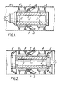
- the magnet assembly for this particular from of magnetic pipeline inspection vehicle comprises an arrangement of permanent magnets 2 of opposite polarity fitted, respectively, at each end of an annular c flur return path body 3 of the magnetic circuit.
- a flux coupling assembly 4 consisting either of ferro-magnetic bristles or foils (as described in said co-pending U.K. Patent Application 2,034,122A) is mounted externally to sach magnet and bridges the annular gap between the magnets and the wall of the ferro-magnetic pipeline 5 whereby to induce a relatively strong magnetic field in that region of the pipeline wall under examination.
- the magnetic lines of force are contrained within that region, but where a fault or defect occurs there is a higher leakage field which is detected by sensors in a plurality of detector modules 6 which are carried by sledge units 7.
- the bristles are manufactured so that the external diameter of the coupling assembly is greater than the maximum pipe bore to be encountered.
- the bristles accordingly are deflected (as shown) towards the rear of the inspection vehicle when the vehicle is moving forward in the pipeline.
- the bristles (or foils) of the coupling assembly 4 are proportioned to be as long as possible in the radial direction, consistent with the provision of magnets and magnetic return path of adequate strength and cross-section.
- the total bristle (or foil) stiffness in this example should be adequate to support the weight of the inspection vehicle and adequately control its attitude when traversing bends, but the assembly should have sufficient flexibility to give a small variation in drag when moving in the axial direction through pipelines of varying wall thickness.
- this magnetic pipeline inspection vehicle is also equipped to allow it to be the leading element in a multi-vehicle train and for this purpose is provided with flexible cup-shaped discs 8 which provide a seal with the pipeline wall enabling the vehicle to be driven forward by the flow of fluid in the pipeline.
- the discs 8 also provide an element of radial support for the weight of the vehicle to supplement that provided by the bristles or foils 4 which can then be relatively less stiff than in the first example whereby to optimise the magnetic coupling characteristics.
- the bristles or foils can again be relatively less stiff than in the first example, and the weight of the vehicle shared by them and a plurality of spring-loaded wheels 9 which are attached to the vehicle and run along the inside wall of the pipeline.
- the arrangement of magnets 2 and bristle or foil magnetic coupling assemblies 4 may be in the form of construction shown in either Figure 4 or Figure 5.
- the magnets 2a and coupling assemblies 4a are of annular form rigidly mounted on the flux return path body 3
- a plurality of magnets 2b and coupling assemblies 4b are rigidly mounted on facets of the flux return path body 3 extending radially outwardly therefrom.
Landscapes
- General Physics & Mathematics (AREA)
- Physics & Mathematics (AREA)
- Chemical & Material Sciences (AREA)
- Chemical Kinetics & Catalysis (AREA)
- Electrochemistry (AREA)
- Health & Medical Sciences (AREA)
- Life Sciences & Earth Sciences (AREA)
- Analytical Chemistry (AREA)
- Biochemistry (AREA)
- General Health & Medical Sciences (AREA)
- Immunology (AREA)
- Pathology (AREA)
- Investigating Or Analyzing Materials By The Use Of Magnetic Means (AREA)
Applications Claiming Priority (2)
| Application Number | Priority Date | Filing Date | Title |
|---|---|---|---|
| GB8033618A GB2086051B (en) | 1980-10-17 | 1980-10-17 | Pipeline inspection vehicle |
| GB8033618 | 1980-10-17 |
Publications (2)
| Publication Number | Publication Date |
|---|---|
| EP0051344A1 true EP0051344A1 (fr) | 1982-05-12 |
| EP0051344B1 EP0051344B1 (fr) | 1984-07-18 |
Family
ID=10516751
Family Applications (1)
| Application Number | Title | Priority Date | Filing Date |
|---|---|---|---|
| EP81300112A Expired EP0051344B1 (fr) | 1980-10-17 | 1981-01-12 | Assemblage des aimants pour un véhicule d'inspection de canalisation |
Country Status (9)
| Country | Link |
|---|---|
| US (1) | US4447777A (fr) |
| EP (1) | EP0051344B1 (fr) |
| JP (1) | JPS5769247A (fr) |
| AU (1) | AU523202B2 (fr) |
| CA (1) | CA1185325A (fr) |
| DE (1) | DE3164786D1 (fr) |
| GB (1) | GB2086051B (fr) |
| NO (1) | NO810125L (fr) |
| ZA (1) | ZA81267B (fr) |
Cited By (5)
| Publication number | Priority date | Publication date | Assignee | Title |
|---|---|---|---|---|
| EP0196020A3 (fr) * | 1985-03-27 | 1989-10-25 | Pipetronix GmbH | Véhicule pour tests électromagnétiques de parois de tubes en acier et procédé à cet effet |
| EP0537928A1 (fr) * | 1991-10-14 | 1993-04-21 | British Gas plc | Machine à inspection magnétique |
| WO2006130050A1 (fr) * | 2005-06-03 | 2006-12-07 | Popovich Alexandr Maximilyanov | Systeme magnetique d'un detecteur de defauts a l'interieur de tuyaux |
| WO2007011268A1 (fr) * | 2005-07-19 | 2007-01-25 | Popovich Alexandr Maximilyanov | Section d'un defectoscope interne |
| CN109737310A (zh) * | 2019-01-29 | 2019-05-10 | 陕西泰诺特检测技术有限公司 | 一种用于管道内部检测的电磁检测系统及方法 |
Families Citing this family (44)
| Publication number | Priority date | Publication date | Assignee | Title |
|---|---|---|---|---|
| JPS5915655A (ja) * | 1982-07-20 | 1984-01-26 | Yanmar Diesel Engine Co Ltd | 内燃機関用制御装置の保護装置 |
| JPH0643991B2 (ja) * | 1985-05-30 | 1994-06-08 | 株式会社検査技研 | 管内部移動・芯出し用治具 |
| US4789827A (en) * | 1986-10-31 | 1988-12-06 | Electric Power Research Institute | Magnetic flux leakage probe with radially offset coils for use in nondestructive testing of pipes and tubes |
| US4992735A (en) * | 1989-08-01 | 1991-02-12 | Westinghouse Electric Corp. | System and method for inspecting metallic plugs in heat exchanger tubes using a radially extendible probe |
| US5293117A (en) * | 1992-05-14 | 1994-03-08 | Western Atlas International, Inc. | Magnetic flaw detector for use with ferromagnetic small diameter tubular goods using a second magnetic field to confine a first magnetic field |
| US5479099A (en) * | 1993-10-18 | 1995-12-26 | Iowa State University Research Foundation, Inc. | Magnetic inspection head suited for contoured or irregular surfaces |
| GB2301187B (en) * | 1995-05-22 | 1999-04-21 | British Gas Plc | Method of and apparatus for locating an anomaly in a duct |
| GB9519368D0 (en) * | 1995-09-22 | 1995-11-22 | Univ Durham | Conduit traversing vehicle |
| RU2172954C2 (ru) * | 1997-04-29 | 2001-08-27 | Шабуневич Виктор Иванович | Способ дефектоскопического контроля трубопроводов и аппарат для его осуществления |
| GB2326209B (en) * | 1997-06-12 | 2002-02-27 | British Gas Plc | Pipeline pigs |
| GB9800905D0 (en) * | 1998-01-17 | 1998-03-11 | Univ Durham | Surface-transversing vehicle |
| RU2172929C2 (ru) * | 1998-06-10 | 2001-08-27 | Шабуневич Виктор Иванович | Способ оценки опасности дефектов трубопровода |
| RU2144182C1 (ru) * | 1998-10-08 | 2000-01-10 | Закрытое акционерное общество МНПО "Спектр" | Магнитный проходной дефектоскоп |
| DE19929072A1 (de) * | 1999-06-25 | 2000-12-28 | Pii Pipetronix Gmbh | Vorrichtung zur Prüfung von Rohrleitungen aus ferromagnetischen Materialien |
| US6265870B1 (en) * | 1999-09-02 | 2001-07-24 | Ndt Technologies, Inc. | Eddy current sensor assembly for detecting structural faults in magnetically permeable objects |
| RU2172488C1 (ru) * | 1999-12-06 | 2001-08-20 | Саратовский государственный технический университет | Снаряд-дефектоскоп для контроля отверстий в стенках внутри трубопровода |
| GB2358689B (en) | 1999-12-08 | 2003-10-08 | Pii Ltd | Pipeline pigs |
| US6600999B2 (en) | 2000-10-10 | 2003-07-29 | Sperry Rail, Inc. | Hi-rail vehicle-based rail inspection system |
| GB0227383D0 (en) * | 2002-11-23 | 2002-12-31 | Univ Durham | Conduit traversing vehicle |
| RU2240549C1 (ru) * | 2003-09-25 | 2004-11-20 | ЗАО "Нефтегазкомплектсервис" | Внутритрубный дефектоскоп (варианты) |
| RU2298784C1 (ru) * | 2005-12-21 | 2007-05-10 | Александр Максимилианович Попович | Механизм крепления датчика к корпусу внутритрубного дефектоскопа |
| RU2298783C1 (ru) * | 2005-12-21 | 2007-05-10 | Александр Максимилианович Попович | Механизм крепления датчика к корпусу внутритрубного дефектоскопа |
| RU2304279C1 (ru) * | 2006-02-16 | 2007-08-10 | Дочернее Открытое Акционерное Общество: ДОАО "Оргэнергогаз" | Устройство для намагничивания стенок труб действующих трубопроводов |
| US8336406B2 (en) * | 2007-03-12 | 2012-12-25 | Baker Hughes Incorporated | Protection elements for pipeline investigation devices |
| RU2336521C1 (ru) * | 2007-03-20 | 2008-10-20 | Александр Максимилианович Попович | Устройство системы датчиков внутритрубного дефектоскопа |
| US7798023B1 (en) | 2008-02-11 | 2010-09-21 | Electromechanical Technologies, Inc. | Linkage assembly for in-line inspection tool |
| US8020460B1 (en) | 2008-02-11 | 2011-09-20 | Hoyt Philip M | Sensor housing and mount for in-line inspection tool |
| GB2470054B (en) * | 2009-05-07 | 2013-08-07 | Pii Ltd | Magnetising assembly |
| US8390278B2 (en) * | 2009-10-20 | 2013-03-05 | Westinghouse Electric Company Llc | Eddy current inspection probe for inspecting the interior of a tubular member |
| CN101819181B (zh) * | 2010-04-09 | 2012-07-04 | 新疆三叶管道技术有限责任公司 | 管道缺陷漏磁检测装置 |
| US8232796B2 (en) | 2010-07-14 | 2012-07-31 | Invodane Engineering Ltd | Conduit sensor device with magnetic shunt and process for modifying a magnetic field |
| ITMI20112450A1 (it) * | 2011-12-30 | 2013-07-01 | Eni Spa | Apparato e metodo per monitorare l'integrita' strutturale di una condotta |
| US9442126B2 (en) | 2012-07-14 | 2016-09-13 | Invodane Engineering Ltd. | Conduit sensor device propulsion apparatus and process for operating the propulsion apparatus |
| US9625418B2 (en) | 2012-07-14 | 2017-04-18 | Invodane Engineering Ltd | Conduit sensor device with magnetic shunt and process for modifying a magnetic field |
| CN104251365A (zh) * | 2013-06-25 | 2014-12-31 | 高文 | 磁力驱动管道机器人 |
| CN103926309A (zh) * | 2014-04-16 | 2014-07-16 | 清华大学 | 一种油气管道缺陷内检测器磁路结构 |
| CN104061441B (zh) * | 2014-06-20 | 2016-12-07 | 清华大学 | 管道三维漏磁成像检测浮动磁化组件 |
| US9804132B2 (en) | 2015-02-10 | 2017-10-31 | Philip M. Hoyt | Linkage assembly for in-line inspection tool |
| CN104989913A (zh) * | 2015-05-18 | 2015-10-21 | 中海石油(中国)有限公司 | 一种海底管道漏磁内检测装置 |
| CN105864644B (zh) * | 2016-06-21 | 2017-05-03 | 深圳市发利构件机械技术服务有限公司 | 深海海底管道智能检测器及检测方法 |
| US10401325B2 (en) | 2016-08-11 | 2019-09-03 | Novitech, Inc. | Magnetizers for pigging tools |
| CN108802169A (zh) * | 2017-04-28 | 2018-11-13 | 中石化石油工程技术服务有限公司 | 一种油气输送管道内检测装置 |
| US20240384825A1 (en) * | 2021-10-01 | 2024-11-21 | Pipeway Engenharia Ltda | Internal duct integrity inspection equipment using magnetic metal memory |
| US12523633B2 (en) | 2024-02-06 | 2026-01-13 | Novitech Inc. | Magnetizers for pigging tools having rotational elements |
Citations (3)
| Publication number | Priority date | Publication date | Assignee | Title |
|---|---|---|---|---|
| US2558977A (en) * | 1946-09-20 | 1951-07-03 | Sun Oil Co | Readily locatable magnetic go-devil |
| US3483734A (en) * | 1967-11-03 | 1969-12-16 | American Mach & Foundry | Pipeline pigging apparatus |
| GB1397542A (en) * | 1971-02-17 | 1975-06-11 | Lloyd Ltd Ernest | Travellers for use in pipelines |
Family Cites Families (4)
| Publication number | Priority date | Publication date | Assignee | Title |
|---|---|---|---|---|
| US3593122A (en) * | 1969-03-27 | 1971-07-13 | Amf Inc | Method and apparatus for identifying hardspots in magnetizable material |
| GB1510225A (en) * | 1976-12-16 | 1978-05-10 | British Gas Corp | Magnet assemblies for pipeline inspection equipment |
| GB2034122B (en) * | 1978-10-02 | 1982-11-24 | British Gas Corp | Magnet assemblies for pipeline inspection vehicles |
| FR2449656A1 (fr) * | 1978-12-01 | 1980-09-19 | Sersen | Procede de dessalement de l'eau de mer |
-
1980
- 1980-10-17 GB GB8033618A patent/GB2086051B/en not_active Expired
- 1980-12-15 US US06/216,499 patent/US4447777A/en not_active Expired - Lifetime
-
1981
- 1981-01-12 EP EP81300112A patent/EP0051344B1/fr not_active Expired
- 1981-01-12 DE DE8181300112T patent/DE3164786D1/de not_active Expired
- 1981-01-15 ZA ZA00810267A patent/ZA81267B/xx unknown
- 1981-01-15 CA CA000368532A patent/CA1185325A/fr not_active Expired
- 1981-01-15 NO NO810125A patent/NO810125L/no unknown
- 1981-01-28 JP JP56011477A patent/JPS5769247A/ja active Pending
- 1981-02-19 AU AU67446/81A patent/AU523202B2/en not_active Ceased
Patent Citations (3)
| Publication number | Priority date | Publication date | Assignee | Title |
|---|---|---|---|---|
| US2558977A (en) * | 1946-09-20 | 1951-07-03 | Sun Oil Co | Readily locatable magnetic go-devil |
| US3483734A (en) * | 1967-11-03 | 1969-12-16 | American Mach & Foundry | Pipeline pigging apparatus |
| GB1397542A (en) * | 1971-02-17 | 1975-06-11 | Lloyd Ltd Ernest | Travellers for use in pipelines |
Cited By (7)
| Publication number | Priority date | Publication date | Assignee | Title |
|---|---|---|---|---|
| EP0196020A3 (fr) * | 1985-03-27 | 1989-10-25 | Pipetronix GmbH | Véhicule pour tests électromagnétiques de parois de tubes en acier et procédé à cet effet |
| EP0537928A1 (fr) * | 1991-10-14 | 1993-04-21 | British Gas plc | Machine à inspection magnétique |
| US5402065A (en) * | 1991-10-14 | 1995-03-28 | British Gas Plc | Foil assembly for magnetic inspection machines |
| WO2006130050A1 (fr) * | 2005-06-03 | 2006-12-07 | Popovich Alexandr Maximilyanov | Systeme magnetique d'un detecteur de defauts a l'interieur de tuyaux |
| RU2293314C1 (ru) * | 2005-06-03 | 2007-02-10 | Александр Максимилианович Попович | Магнитная система внутритрубного дефектоскопа |
| WO2007011268A1 (fr) * | 2005-07-19 | 2007-01-25 | Popovich Alexandr Maximilyanov | Section d'un defectoscope interne |
| CN109737310A (zh) * | 2019-01-29 | 2019-05-10 | 陕西泰诺特检测技术有限公司 | 一种用于管道内部检测的电磁检测系统及方法 |
Also Published As
| Publication number | Publication date |
|---|---|
| AU6744681A (en) | 1982-04-22 |
| AU523202B2 (en) | 1982-07-15 |
| JPS5769247A (en) | 1982-04-27 |
| DE3164786D1 (en) | 1984-08-23 |
| GB2086051B (en) | 1984-07-25 |
| US4447777A (en) | 1984-05-08 |
| ZA81267B (en) | 1982-01-27 |
| GB2086051A (en) | 1982-05-06 |
| NO810125L (no) | 1982-04-19 |
| EP0051344B1 (fr) | 1984-07-18 |
| CA1185325A (fr) | 1985-04-09 |
Similar Documents
| Publication | Publication Date | Title |
|---|---|---|
| EP0051344A1 (fr) | Assemblage des aimants pour un véhicule d'inspection de canalisation | |
| US5351564A (en) | Pipeline inspection vehicle | |
| KR100947700B1 (ko) | 자기누설 피그 | |
| US8322497B2 (en) | Magneto-rheological dampers for semi-active suspension systems | |
| CN106122358B (zh) | 主动悬置 | |
| CA2685961A1 (fr) | Amortisseurs magneto-rheologiques pour systemes de suspension semi-actifs | |
| AU7185898A (en) | Pipeline pigs | |
| US5064176A (en) | Upper support for shock absorber in suspension system | |
| US20150152953A1 (en) | Powertrain roll restrictor | |
| EP0537928B1 (fr) | Machine à inspection magnétique | |
| EP1219857B1 (fr) | Amortisseur à double tube utilisant un fluide hydraulique et un fluide magnétorhéologique | |
| EP0236161B1 (fr) | Cale hydroélastique à suspension centrale, notamment pour la suspension d'un groupe motopropulseur de véhicule automobile | |
| US3443528A (en) | Dampened railway truck | |
| SE430588B (sv) | Tryckmediummanovrerad linjermotor for en transportanordning | |
| WO2000079167A3 (fr) | Systeme de conduit a joint coulissant | |
| CN210005477U (zh) | 一种具有双检测节的管道超高清漏磁检测装置 | |
| EP0385463A1 (fr) | Support supérieur pour amortisseur de chocs dans un système de suspension | |
| EP0086299A2 (fr) | Systèmes de transmission pour véhicules | |
| CN109050227A (zh) | 用于车辆的悬置组件 | |
| KR20010050380A (ko) | 연료 탱크 | |
| CN220582001U (zh) | 管道检测装置 | |
| CN213270830U (zh) | 一种带有限位卡接结构的汽车减震器防尘套 | |
| KR102777769B1 (ko) | 차량용 롤 마운트 | |
| HK1006996B (en) | Pipeline inspection vehicle | |
| HK1007001B (en) | Magnetic inspection machine |
Legal Events
| Date | Code | Title | Description |
|---|---|---|---|
| PUAI | Public reference made under article 153(3) epc to a published international application that has entered the european phase |
Free format text: ORIGINAL CODE: 0009012 |
|
| AK | Designated contracting states |
Designated state(s): BE DE FR IT NL |
|
| 17P | Request for examination filed |
Effective date: 19820405 |
|
| ITF | It: translation for a ep patent filed | ||
| GRAA | (expected) grant |
Free format text: ORIGINAL CODE: 0009210 |
|
| AK | Designated contracting states |
Designated state(s): BE DE FR IT NL |
|
| REF | Corresponds to: |
Ref document number: 3164786 Country of ref document: DE Date of ref document: 19840823 |
|
| ET | Fr: translation filed | ||
| BECH | Be: change of holder |
Free format text: 840718 *BRITISH GAS P.L.C. |
|
| PLBE | No opposition filed within time limit |
Free format text: ORIGINAL CODE: 0009261 |
|
| STAA | Information on the status of an ep patent application or granted ep patent |
Free format text: STATUS: NO OPPOSITION FILED WITHIN TIME LIMIT |
|
| 26N | No opposition filed | ||
| NLS | Nl: assignments of ep-patents |
Owner name: BRITISH GAS PLC TE LONDEN, GROOT-BRITTANNIE. |
|
| REG | Reference to a national code |
Ref country code: FR Ref legal event code: TP |
|
| ITTA | It: last paid annual fee | ||
| PGFP | Annual fee paid to national office [announced via postgrant information from national office to epo] |
Ref country code: DE Payment date: 19971222 Year of fee payment: 18 |
|
| PGFP | Annual fee paid to national office [announced via postgrant information from national office to epo] |
Ref country code: NL Payment date: 19971231 Year of fee payment: 18 |
|
| PGFP | Annual fee paid to national office [announced via postgrant information from national office to epo] |
Ref country code: BE Payment date: 19980108 Year of fee payment: 18 |
|
| REG | Reference to a national code |
Ref country code: FR Ref legal event code: TP |
|
| PG25 | Lapsed in a contracting state [announced via postgrant information from national office to epo] |
Ref country code: BE Free format text: LAPSE BECAUSE OF NON-PAYMENT OF DUE FEES Effective date: 19990131 |
|
| NLS | Nl: assignments of ep-patents |
Owner name: PIPELINE INTEGRITY INTERNATIONAL LIMITED |
|
| NLT1 | Nl: modifications of names registered in virtue of documents presented to the patent office pursuant to art. 16 a, paragraph 1 |
Owner name: BG PUBLIC LIMITED COMPANY |
|
| PGFP | Annual fee paid to national office [announced via postgrant information from national office to epo] |
Ref country code: FR Payment date: 19990727 Year of fee payment: 19 |
|
| BERE | Be: lapsed |
Owner name: BRITISH GAS P.L.C. Effective date: 19990131 |
|
| PG25 | Lapsed in a contracting state [announced via postgrant information from national office to epo] |
Ref country code: NL Free format text: LAPSE BECAUSE OF NON-PAYMENT OF DUE FEES Effective date: 19990801 |
|
| PG25 | Lapsed in a contracting state [announced via postgrant information from national office to epo] |
Ref country code: DE Free format text: LAPSE BECAUSE OF NON-PAYMENT OF DUE FEES Effective date: 19991103 |
|
| PG25 | Lapsed in a contracting state [announced via postgrant information from national office to epo] |
Ref country code: FR Free format text: LAPSE BECAUSE OF NON-PAYMENT OF DUE FEES Effective date: 20000929 |
|
| REG | Reference to a national code |
Ref country code: FR Ref legal event code: ST |