EP0051720A2 - Method and means for removing the grinding dust from a grinding belt - Google Patents
Method and means for removing the grinding dust from a grinding belt Download PDFInfo
- Publication number
- EP0051720A2 EP0051720A2 EP81106619A EP81106619A EP0051720A2 EP 0051720 A2 EP0051720 A2 EP 0051720A2 EP 81106619 A EP81106619 A EP 81106619A EP 81106619 A EP81106619 A EP 81106619A EP 0051720 A2 EP0051720 A2 EP 0051720A2
- Authority
- EP
- European Patent Office
- Prior art keywords
- shoe
- grinding
- sanding
- profile piece
- grinding shoe
- Prior art date
- Legal status (The legal status is an assumption and is not a legal conclusion. Google has not performed a legal analysis and makes no representation as to the accuracy of the status listed.)
- Withdrawn
Links
Images



Classifications
-
- B—PERFORMING OPERATIONS; TRANSPORTING
- B24—GRINDING; POLISHING
- B24B—MACHINES, DEVICES, OR PROCESSES FOR GRINDING OR POLISHING; DRESSING OR CONDITIONING OF ABRADING SURFACES; FEEDING OF GRINDING, POLISHING, OR LAPPING AGENTS
- B24B53/00—Devices or means for dressing or conditioning abrasive surfaces
- B24B53/10—Devices or means for dressing or conditioning abrasive surfaces of travelling flexible backings coated with abrasives; Cleaning of abrasive belts
Definitions
- the above invention relates to a method and means for releasing an abrasive belt, which is mainly used in connection with a sleeping shoe which carries out a reciprocating or oscillating movement, from the grinding dust which has become lodged in the gaps between the abrasive cores.
- edge sanders. and / or profile grinding machines which are equipped with one or more grinding shoes, which execute a reciprocating or oscillating movement, on the side of the grinding shoe facing the profile piece, an abrasive paper is provided, whereby between the workpiece to be ground and the Abrasive paper develops a lot of heat during the sanding process, which leads to damage to the sandpaper.
- grinding dust settles very quickly between the grinding cores consists of wood dust, small wood shavings, small resin parts, paint particles or similar synthetic materials. This means that the sanding paper wears out quickly due to the sanding dust and resin deposits. These deposits very quickly form a layer that tends to cake, making the desired extraction of the grinding dust and resin particles impossible.
- profile grinding machines with a reciprocating or oscillating grinding shoe have so far not been able to establish themselves on the market, although these machines basically have considerable advantages, such as. B. the limited manufacturing costs of the machine, the better adaptability to complicated profile pieces, as well as the ability to cheaply and quickly produce the necessary sanding shoes that are used for the numerous different wooden profiles.
- the object of the above invention is to provide a method and a device with which it is possible to achieve the Avoid disadvantages inherent in the state of the art, and in particular excessive heating of the sandpaper and rapid wear of the sandpaper, due to caked-up deposits consisting of non-removed sanding dust and resin, and to ensure that the service life of the sandpaper is below the usually acceptable values decrease.
- the air cushion which has formed between the grinding shoe and the surface to be ground is displaced to the outside at high speed during the return movement of the grinding shoe in the direction of the workpiece to be ground.
- the result of this is that the air flow from the inside of the grinding shoe to its outside, with considerable energy content, with high pressure and very high speed.
- the above invention further relates to the means necessary to carry out the method.
- the means for carrying out the method are characterized in that the reciprocating sanding shoe is assigned a lifting device, and a compressed air source connected to lines and nozzles, which compressed air between the surface of the workpiece to be sanded and the lower surface consisting of sandpaper of the sanding pad.
- the lines for the supply of Compressed air is arranged inside the grinding shoe, in which several secondary lines branch off from a main feed line.
- the grinding shoe 1 is z. B. by two links 2 and 3, which perform a reciprocating or oscillating movement in the direction of arrow F with the aid of known drive devices. Furthermore, with the aid of known control cams or a cylinder piston unit (not shown), the grinding shoe 1 can be given a lifting movement or a lowering movement in the direction of the arrow G.
- the sanding shoe 1 advantageously has an elastic layer 4, on which the sanding paper 5 is attached.
- a line 8 is provided which is connected to a compressed air source, not shown.
- the main line 8 for the supply of compressed air branches into individual secondary lines 8a, which emerge from the grinding shoe 1 in the area 6.
- the sandpaper 5 has suitable passage openings 9. These openings 9 are distributed over the surface 6 of the grinding shoe 1 in such a way that these holes are always covered by the surface of the profile piece 7, so that an air cushion can be formed between the surface to be ground and the grinding shoe 1.
- a grinding shoe 1 which corresponds to the grinding shoe according to Fig. 1 on the whole, only with the difference that for the generation of the air cushion, between the surface of the profile piece 7 to be ground and the lower surface 6 of the Sanding shoe 1, 4 none Compressed air supply channels 8, 8a in the interior of the grinding shoe 1 and no corresponding outlet openings 9 which penetrate the sanding paper 5 are provided.
- nozzles 10 are provided to produce the air cushion, which are arranged near the lower edges of the grinding shoe 4. When the grinding shoe 4 is raised, these nozzles 10 blow compressed air between the surface of the profile piece to be ground and the lower surface 6 of the grinding shoe 4, in order to thus build up the desired air cushion between the workpiece and the grinding shoe.
- the compressed air is supplied continuously or in a precisely controlled manner, depending on the lifting movements of the grinding shoe, using known control valves.
- the Fi g. 4 a piece of sandpaper can be removed in the cut.
- On the underside of the piece of paper 5 protrude abrasive grains 5a, which are firmly attached to the paper carrier using a glue layer 5b. Chip spaces, which are designated by 5c, are formed between the grinding cores 5a.
- the grinding grains 5a are in contact with the surface of the profile piece 7 and, according to the grinding pressure P, are touched by the tips of the grinding grains 5a, representing the cutting edges, 7 fine chips removed from the profile piece, which are deposited in the form of grinding dust in the chip spaces 5c. If the chip spaces 5c are not freed from the deposited grinding dust in good time, the chip spaces 5c are completely filled with grinding dust, as is shown at 11 in FIG. 6. In this case, the cutting edges of the abrasive grains 5a no longer have the possibility of removing material from the profile piece 7, and furthermore the abrasive paper 5 heats up considerably, which results in the grinding dust and the enclosed resin particles becoming compacted and caked together. This will destroy the sandpaper within a few minutes.
- a laterally open chamber 12 is formed between the surface of the profile piece 7 and the sanding paper 5.
- an air cushion, designated 13 quickly builds up in the chamber 12.
- the structure of the air cushion 13 in the chamber 12 and the abrupt and vigorous displacement of the air cushion in the direction of the outside of the grinding shoe 1, repeats itself cyclically, e.g. B. after every 10 or 20 reciprocating grinding movements (F) of the grinding shoe 1, which, in addition to a perfect cooling of the sanding paper 5, also ensures a perfect removal of the grinding dust.
Landscapes
- Engineering & Computer Science (AREA)
- Mechanical Engineering (AREA)
- Grinding-Machine Dressing And Accessory Apparatuses (AREA)
- Finish Polishing, Edge Sharpening, And Grinding By Specific Grinding Devices (AREA)
Abstract
Verfahren und Mittel zum Befreien eines Schleifbandes von festgesetztem Schleifstaub, wobei in bestimmten Zeitabständen der hin und her gehende Schleifschuh für kurze Zeit von der zu schleifenden Fläche des Profilstückes abgehoben wird, daß während des Abhebens des Schleifschuhes von der Profilfläche, zwischen dieser und dem Schleifpapier des Schleifschuhes ein Luftkissen aufgebaut wird, das im Anschluß schlagartig und in energischer Weise aus dem Raum, zwischen dem Werkstück und dem Schleifschuh, während der erneuten Rückbewegung des Schleifschuhes in Richtung des Profilstückes hin, verdrängt wird. Die erfindungsgemäße Vorrichtung weist eine Hubvorrichtung auf, die mit dem hin und her gehenden Schleifschuh wirkverbunden ist sowie eine Druckluftquelle, die mit Zuführleitungen und/oder Strahldüsen, zur Zuführung von Druckluft zwischen die Oberfläche des zu schleifenden Profilstückes und die untere, das Schleifpapier aufnehmenden Fläche des Schleifschuhes, versehen ist.
Description
Die vorstehende Erfindung betrifft ein Verfahren, sowie Mittel zum Befreien eines Schleifbandes, das hauptsaechlich in Verbindung mit einem Schliefschuh, der eine hin- und hergehende oder pendelnde Bewegung ausfuehrt, verwendet wird, vom Schleifstaub, der sich in den Luecken zwischen den Schleifkoernern festgesetzt hat.The above invention relates to a method and means for releasing an abrasive belt, which is mainly used in connection with a sleeping shoe which carries out a reciprocating or oscillating movement, from the grinding dust which has become lodged in the gaps between the abrasive cores.
Es ist allgemein bekannt, dass in Kantenschleifmaschinen . und/oder Profilschleifrnaschinen, die mit einem oder mehreren Schleifschuhen ausgeruestet sind, die eine hin- und hergehende oder pendelde Bewegung ausfuehren, auf der dem zu schleifenden Profilstueck hin gerichteten Seite des Schleifschuhes, ein Schleifpapier vorgesehen ist, wobei zwischen dem zu schleifenden Werkstueck und dem Schleifpapier waehrend des Schleifvorganges eine starke Waermeentwicklung auftritt, die zu einer Beschaedigung des Schleifpapieres fuehrt. Ferner setzt sich zwischen den Schleifkoernern sehr schnell Schleifstaub ab, der aus Holzstaub, kleinen Holzspaenen, kleinen Harzteilen, Lackpartikeln oder aehnlichen synthetischen Materialien besteht. Somit tritt ein schnelles Verschleissen des Schleifpapieres auch durch die Schleifstaub- und Harzablagerungen ein. Diese Ablagerungen bilden sehr rasch eine Schicht, die zum Zusammenbacken neigt, wodurch die gewuenschte Absaugung des Schleifstaubes und der Harzpartikeln unmoeglich wird.It is well known that in edge sanders. and / or profile grinding machines, which are equipped with one or more grinding shoes, which execute a reciprocating or oscillating movement, on the side of the grinding shoe facing the profile piece, an abrasive paper is provided, whereby between the workpiece to be ground and the Abrasive paper develops a lot of heat during the sanding process, which leads to damage to the sandpaper. Furthermore, grinding dust settles very quickly between the grinding cores consists of wood dust, small wood shavings, small resin parts, paint particles or similar synthetic materials. This means that the sanding paper wears out quickly due to the sanding dust and resin deposits. These deposits very quickly form a layer that tends to cake, making the desired extraction of the grinding dust and resin particles impossible.
Das Erhitzen des Schleifbandes, sowie das Ablagern des Schleifstaubes zwischen den Schleifkoernern, schraenken in erheblichem Masse die Produktionskapazitaet der Schleifmaschine ein, sei es was die Standzeit des Schleifpapieres anbelangt, sei es, was die spezifische Zerspanungsleistung des eingesetzten Schleifpapieres betrifft.The heating of the sanding belt, as well as the deposition of the sanding dust between the sanding cores, severely limit the production capacity of the sanding machine, be it in terms of the service life of the sanding paper or in terms of the specific cutting performance of the sanding paper used.
In der Vergangenheit wurden bereits Versuche unternommen, um mit Hilfe einer Luftstroemung, die ueber Kanaele eingeblasen wurde, die in in dem Schleifschuh vorgesehen waren, den Schleifstaub und die angesammelten Holzspaene abzufoerdern. Die mit diesem Verfahren erzielten Ergebnisse waren jedoch vollkommen unzulaenglich und auch heute noch, ist es in Profilschleifmaschinen, die einen sich hin- und herbewegenden Schleifschuh aufweisen, unumgaenglich, recht haeuftig einen Austausch des Schleifpapieres vorzunehmen, das auf dem Schleifschuh angeordnet Die Haeuftigkeit, mit der das Schleifpapier ausgewechselt werden muss, nimmt in erheblichem Masse mit dem Harzgehalt des Holzes oder aehnlichen harzigen Bestandteilen, wie z. B. den verwendeten Lacken, die auf die Profile aufgebracht sind, zu.Attempts have already been made in the past to remove the sanding dust and the accumulated wood shavings with the aid of an air stream that was blown in through channels provided in the sanding pad. However, the results obtained with this method were completely inadequate, and even today, it is in profile grinding machines, comprising a back and having reciprocating sanding pad, unumgaen g Lich, quite haeuftig replacement of abrasive paper making which is arranged on the collector shoe the Haeuftigkeit, with which the sandpaper has to be replaced, increases significantly with the resin content of the wood or similar resinous Ingredients such as B. the paints used, which are applied to the profiles.
Daraus ergibt sich, dass in der Vergangenheit Profilschleifmaschinen der genannten Art lediglich fuer die Endbehandlung der Werkstuecke eingesetzt werden konnten, wobei eine stark verminderte Spanabnahme erfolgte, da der Schleifvorgang ohne nennenswerten Schleifdruck, und daher ohne die gewuenschte Spanabnahme erfolgen musste, wie dies hingegen fuer das Schleifen roher Holzwerkstuecke oder roher Profile, sowie gespachtelter Profile erforderlich waere, um somit eine nennenswerte Spanabnahme am Werkstueck zu erzielen, um dadurch eventuelle Fehler in der Oberflaeche des Profiles auszuschleifen.This means that in the past, profile grinding machines of the type mentioned could only be used for the final treatment of the workpieces, with a greatly reduced chip removal since the grinding process had to take place without any significant grinding pressure and therefore without the desired chip removal, as was the case for the Grinding raw wooden workpieces or raw profiles, as well as trowelled profiles would be necessary in order to achieve significant chip removal on the workpiece in order to grind out any defects in the surface of the profile.
Aus den oben geschilderten Gruenden, konnten sich Profilschleifmaschinen mit hin- und hergehendem oder pendelnd angeordnetem Schleifschuh bisher nicht auf dem Markt durchsetzen, obwohl diese Maschinen im Grunde genommen erhebliche Vorteile aufweisen, wie z. B. die eingeschraenkten Fertigungskosten der Maschine, die bessere Anpassungsfaehigkeit an komplizierte Profilstuecke, sowie die Moeglichkeit auf billige und schnelle Weise die erforderlichen Schleifschuhe herzustellen, die fuer die zahlreichen unterschiedlichen Holzprofile zum Einsatz gelangen.For the reasons outlined above, profile grinding machines with a reciprocating or oscillating grinding shoe have so far not been able to establish themselves on the market, although these machines basically have considerable advantages, such as. B. the limited manufacturing costs of the machine, the better adaptability to complicated profile pieces, as well as the ability to cheaply and quickly produce the necessary sanding shoes that are used for the numerous different wooden profiles.
Aufgabe der vorstehenden Erfindung ist es, ein Verfahren, sowie eine Vorrichtung zu schaffen, mit denen es moeglich ist, die dem Stand der Technik anhaftenden Nachteile zu vermeiden, und besonders ein uebermaessiges Erwaermen des Schleifpapieres sowie einen schnellen Verschleiss des Schleifpapieres,aufgrund zusammengebackener Ablagerungen, bestehend aus nicht nicht abgfuehrtem Schleifstaub und Harz, zu vermeiden, und dafuer Sorge zu tragen, dass die Standzeit des Schleifpapieres unter die ueblicherweise zulaessigen Werte sinkt.The object of the above invention is to provide a method and a device with which it is possible to achieve the Avoid disadvantages inherent in the state of the art, and in particular excessive heating of the sandpaper and rapid wear of the sandpaper, due to caked-up deposits consisting of non-removed sanding dust and resin, and to ensure that the service life of the sandpaper is below the usually acceptable values decrease.
Diese Aufgabe wird durch das erfindungsgemaesse Verfahren dadurch geloest, dass in bestimmten Zeitabstaenden der hin- und hergehende Schleifschuh kurz von der zu schleifenden Oberflaeche des Profilstueckes abgehoben wird, dass waehrend des Abhebens des Schleifschuhes von der Oberflaeche des zu schleifenden Profilstueckes, zwischen dieser und dem Schleifpapier ein Luftkissen aufgebaut wird, das im Anschluss schlagartig und energisch aus dem Raum zwischen dem Schleifschuh und dem zu schleifenden Werkstueck, waehrend der erneuten Rueckbewegung des Schleifschuhes, in Richtung des Werkstueckes, verdraengt wird.This object is achieved by the method according to the invention in that, in certain time intervals, the reciprocating sanding shoe is briefly lifted off the surface of the profile piece to be sanded, and that during the lifting of the sanding shoe from the surface of the profile piece to be sanded, between the sanding paper and the sanding paper an air cushion is built up, which will abruptly and ener g ical, displaced from the space between the grinding shoe and the workpiece to be ground, during the re Rueckbewegung of the grinding shoe in the direction of the workpiece in the terminal.
Mit diesem Verfahren, wird in vorteilhafter Weise erreicht, dass das Luftkissen, das sich zwischen dem Schleifschuh und der zu schleifenden Oberflaeche gebildet hat, mit hoechster Geschwindigkeit waehrend der Rueckbewegung des Schleifschuhes in Richtung des zu schleifenden Werkstueckes, nach aussen verdraengt wird. Daraus ergibt sich, dass die Luftstroemung vom Inneren des Schleifschuhes zu seiner Aussenseite hin, mit erheblichem Energieinhalt, mit hohem Druck und sehr grosser Geschwindigkeit erfolgt. Diese Tatsachen ermoeglichen es, mit der nach aussen hin gepressten Luftstroemung, die Staubpartikel, die sich zwischen den spitzen Schleifkoernern abgelagert haben, sicher abzuloesen, und diese Schleifstaubpartikel schnell in den ausserhalb des Schleifschuhes liegenden Bezirk zu bringen, wo der Schleifstaub in der ueblichen Weise abgesaugt werden kann. Genauso wie die Abfuhr des Schleifstaubes, erfolgt auch eine Abfuhr eines Grossteils der Waerme, die vom Schleifpapier sowie vom Werkstueck waehrend des Schleifvorganges gespeichert wurde.With this method, it is advantageously achieved that the air cushion which has formed between the grinding shoe and the surface to be ground is displaced to the outside at high speed during the return movement of the grinding shoe in the direction of the workpiece to be ground. The result of this is that the air flow from the inside of the grinding shoe to its outside, with considerable energy content, with high pressure and very high speed. These facts ermoe g handy there, with the outwardly pressed air velocity, the dust particles that have accumulated between the angle Schleifkoernern, safe at replacing, and to bring these abrasive dust particles rapidly in the past outside of the grinding shoe district, where the sanding dust in the usual Way can be suctioned off. Just like the removal of the sanding dust, a large part of the heat is also removed, which was saved by the sanding paper and the workpiece during the sanding process.
Mit dem erfindugsgemaessen Vorschlag, wird die Standzeit des Schleifpapieres, in Verbindung mit sich hin- und herbewegenden Schleifschuhen, erheblich und in ueberraschender Weise, wesentlich verlaengert.With the proposal according to the invention, the service life of the sandpaper, in connection with reciprocating sanding shoes, is considerably extended in a surprising manner.
Die vorstehende Erfindung bezieht sich ferner auf die Mittel, die zur Durchfuehrung des Verfahrens notwendig sind.The above invention further relates to the means necessary to carry out the method.
Die Mittel zur Durchfuehrung des Verfahrens kennzeichnen sich dadurch, dass dem hin- und hergehenden Schleifschuh eine Hubeinrichtung zugeordnet ist, sowie eine mit Leitungen und Duesen in Verbindung stehende Druckluftquelle, welche Druckluft zwischen die Oberflaeche des zu schleifenden Werkstueckes und die untere, aus Schleifpapier bestehende Flaeche des Schleifschuhes einbringen.The means for carrying out the method are characterized in that the reciprocating sanding shoe is assigned a lifting device, and a compressed air source connected to lines and nozzles, which compressed air between the surface of the workpiece to be sanded and the lower surface consisting of sandpaper of the sanding pad.
In vorteilhafter Weise, sind die Leitungen fuer die Zufuhr der Druckluft im Inneren des Schleifschuhes angeordnet, in welchem sich von einer Hauptzufuehrleitung mehrere Nebenstraenge abzweigen.Advantageously, the lines for the supply of Compressed air is arranged inside the grinding shoe, in which several secondary lines branch off from a main feed line.
Entsprechend einer weiteren Ausfuehrungsform der Erfindung, koennte es sich als vorteilhaft erweisen, auch Druckluftblasduesen in der Naehe der unteren Kanten an der Aussenseite des Schleifschuhes vorzusehen, um somit zu ermoeglichen, auch von aussen einen Luftstrom waehrend des Abhebevorganges des Schleifschuhes vom zu schleifenden Profilstueck, zwischen die Oberflaeche des Werkstueckes und das Schleifpapier einzublasen. Weitere Merkmale und Vorteile der Erfindung, koennen der nun folgenden Beschreibung, den Unteranspruechen und den Zeichnungen entnommen werden.According to a further embodiment of the invention, it could prove to be advantageous to also provide compressed air nozzles near the lower edges on the outside of the grinding shoe, in order to enable an air flow from the outside during the lifting process of the grinding shoe from the profile piece to be ground to blow in the surface of the workpiece and the sandpaper. Further features and advantages of the invention can be found in the following description, the subclaims and the drawings.
Die Erfindung wird nun anhand einiger Ausfuehrungsbeispiele naeher beschrieben und in den Zeichnungen schematisch dargestellt.
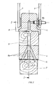
- Fig. 1 zeigt schematisch einen Schleifschuh, sowie ein zu schleifendes Profilstueck, teilweise in Ansicht und teilweise im Schnitt entlang der Linie I-I der Fig. 2.
- Fig. 2 zeigt den Schleifschuh im Schnitt entlang der Linie II-II der Fig. 1.
- Fig. 3 zeigt eine Ausfuehrungsform aehnlich der Fig. 1, jedoch unter Vorsehung aussenliegender Blasduesen, fuer die Erzeugung des Luftkissens zwischen dem Schleifschuh und dem Werkstueck;
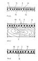
- Fig. 4 bis 6 zeigen in vergroessertem Massstab einen Schnitt durch das Schleifpapier, das mit dem zu schleifenden Profilstueck in Wirkverbindung steht, sowie mit den zwischen den Schleifkoernern gebildeten Luecken, die vollstaendig mit Schleifstaub angefuellt sind.
- Fig. 7 zeigt schematisch wie der Aufbau des Luftkissens zwischen dem Schleifpapier und dem zu schleifenden Profilstueck waehrend des Abhebens des Schleifschuhes vom Schleifstueck erfolgt.
- Fig. 8 zeigt schematisch den nach aussen gerichteten Ausstossvorgang des Luftkissens, sowie des Schleifstaubes waehrend der Rueckbewegung des Schleifschuhes in Richtung des zu schleifenden Profilstueckes.
- 1 schematically shows a grinding shoe and a profile piece to be ground, partly in view and partly in section along line II of FIG. 2.
- FIG. 2 shows the grinding shoe in a section along the line II-II of FIG. 1.
- FIG. 3 shows an embodiment similar to FIG. 1, but with the provision of external blow nozzles, for the generation of the air cushion between the grinding shoe and the workpiece;
- 4 to 6 show a section on an enlarged scale through the sandpaper, which is in operative connection with the profile piece to be sanded, as well as with the gaps formed between the sanding cores, which are completely filled with sanding dust.
- Fig. 7 shows schematically how the air cushion between the sandpaper and the profile piece to be sanded takes place during the lifting of the sanding shoe from the sanding piece.
- Fig. 8 shows schematically the outward ejection process of the air cushion and the grinding dust during the return movement of the grinding shoe in the direction of the profile piece to be ground.
Wie der Fig. 1 zu entnehmen ist, wird der Schleifschuh 1 in an sich bekannten Art und Weise z. B. von zwei Lenkern 2 und 3 aufgenommen, die unter Zuhilfenahme bekannter Antriebsvorrichtungen eine hin- und hergehende oder pendelnde Bewegung in Richtung des Pfeiles F durchfuehren. Ferner, unter Zuhilfenahme bekannter Steuernocken oder einer nicht dargestellten Zylinderkolbeneinheit,kann dem Schleifschuh 1 eine Hubbewegung oder eine Absenkbewegung in Richtung des Pfeiles G verliehen werden. An seiner Unterseite weist der Schleifschuh 1 in vorteilhafter Weise eine elastische Schicht 4 auf, auf der das Schleifpapier 5 angebracht ist. In der senkrecht zur Zeichnungsebene verlaufenden Richtung weist die untere Flaeche 6 des Schleifschuhes 1, auf der das Schleifpapier 5 beispielsweise aufgeklebt ist, ein Profil auf, das genau dem Profilstueck 7 entspricht, welches in Richtung des Pfeiles H bewegt wird. Im Inneren des Schleifschuhs 1, ist eine Leitung 8 vorgesehen, die mit einer nicht dargestellten Pressluftquelle in Verbindung steht.As can be seen from FIG. 1, the
Die Hauptleitung 8 fuer die Zufuhr der Pressluft, verzweigt sich in einzelne Nebenleitungen 8a, die in der Flaeche 6 aus dem Schleifhschuh 1 austreten. Das Schleifpapier 5 weist in Uebereinstimmung mit den Austrittsoeffnungen der Leitungen 8a geeignete Durchtrittsoeffnungen 9 auf. Diese Oeffnungen 9 sind derartig ueber die Flaeche 6 des Schleifschuhes 1 verteilt, dass stets ein Abdecken dieser Loecher durch die Flaeche des Profilstueckes 7 gewaehrleistet ist, um somit zwischen der zu schleifenden Flaeche und dem Schleifschuh 1 ein Luftkissen bilden zu koennen.The
Aus der Fig. 2 kann noch einmal die Anordnung der Druckluftzufuehrleitung 8, sowie des Anschi usstutzens 8b entnommen werden. Ferner koennen weitere Abzweigungen 8a vorgesehen werden. Im dargestellten Fall, muenden in die Oberflaeche 6 des Schleifschuhes 1 ueber Bohrungen 9 insgesamt neun Abzweigleitungen 8a.The arrangement of the compressed
In der Fig. 3 ist ein Schleifschuh 1 dargestellt, der im grossen und ganzen dem Schleifschuh gemaess Fig. 1 entspricht, lediglich mit dem Unterschied, dass fuer die Erzeugung des Luftkissens, zwischen der zu schleifenden Flaeche des Profilstueckes 7 und der unteren Flaeche 6 des Schleifschuhes 1, 4 keine Druckluftzufuehrkanaele 8, 8a im Inneren des Schleifschuhes 1 sowie keine entsprechenden Austrittsoeffnungen 9, die das Schleifpapier 5 durchdringen, vorgesehen sind.In Fig. 3, a
Zur Erzeugung des Luftkissens sind in diesem Falle Duesen 10 vorgesehen, die in der Naehe der unteren Kanten des Schleifschuhes 4 angeordnet sind. Diese Duesen 10 blasen bei angehobenem Schleifschuh 4 Druckluft zwischen die Oberflaeche des zu schleifenden Profilstueckes und die untere Flaeche 6 des Schleifschuhes 4, um somit zwischen Werkstueck und Schleifschuh das gewuenschte Luftkissen aufzubauen.In this case,
Die Zufuhr der Pressluft erfolgt kontinuierlich oder in genau gesteuerter Weise, in Abhaendigkeit von den Hubbewegungen des Schleifschuhes, unter Verwendung bekannter Steuerventile.The compressed air is supplied continuously or in a precisely controlled manner, depending on the lifting movements of the grinding shoe, using known control valves.
Das Prinzip, sowie die Arbeitsweise der Erfindung wird nun anhand der Zeichnungen 4 bis 8 genauer beschrieben.The principle and the mode of operation of the invention will now be described in more detail with reference to drawings 4 to 8.
Der Fig. 4 kann ein Stueck Schleifpapier im Schnitt entnommen werden. Von dem Papierstueck 5 stehen an der Unterseite Schleifkoerner 5a ab, die auf dem Papiertraeger unter Verwendung einer Leimschicht 5b fest angebracht sind. Zwischen den Schleifkoernern 5a sind Spanraeume gebildet, die mit 5c bezeichnet sind.The Fi g. 4 a piece of sandpaper can be removed in the cut. On the underside of the piece of
Der Fig. 5 kann entnommen werden, wie das Schleifpapier 5 arbeitet. Die Schleifkoerner 5a stehen in Beruehrung mit der Oberflaeche des Profilstueckes 7 und, entsprechend dem Schleifdruck P, werden durch die Spitzen der Schleifkoerner 5a, die Schneiden darstellen, vom Profilstueck 7 feine Spaene abgetragen, die sich in Form von Schleifstaub in den Spanraeumen 5c ablagern. Werden die Spanraeume 5c nicht rechtzeitig vom abgelagerten Schleifstaub befreit, so fuellen sich die Spanraeume 5c vollstaendig mit Schleifstaub an, wie dies mit 11 in Fig. 6 dargestellt ist. In diesem Falle, haben die Schneiden der Schleifkoener 5a keine Moeglichkeit mehr, vom Profilstueck 7 Material abzutragen, und ferner, tritt eine erhebliche Erhitzung des Schleifpapieres 5 ein, was ein Verdichten und Zusammenbacken des Schleifstaubes sowie der eingeschlossenen Harzpartikel mit sich bringt. Dies hat eine Zerstoerung des Schleifpapieres innerhalb weniger Minuten zur Folge.5 shows how the
Wie bereits vorher beschrieben, wurden bereits in der Vergangenheit Versuche unternommen, die vorgeschlagen haben, einen Luftstrom zwischen das Schleifpapier 5 und die Oberflaeche des Profilstueckes 7 einzublasen, es war jedoch nicht moeglich, zufriedenstellende Ergebnisse zu erzielen, da der eingeblasene Luftstrom nicht in der Lage war, aus den Spanraeumen 5c, zwischen den Schleifkoernern 5a, das abgetragene und verdichtete Schleifstaub zu entfernen.As previously described, attempts have been made in the past to propose an air flow between the
Diese unerwarteten und ueberraschenden Ergebnisse, lassen sich hingegen durch das erfindungsgemaesse Verfahren, wie dies anhand der Fig. 7 und 8 noch genauer beschrieben wird, erzielen.These unexpected and surprising results, on the other hand, can be achieved by the method according to the invention, as will be described in more detail with reference to FIGS. 7 and 8.
Durch kurzes Anheben des Schleifschuhes 1 in Richtung der Pfeiles G, um einen Betrag (a), der ungefaehr 0,1 bis 0,5 mm entspricht, wird zwischen der Flaeche des Profilstuckes 7 und dem Schleifpapier 5 eine seitlich offene Kammer 12 gebildet. Durch Einbringen von Druckluft in diese Kammer 12, ueber die Abzweigleitungen 8a sowie die Endbohrungen 9, wie dies schematisch durch die Flusslinien des Luftstromes angedeutet ist, baut sich in der Kammer 12 rasch ein mit 13 bezeichnetes Luftkissen auf.By briefly lifting the
Wird im Anschluss an den Aufbau des Luftkissens 13 der Schleifschuh 1 erneut in Richtung der Pfeiles G (Fig. 8) auf das Werkstueck zu bewegt, so wird das vorher aufgebaute Luftkissen 13 schlagartig und energisch nach aussen hin verdraengt.If, following the construction of the
Diese schlagartige Verdraengung des Luftkissens, fuehrt neben der Bildung erheblicher Luftwirbel im Luftstrom, zu einer sehr hohen Geschwindigkeit des Luftstromes in den Spanraeumen 5c , die zwischen den Schleifkoernern 5a gebildet sind. Der Luftstrom weist sehr hohe kinetische Energie auf, die dazu fuehrt, dass in entschiedener Weise von den Seitenwaenden Schleifkoerner 5a, sowie aus den Spanraeumen 5c, die Partikel und Staubkoerner des Schleifstaubes losgerissen und vom Luftstrom nach aussen gefoerdert werden, wie dies schematisch durch die Bezugszeichen 14 in der Fig. 8 dargestellt ist.This sudden displacement of the air cushion, in addition to the formation of considerable air vortices in the air flow, leads to a very high speed of the air flow in the
Der Aufbau des Luftkissens 13 in der Kammer 12 sowie die schlagartige und energische Verdraengung des Luftkissens in Richtung der Aussenseiten des Schleifschuhes 1, wiederholt sich zyklisch, z. B. jeweils nach 10 oder 20 hin- und hergehenden Schleifbewegungen (F) des Schleifschuhes 1, womit neben einer einwandfreien Kuehlung des Schleifpapieres 5 auch eine einwandfreie Abfuhr des Schleifstaubes gewaehrleistet wird. Waehrend bei herkoemmlichen Schleifschuhen dieser Art, die Standzeit des Schleifpapieres nur ueber wenige 100 m der zu schleifenden Profilstuecke anhielt, ist es unter Verwendung des erfindungsgemaessen Verfahrens, sowie der erfindungsgemaessen Vorrichtung nunmehr in ueberraschender Weise moeglich, ohne Unterbrechung mehrere 1000 m Profilstuecke zu schleifen und dies mit einem erheblichen Schleifdruck, wodurch nicht nur eine bessere Schleifqualitaet erzielbar ist, sondern die Produktivitaet dieser Schleifmaschinen erheblich gesteigert werden kann.The structure of the
Claims (9)
Applications Claiming Priority (2)
| Application Number | Priority Date | Filing Date | Title |
|---|---|---|---|
| IT2591380 | 1980-11-12 | ||
| IT25913/80A IT1134225B (en) | 1980-11-12 | 1980-11-12 | PROCEDURE AND MEANS TO RELEASE ABRASIVE PAPER FROM THE SANDING POWDER DEPOSITED |
Publications (2)
| Publication Number | Publication Date |
|---|---|
| EP0051720A2 true EP0051720A2 (en) | 1982-05-19 |
| EP0051720A3 EP0051720A3 (en) | 1983-04-20 |
Family
ID=11218126
Family Applications (1)
| Application Number | Title | Priority Date | Filing Date |
|---|---|---|---|
| EP81106619A Withdrawn EP0051720A3 (en) | 1980-11-12 | 1981-08-26 | Method and means for removing the grinding dust from a grinding belt |
Country Status (4)
| Country | Link |
|---|---|
| EP (1) | EP0051720A3 (en) |
| JP (1) | JPS57114364A (en) |
| ES (1) | ES8300036A1 (en) |
| IT (1) | IT1134225B (en) |
Cited By (2)
| Publication number | Priority date | Publication date | Assignee | Title |
|---|---|---|---|---|
| EP0412537A3 (en) * | 1989-08-11 | 1991-04-24 | Wacker-Chemitronic Gesellschaft Fuer Elektronik-Grundstoffe Mbh | Process and device for the treatment of chemico-mechanical publishing fabrics, particularly for semiconductor wafers |
| AU705780B2 (en) * | 1997-08-14 | 1999-06-03 | Asahi Kasei Kogyo Kabushiki Kaisha | Process and apparatus for treating development waste liquor |
Families Citing this family (1)
| Publication number | Priority date | Publication date | Assignee | Title |
|---|---|---|---|---|
| JP2643181B2 (en) * | 1987-09-24 | 1997-08-20 | トヨタ自動車株式会社 | Coolant supply method and apparatus in grinding |
Family Cites Families (5)
| Publication number | Priority date | Publication date | Assignee | Title |
|---|---|---|---|---|
| DE1099769B (en) * | 1961-02-16 | STRICO Gesellschaft für Metallurgie und Wärmetechnik m.b .H., Gummersbach (RhId.) | Bump blower | |
| US2646654A (en) * | 1950-03-17 | 1953-07-28 | Minnesota Mining & Mfg | Device for dressing coated abrasive belts |
| CH302508A (en) * | 1952-06-24 | 1954-10-31 | Eisenhut Jacob | Method and device for treating air-permeable objects, such as carpets and textiles, with an agent. |
| DE1037308B (en) * | 1957-01-11 | 1958-08-21 | Buetfering Maschfab Geb | Device for cleaning sanding belts |
| DE2402004A1 (en) * | 1974-01-11 | 1975-07-24 | Mach Bbs S A | Machine for dressing workpieces with opposing faces - has two grinding belts which between them advance opposing support mechanisms |
-
1980
- 1980-11-12 IT IT25913/80A patent/IT1134225B/en active
-
1981
- 1981-08-26 EP EP81106619A patent/EP0051720A3/en not_active Withdrawn
- 1981-11-10 JP JP56180252A patent/JPS57114364A/en active Pending
- 1981-11-11 ES ES507546A patent/ES8300036A1/en not_active Expired
Cited By (2)
| Publication number | Priority date | Publication date | Assignee | Title |
|---|---|---|---|---|
| EP0412537A3 (en) * | 1989-08-11 | 1991-04-24 | Wacker-Chemitronic Gesellschaft Fuer Elektronik-Grundstoffe Mbh | Process and device for the treatment of chemico-mechanical publishing fabrics, particularly for semiconductor wafers |
| AU705780B2 (en) * | 1997-08-14 | 1999-06-03 | Asahi Kasei Kogyo Kabushiki Kaisha | Process and apparatus for treating development waste liquor |
Also Published As
| Publication number | Publication date |
|---|---|
| ES507546A0 (en) | 1982-10-01 |
| EP0051720A3 (en) | 1983-04-20 |
| ES8300036A1 (en) | 1982-10-01 |
| IT8025913A0 (en) | 1980-11-12 |
| JPS57114364A (en) | 1982-07-16 |
| IT1134225B (en) | 1986-08-13 |
Similar Documents
| Publication | Publication Date | Title |
|---|---|---|
| DE69723992T2 (en) | METHOD AND DEVICE FOR A POWDER METALLURGICAL PROCESS | |
| DE3873791T2 (en) | MACHINE AND METHOD FOR GROUND PREPARATION. | |
| CH646628A5 (en) | GRINDING BODY FOR METAL WORKING. | |
| CH411325A (en) | Process and installation for the production of ground rubber from used rubber goods containing textile fibers | |
| EP1329288B1 (en) | Grinding for clothing | |
| EP0158200A2 (en) | Structured abrasive wheel | |
| DE102009053570B4 (en) | Cold press and process for the production of green compacts | |
| EP0865347B1 (en) | Device for smoothing panels or battens | |
| EP2785495B1 (en) | Grinding tool and method for producing same | |
| EP0051720A2 (en) | Method and means for removing the grinding dust from a grinding belt | |
| DE2931695C2 (en) | Abrasive tools for pre- and post-grinding | |
| DE3630189A1 (en) | ANTI-ADJUSTING DEVICE FOR GRINDING BODY | |
| DE69614945T2 (en) | Method and device for sharpening the surface of the grindstones of a wood grinder | |
| DE19804750A1 (en) | Polishing machine for manufacturing semiconductor chips | |
| DE2336350A1 (en) | AUTOMATIC GRINDING DEVICE CONTROL IN PULP PRODUCTION | |
| DE2851601C3 (en) | Method and device for producing wood pulp in a wood grinder | |
| WO1993002836A1 (en) | Method and apparatus for sharpening the surface of a grindstone in a pulp grinder | |
| EP0779391B1 (en) | Method for milling paper fibres | |
| DE10222956A1 (en) | Fine grinding machine comprises a tool support plate which rotates about an axis of rotation using a drive, a grinding strip pulled over the support surface of the support plate, a workpiece holder, and a pressing devices | |
| DE102008009507B4 (en) | Method and device for surface treatment of extremely hard materials | |
| DE102004007747B3 (en) | Grinding machine belt carrier has support layer with inside and outside, several spaced part support components being positioned on outside | |
| AT256447B (en) | Process for the production of ground rubber and spinnable textile threads from used rubber goods containing textile threads | |
| DE19921874A1 (en) | Device for surface grinding flatware | |
| EP3045054B1 (en) | Conveyor system for feeding a dense tobacco cake to a tobacco cutting device | |
| DE3314453A1 (en) | Method and device for profiling and/or trueing grinding wheels |
Legal Events
| Date | Code | Title | Description |
|---|---|---|---|
| PUAI | Public reference made under article 153(3) epc to a published international application that has entered the european phase |
Free format text: ORIGINAL CODE: 0009012 |
|
| AK | Designated contracting states |
Designated state(s): AT CH DE FR GB SE |
|
| PUAL | Search report despatched |
Free format text: ORIGINAL CODE: 0009013 |
|
| AK | Designated contracting states |
Designated state(s): AT CH DE FR GB LI SE |
|
| STAA | Information on the status of an ep patent application or granted ep patent |
Free format text: STATUS: THE APPLICATION IS DEEMED TO BE WITHDRAWN |
|
| 18D | Application deemed to be withdrawn |
Effective date: 19831221 |