EP0051720A2 - Procédé et moyen pour enlever les poussières de meulage d'une bande abrasive - Google Patents
Procédé et moyen pour enlever les poussières de meulage d'une bande abrasive Download PDFInfo
- Publication number
- EP0051720A2 EP0051720A2 EP81106619A EP81106619A EP0051720A2 EP 0051720 A2 EP0051720 A2 EP 0051720A2 EP 81106619 A EP81106619 A EP 81106619A EP 81106619 A EP81106619 A EP 81106619A EP 0051720 A2 EP0051720 A2 EP 0051720A2
- Authority
- EP
- European Patent Office
- Prior art keywords
- shoe
- grinding
- sanding
- profile piece
- grinding shoe
- Prior art date
- Legal status (The legal status is an assumption and is not a legal conclusion. Google has not performed a legal analysis and makes no representation as to the accuracy of the status listed.)
- Withdrawn
Links
Images



Classifications
-
- B—PERFORMING OPERATIONS; TRANSPORTING
- B24—GRINDING; POLISHING
- B24B—MACHINES, DEVICES, OR PROCESSES FOR GRINDING OR POLISHING; DRESSING OR CONDITIONING OF ABRADING SURFACES; FEEDING OF GRINDING, POLISHING, OR LAPPING AGENTS
- B24B53/00—Devices or means for dressing or conditioning abrasive surfaces
- B24B53/10—Devices or means for dressing or conditioning abrasive surfaces of travelling flexible backings coated with abrasives; Cleaning of abrasive belts
Definitions
- the above invention relates to a method and means for releasing an abrasive belt, which is mainly used in connection with a sleeping shoe which carries out a reciprocating or oscillating movement, from the grinding dust which has become lodged in the gaps between the abrasive cores.
- edge sanders. and / or profile grinding machines which are equipped with one or more grinding shoes, which execute a reciprocating or oscillating movement, on the side of the grinding shoe facing the profile piece, an abrasive paper is provided, whereby between the workpiece to be ground and the Abrasive paper develops a lot of heat during the sanding process, which leads to damage to the sandpaper.
- grinding dust settles very quickly between the grinding cores consists of wood dust, small wood shavings, small resin parts, paint particles or similar synthetic materials. This means that the sanding paper wears out quickly due to the sanding dust and resin deposits. These deposits very quickly form a layer that tends to cake, making the desired extraction of the grinding dust and resin particles impossible.
- profile grinding machines with a reciprocating or oscillating grinding shoe have so far not been able to establish themselves on the market, although these machines basically have considerable advantages, such as. B. the limited manufacturing costs of the machine, the better adaptability to complicated profile pieces, as well as the ability to cheaply and quickly produce the necessary sanding shoes that are used for the numerous different wooden profiles.
- the object of the above invention is to provide a method and a device with which it is possible to achieve the Avoid disadvantages inherent in the state of the art, and in particular excessive heating of the sandpaper and rapid wear of the sandpaper, due to caked-up deposits consisting of non-removed sanding dust and resin, and to ensure that the service life of the sandpaper is below the usually acceptable values decrease.
- the air cushion which has formed between the grinding shoe and the surface to be ground is displaced to the outside at high speed during the return movement of the grinding shoe in the direction of the workpiece to be ground.
- the result of this is that the air flow from the inside of the grinding shoe to its outside, with considerable energy content, with high pressure and very high speed.
- the above invention further relates to the means necessary to carry out the method.
- the means for carrying out the method are characterized in that the reciprocating sanding shoe is assigned a lifting device, and a compressed air source connected to lines and nozzles, which compressed air between the surface of the workpiece to be sanded and the lower surface consisting of sandpaper of the sanding pad.
- the lines for the supply of Compressed air is arranged inside the grinding shoe, in which several secondary lines branch off from a main feed line.
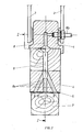
- the grinding shoe 1 is z. B. by two links 2 and 3, which perform a reciprocating or oscillating movement in the direction of arrow F with the aid of known drive devices. Furthermore, with the aid of known control cams or a cylinder piston unit (not shown), the grinding shoe 1 can be given a lifting movement or a lowering movement in the direction of the arrow G.
- the sanding shoe 1 advantageously has an elastic layer 4, on which the sanding paper 5 is attached.
- a line 8 is provided which is connected to a compressed air source, not shown.
- the main line 8 for the supply of compressed air branches into individual secondary lines 8a, which emerge from the grinding shoe 1 in the area 6.
- the sandpaper 5 has suitable passage openings 9. These openings 9 are distributed over the surface 6 of the grinding shoe 1 in such a way that these holes are always covered by the surface of the profile piece 7, so that an air cushion can be formed between the surface to be ground and the grinding shoe 1.
- a grinding shoe 1 which corresponds to the grinding shoe according to Fig. 1 on the whole, only with the difference that for the generation of the air cushion, between the surface of the profile piece 7 to be ground and the lower surface 6 of the Sanding shoe 1, 4 none Compressed air supply channels 8, 8a in the interior of the grinding shoe 1 and no corresponding outlet openings 9 which penetrate the sanding paper 5 are provided.
- nozzles 10 are provided to produce the air cushion, which are arranged near the lower edges of the grinding shoe 4. When the grinding shoe 4 is raised, these nozzles 10 blow compressed air between the surface of the profile piece to be ground and the lower surface 6 of the grinding shoe 4, in order to thus build up the desired air cushion between the workpiece and the grinding shoe.
- the compressed air is supplied continuously or in a precisely controlled manner, depending on the lifting movements of the grinding shoe, using known control valves.
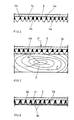
- the Fi g. 4 a piece of sandpaper can be removed in the cut.
- On the underside of the piece of paper 5 protrude abrasive grains 5a, which are firmly attached to the paper carrier using a glue layer 5b. Chip spaces, which are designated by 5c, are formed between the grinding cores 5a.
- the grinding grains 5a are in contact with the surface of the profile piece 7 and, according to the grinding pressure P, are touched by the tips of the grinding grains 5a, representing the cutting edges, 7 fine chips removed from the profile piece, which are deposited in the form of grinding dust in the chip spaces 5c. If the chip spaces 5c are not freed from the deposited grinding dust in good time, the chip spaces 5c are completely filled with grinding dust, as is shown at 11 in FIG. 6. In this case, the cutting edges of the abrasive grains 5a no longer have the possibility of removing material from the profile piece 7, and furthermore the abrasive paper 5 heats up considerably, which results in the grinding dust and the enclosed resin particles becoming compacted and caked together. This will destroy the sandpaper within a few minutes.
- a laterally open chamber 12 is formed between the surface of the profile piece 7 and the sanding paper 5.
- an air cushion, designated 13 quickly builds up in the chamber 12.
- the structure of the air cushion 13 in the chamber 12 and the abrupt and vigorous displacement of the air cushion in the direction of the outside of the grinding shoe 1, repeats itself cyclically, e.g. B. after every 10 or 20 reciprocating grinding movements (F) of the grinding shoe 1, which, in addition to a perfect cooling of the sanding paper 5, also ensures a perfect removal of the grinding dust.
Landscapes
- Engineering & Computer Science (AREA)
- Mechanical Engineering (AREA)
- Grinding-Machine Dressing And Accessory Apparatuses (AREA)
- Finish Polishing, Edge Sharpening, And Grinding By Specific Grinding Devices (AREA)
Applications Claiming Priority (2)
| Application Number | Priority Date | Filing Date | Title |
|---|---|---|---|
| IT2591380 | 1980-11-12 | ||
| IT25913/80A IT1134225B (it) | 1980-11-12 | 1980-11-12 | Procedimento e mezzi per liberare carta abrasiva dalla polvere di levigatura depositatasi |
Publications (2)
| Publication Number | Publication Date |
|---|---|
| EP0051720A2 true EP0051720A2 (fr) | 1982-05-19 |
| EP0051720A3 EP0051720A3 (fr) | 1983-04-20 |
Family
ID=11218126
Family Applications (1)
| Application Number | Title | Priority Date | Filing Date |
|---|---|---|---|
| EP81106619A Withdrawn EP0051720A3 (fr) | 1980-11-12 | 1981-08-26 | Procédé et moyen pour enlever les poussières de meulage d'une bande abrasive |
Country Status (4)
| Country | Link |
|---|---|
| EP (1) | EP0051720A3 (fr) |
| JP (1) | JPS57114364A (fr) |
| ES (1) | ES8300036A1 (fr) |
| IT (1) | IT1134225B (fr) |
Cited By (2)
| Publication number | Priority date | Publication date | Assignee | Title |
|---|---|---|---|---|
| EP0412537A3 (en) * | 1989-08-11 | 1991-04-24 | Wacker-Chemitronic Gesellschaft Fuer Elektronik-Grundstoffe Mbh | Process and device for the treatment of chemico-mechanical publishing fabrics, particularly for semiconductor wafers |
| AU705780B2 (en) * | 1997-08-14 | 1999-06-03 | Asahi Kasei Kogyo Kabushiki Kaisha | Process and apparatus for treating development waste liquor |
Families Citing this family (1)
| Publication number | Priority date | Publication date | Assignee | Title |
|---|---|---|---|---|
| JP2643181B2 (ja) * | 1987-09-24 | 1997-08-20 | トヨタ自動車株式会社 | 研削加工におけるクーラント供給方法および装置 |
Family Cites Families (5)
| Publication number | Priority date | Publication date | Assignee | Title |
|---|---|---|---|---|
| DE1099769B (de) * | 1961-02-16 | STRICO Gesellschaft für Metallurgie und Wärmetechnik m.b .H., Gummersbach (RhId.) | Stoßbläser | |
| US2646654A (en) * | 1950-03-17 | 1953-07-28 | Minnesota Mining & Mfg | Device for dressing coated abrasive belts |
| CH302508A (de) * | 1952-06-24 | 1954-10-31 | Eisenhut Jacob | Verfahren und Einrichtung zur Behandlung von luftdurchlässigen Gegenständen, wie Teppiche und Textilien, mit einem Mittel. |
| DE1037308B (de) * | 1957-01-11 | 1958-08-21 | Buetfering Maschfab Geb | Vorrichtung zum Reinigen von Schleifbaendern |
| DE2402004A1 (de) * | 1974-01-11 | 1975-07-24 | Mach Bbs S A | Maschine zum abrichten von werkstuecken mit zwei gegenueberliegenden oberflaechen |
-
1980
- 1980-11-12 IT IT25913/80A patent/IT1134225B/it active
-
1981
- 1981-08-26 EP EP81106619A patent/EP0051720A3/fr not_active Withdrawn
- 1981-11-10 JP JP56180252A patent/JPS57114364A/ja active Pending
- 1981-11-11 ES ES507546A patent/ES8300036A1/es not_active Expired
Cited By (2)
| Publication number | Priority date | Publication date | Assignee | Title |
|---|---|---|---|---|
| EP0412537A3 (en) * | 1989-08-11 | 1991-04-24 | Wacker-Chemitronic Gesellschaft Fuer Elektronik-Grundstoffe Mbh | Process and device for the treatment of chemico-mechanical publishing fabrics, particularly for semiconductor wafers |
| AU705780B2 (en) * | 1997-08-14 | 1999-06-03 | Asahi Kasei Kogyo Kabushiki Kaisha | Process and apparatus for treating development waste liquor |
Also Published As
| Publication number | Publication date |
|---|---|
| EP0051720A3 (fr) | 1983-04-20 |
| ES507546A0 (es) | 1982-10-01 |
| ES8300036A1 (es) | 1982-10-01 |
| IT1134225B (it) | 1986-08-13 |
| JPS57114364A (en) | 1982-07-16 |
| IT8025913A0 (it) | 1980-11-12 |
Similar Documents
| Publication | Publication Date | Title |
|---|---|---|
| DE69723992T2 (de) | Verfahren und gerät für einen pulvermetallurgischen prozess | |
| DE3873791T2 (de) | Maschine und methode zur bodenvorbereitung. | |
| CH646628A5 (de) | Schleifkoerper fuer die metallbearbeitung. | |
| CH411325A (de) | Verfahren und Anlage zum Herstellen von gemahlenem Kautschuk aus gebrauchten textilfaserhaltigen Kautschukwaren | |
| EP1329288B1 (fr) | Meulage de garnitures | |
| EP0158200A2 (fr) | Meule profilée | |
| DE102009053570B4 (de) | Kaltpresse und Verfahren zur Herstellung von Grünlingen | |
| EP0865347B1 (fr) | Dispositif pour lisser des plaques et baguettes | |
| EP0779647A1 (fr) | Méthode et appareil pour le traitement de matériaux semi-conducteurs | |
| EP2785495B1 (fr) | Outil de rectification et son procédé deproduction | |
| DE2931695C2 (de) | Schleifkörper zum Vor- und Nachschleifen | |
| DE3630189A1 (de) | Antizusetzvorrichtung fuer schleifkoerper | |
| DE69614945T2 (de) | Verfahren und Vorrichtung zum Schärfen der Oberfläche der Schleifsteine eines Holzschleifers | |
| DE19804750A1 (de) | Poliervorrichtung | |
| DE2336350A1 (de) | Automatische schleifvorrichtungssteuerung bei der pulpenherstellung | |
| DE2851601C3 (de) | Verfahren und Einrichtung zur Herstellung von Holzschliff in einem Holzschleifer | |
| WO1993002836A1 (fr) | Procede et appareil permettant d'affuter la surface d'une meule de defibreur | |
| EP0779391B1 (fr) | Procédé pour le broyage de fibres de papier | |
| DE10222956A1 (de) | Feinschleifmaschine | |
| DE102008009507B4 (de) | Verfahren und Vorrichtung zur Oberflächenbearbeitung extrem harter Werkstoffe | |
| DE102004007747B3 (de) | Schleifbandträger und Schleifbandanordnung | |
| AT256447B (de) | Verfahren zum Herstellen von gemahlenem Kautschuk und von spinnbaren Textilfäden aus gebrauchten, textilfadenhaltigen Kautschukwaren | |
| DE19921874A1 (de) | Vorrichtung zum Oberflächenschleifen von Flachgeschirr | |
| EP3045054B1 (fr) | Dispositif de transport d'une balle de tabac comprimée au dispositif de découpe de tabac | |
| DE3314453A1 (de) | Verfahren und vorrichtung zum profilieren und/oder abrichten von schleifkoerpern |
Legal Events
| Date | Code | Title | Description |
|---|---|---|---|
| PUAI | Public reference made under article 153(3) epc to a published international application that has entered the european phase |
Free format text: ORIGINAL CODE: 0009012 |
|
| AK | Designated contracting states |
Designated state(s): AT CH DE FR GB SE |
|
| PUAL | Search report despatched |
Free format text: ORIGINAL CODE: 0009013 |
|
| AK | Designated contracting states |
Designated state(s): AT CH DE FR GB LI SE |
|
| STAA | Information on the status of an ep patent application or granted ep patent |
Free format text: STATUS: THE APPLICATION IS DEEMED TO BE WITHDRAWN |
|
| 18D | Application deemed to be withdrawn |
Effective date: 19831221 |