EP0051772B1 - Bedienungshebel mit Sicherheitseinrichtung für Steuerventile mit handbetätigtem gleitenden Verteiler, angewandt in hydraulisch betätigten Hebetriebwerken und Förderaggregaten - Google Patents
Bedienungshebel mit Sicherheitseinrichtung für Steuerventile mit handbetätigtem gleitenden Verteiler, angewandt in hydraulisch betätigten Hebetriebwerken und Förderaggregaten Download PDFInfo
- Publication number
- EP0051772B1 EP0051772B1 EP81108758A EP81108758A EP0051772B1 EP 0051772 B1 EP0051772 B1 EP 0051772B1 EP 81108758 A EP81108758 A EP 81108758A EP 81108758 A EP81108758 A EP 81108758A EP 0051772 B1 EP0051772 B1 EP 0051772B1
- Authority
- EP
- European Patent Office
- Prior art keywords
- pivot
- lever
- yoke
- operated
- manually
- Prior art date
- Legal status (The legal status is an assumption and is not a legal conclusion. Google has not performed a legal analysis and makes no representation as to the accuracy of the status listed.)
- Expired
Links
Images


Classifications
-
- F—MECHANICAL ENGINEERING; LIGHTING; HEATING; WEAPONS; BLASTING
- F16—ENGINEERING ELEMENTS AND UNITS; GENERAL MEASURES FOR PRODUCING AND MAINTAINING EFFECTIVE FUNCTIONING OF MACHINES OR INSTALLATIONS; THERMAL INSULATION IN GENERAL
- F16H—GEARING
- F16H61/00—Control functions within control units of change-speed- or reversing-gearings for conveying rotary motion ; Control of exclusively fluid gearing, friction gearing, gearings with endless flexible members or other particular types of gearing
- F16H61/18—Preventing unintentional or unsafe shift, e.g. preventing manual shift from highest gear to reverse gear
-
- G—PHYSICS
- G05—CONTROLLING; REGULATING
- G05G—CONTROL DEVICES OR SYSTEMS INSOFAR AS CHARACTERISED BY MECHANICAL FEATURES ONLY
- G05G5/00—Means for preventing, limiting or returning the movements of parts of a control mechanism, e.g. locking controlling member
- G05G5/02—Means preventing undesired movements of a controlling member which can be moved in two or more separate steps or ways, e.g. restricting to a stepwise movement or to a particular sequence of movements
Definitions
- the invention relates to an operating lever, incorporating a safety device, for control valves of manually-operated sliding-spool type used in hydraulically-operated lifting gears and conveyor systems i.e.: a stick on which to lay hold and by means of which manipulate the control valve which operates machinery, or parts thereof, employed in the lifting of loads or the moving about of materials by internal industrial conveyor plants: the inclusion of the safety device in the lever assembly being intended more especially to prevent against untimely function of machinery arising from unwarranted operations by unskilled personnel.
- the aforesaid technology is susceptible to further improvement with regard to the fact that a simple shield affords insufficient protection in itself against the possibility of the lever's being manipulated by a child, or other inexpert individual, occasioning unwanted operation of machinery or parts thereof and consequent risk of serious danger to persons and property.
- Said operating lever 24 is further pulled into said locked safety position by said compression spring 28 which is resting upon said pivotably mounted body 15.
- Said lever 24 is further solidarly jointed with a locking rod 26 which, in the locked situation, penetrates and engages a locking aperture 23.
- Said lever 24 is further provided with a locking pin which, according to said first (axial) and second (rotational) movements of said lever 24, cooperates with a locking groove 32 and with an unlocking groove 33 respectively.
- said lever In order to replace said lever 24 on said safety locked position, said lever has to be moved first axially and manually, against the force exerted by said compression spring 28, towards said pivotably mounted body 15 until its locking rod 26 engages again said locking aperture 23 and then rotated in the direction opposite to that which has provoked the unlocking of said lever 24.
- the reference numbers are that of said DE-A--2611 628).
- a manually controlled actuating device including a shaft ad- justably mounted for movement from a predetermined rest-position whereby means comprising a compression spring surrounding a rod which shows a locking pin are provided to ensure the locking of said shaft at said rest-position and to ensure that said shaft comes in any case back to said rest-position when no more force is manually applied to a suitably conformed handle mounted on said shaft. From the above outline one may discern the necessity for a solution to the technical problem posed by a lever incapable of operation by a child or other inexpert individual i.e.: a lever corresponding to recently prescribed accident prevention standards.
- an operating lever with safety device for control valves of manually-operated sliding spool type used in hydraulically operated lifting-gears and conveying-plants, comprising a manually operated lever connected to a yoke, said yoke being arranged to rotate around a first transversally placed pivot supported by a bracket extending from a supporting plate attached to the control valve body wherein a piston is caused to stroke, the shank of said piston being furnished with a hole accommodating a second pivot having prismatic extremities which engage two slots provided in said yoke, characterised by the fact that said lever is fixedly connected to a third pivot, said third pivot being rotatably accommodated within a bush, said bush being in turn fixedly connected with said yoke; the extremity of said third pivot other than that lodged within said bush having fixed there to a radial arm furnished with a lateral tooth adopted for insertion into a slot located in a protruding portion of said bracket which forms
- the advantage provided by the invention is that of having provided a simple and effective safety device which will prevent the lever from being moved in the traditional direction of operation, in the event of its being laid hold on by a child or other inexpert individual.
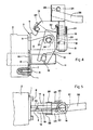
- 1 denotes a supporting plate connecting a fixture 3 to the valve body 2, fixture 3 is furnished with a bracket 4 which form integral part thereof and extends into a further protruding portion 5 provided with a slot denoted by 6; 7 denotes holes located in said supporting plate 1 for fixing said plate to valve body 2 by means of insertion of fastening screwed bolts 8; 9 denotes an aperture in supporting plate 1 through which the piston 10 of control valve 2 is destined to pass; 11 denotes the shank of piston 10, furnished with a through hole 30 (Fig. 2) to accommodate a pivot 29 (Fig.
- a tooth 20 is affixed, this being disposed laterally thereon and designed to seek out and mate with slot 6 in bracket portion 5 thus establishing the locked, or safe position;
- 21 denotes a torsion spring surrounding said pivot 16, the extremities 22 & 23 of said spring 21 engage respectively with that face of radial arm 19 other than the face bearing said tooth 20, and with the rearward edge of yoke appendage 14;
- 24 denotes a cramp affixed to the uppermost extremity of pivot 16 furnished with a screwed clamping bolt 25 for holding fast the extremity of the operating lever 26, the latter being provided with an handgrip, or knob 27;
- 28 denotes a transversally placed pivot providing a rotational articulation between fixture 3 and bracket 4;
- the invention functions in the following manner: from the locked position (Fig. 1) the operator causes the device to pass into one of the working positions (Fig. 2) by manipulating lever 26 so as to produce its rotation around pivot 16 against the force exerted by torsion spring 21, thus occasioning lateral disengagement of tooth 20 from slot 6 in bracket portion 5; this accomplished, the operator then acts on lever 26, causing its rotation around transversal pivot 28 in the normal fashion thus making piston 10 to stroke in one direction or the other in order to provoke the flow of hydraulic fluid through the body of chamber 2.
- Angular displacements of lever 26 in the traditional directions produce corresponding angular movements of radial arm 19 and yoke 14, which in turn cause related movements between shank 11, pivot extremities 12 and slots 13, and ultimately rotations of pivot 29.
Landscapes
- Engineering & Computer Science (AREA)
- General Engineering & Computer Science (AREA)
- Physics & Mathematics (AREA)
- General Physics & Mathematics (AREA)
- Automation & Control Theory (AREA)
- Mechanical Engineering (AREA)
- Mechanically-Actuated Valves (AREA)
- Mechanical Control Devices (AREA)
Claims (1)
- Bedienungshebel mit Sicherheitseinrichtung für Steuerventile mit handbetätigtem gleitenden Verteiler, angewandt in hydraulisch betätigten Hebetriebwerken und Förderaggregaten, der einen handbetätigten mit einem Joch (14) verbundenen Hebel (26) aufweist, wobei das Joch zur Drehung um einen ersten querliegenden und durch eine Gabel (4) gestützten Stift (28) ausgebildet ist, die Gabel von einer am Steuerventilgehäuse (2) befestigten Halteplatte (1) vorsteht, worin eine Kolben (10) seinen Hub ausführt, der Kolbensshaft (11) mit einer Bohrung (30) zur Aufnahme eines zweiten Stiftes (29) mit prismenförmigen Enden versehen ist, die in die beiden Schlitze (13) genannten Jochs eingreifen, dadurch gekennzeichnet, dass der genannte Hebel (26) mit einem dritten Stift (16) fest verbunden ist, wobei dieser dritte Stift (16) drehend in einer Buchse (15) gelagert ist und die Buchse (15) fest mit genanntem Joch (14) verbunden ist; das Ende des dritten Stiftes (16), das nicht in genannter Buchse (15) gelagert ist, hat einen Radialarm (19) mit einem Seitenzahn (20) zum Eingreifen in den Schlitz (6) auf dem vorstehenden Abschnitt (5) genannter Gabel (4) daran befestigt, sodass die Gabel einen Bestandteil dieser Befestigung (3) bildet und somit eine geschlossene Sicherheitsposition darstellt; diese Befestigung (3) ist das Mittel, durch welches der genannte erste querliegende Stift (28) auf genannter Halteplatte (1) aufliegt und dadurch auch auf dem Gehäuse (2) des vorgenannten Steuerventils; eine Torsionsfeder (21) um genannten dritten Stift (16) gelagert, um welchen genannter Hebel (26) dreht, ist mit ihren Enden auf der einen Seite gegen den genannten Radialarm (19) verankert, aur der anderen Seitegegen einen Anhang von genanntem Joch (14) ausgehend.
Applications Claiming Priority (2)
| Application Number | Priority Date | Filing Date | Title |
|---|---|---|---|
| ITMO1980U29050U IT8029050U1 (it) | 1980-11-12 | 1980-11-12 | Leva di azionamento del distributore oleoidraulico a cassetto con dispositivo di sicurezza, nelle macchine per sollevamento e per trasporti interni |
| IT2905080U | 1980-11-12 |
Publications (3)
| Publication Number | Publication Date |
|---|---|
| EP0051772A2 EP0051772A2 (de) | 1982-05-19 |
| EP0051772A3 EP0051772A3 (en) | 1983-04-27 |
| EP0051772B1 true EP0051772B1 (de) | 1986-07-23 |
Family
ID=11225978
Family Applications (1)
| Application Number | Title | Priority Date | Filing Date |
|---|---|---|---|
| EP81108758A Expired EP0051772B1 (de) | 1980-11-12 | 1981-10-22 | Bedienungshebel mit Sicherheitseinrichtung für Steuerventile mit handbetätigtem gleitenden Verteiler, angewandt in hydraulisch betätigten Hebetriebwerken und Förderaggregaten |
Country Status (3)
| Country | Link |
|---|---|
| EP (1) | EP0051772B1 (de) |
| DE (1) | DE3174985D1 (de) |
| IT (1) | IT8029050U1 (de) |
Families Citing this family (1)
| Publication number | Priority date | Publication date | Assignee | Title |
|---|---|---|---|---|
| DE3327923A1 (de) * | 1983-08-03 | 1985-02-21 | Ideal-Standard Gmbh, 5300 Bonn | Sanitaeres einhebel-wasserventil |
Family Cites Families (4)
| Publication number | Priority date | Publication date | Assignee | Title |
|---|---|---|---|---|
| US2512312A (en) * | 1948-04-05 | 1950-06-20 | Bendix Aviat Corp | Lever handle detent and release |
| GB949250A (en) * | 1961-09-29 | 1964-02-12 | Short Brothers & Harland Ltd | Improved locking means for a pivoted selector lever |
| DE2611628A1 (de) * | 1976-03-19 | 1977-09-22 | Bosch Gmbh Robert | Betaetigungseinrichtung fuer wegeventile |
| US4229993A (en) * | 1978-04-07 | 1980-10-28 | Andresen Herman J | Actuating device |
-
1980
- 1980-11-12 IT ITMO1980U29050U patent/IT8029050U1/it unknown
-
1981
- 1981-10-22 DE DE8181108758T patent/DE3174985D1/de not_active Expired
- 1981-10-22 EP EP81108758A patent/EP0051772B1/de not_active Expired
Also Published As
| Publication number | Publication date |
|---|---|
| IT8029050U1 (it) | 1982-05-12 |
| DE3174985D1 (en) | 1986-08-28 |
| EP0051772A3 (en) | 1983-04-27 |
| EP0051772A2 (de) | 1982-05-19 |
| IT8029050V0 (it) | 1980-11-12 |
Similar Documents
| Publication | Publication Date | Title |
|---|---|---|
| CA2218963C (en) | Electrically driven actuator with failsafe feature | |
| US5477752A (en) | Valve actuator declutch mechanism | |
| US6301864B1 (en) | Interlock for lawnmower | |
| EP0133981B1 (de) | Mechanische Überlastungssicherung | |
| CA1052299A (en) | Device for discontinuing and automatically restoring the operational function of a spring brake actuator | |
| EP4019384B1 (de) | Aktuatorvorrichtung für eine fahrradgangschaltung und entsprechende fahrradgangschaltung | |
| US5584378A (en) | Safety switch assembly | |
| JPH08178119A (ja) | ばね復帰アクチュエータ | |
| GB1582973A (en) | Buckle for a multiple array of safety belt elements | |
| EP0894712A2 (de) | Hubschrauber-Rotorbremse | |
| AU6391301A (en) | Actuating device | |
| KR0165960B1 (ko) | 로더용 페달록킹장치 | |
| EP3073155B1 (de) | Vorrichtung zur hemmung der auswahl einer oder mehrerer betriebspositionen eines auswahlelements eines automatisch betätigten getriebes, zum beispiel eine parkstellung | |
| EP0628741B1 (de) | Fahrzeug-Kupplungsbaugruppe, insbesondere für Traktoren | |
| EP0051772B1 (de) | Bedienungshebel mit Sicherheitseinrichtung für Steuerventile mit handbetätigtem gleitenden Verteiler, angewandt in hydraulisch betätigten Hebetriebwerken und Förderaggregaten | |
| US4636221A (en) | Elbow lock mechanism | |
| EP0090540B1 (de) | Druckmittelzylinder mit Verriegelungsstellungsanzeiger | |
| JPH11503705A (ja) | 支柱持上げ式フレーム | |
| US4126057A (en) | Adjustable length upper guide member | |
| EP3536862A1 (de) | Schnellverschluss | |
| EP1931900B1 (de) | Betätigungsvorrichtung | |
| KR20090129491A (ko) | 기어 변속 시스템 | |
| US4865269A (en) | Overtravel stop and neutral position lock | |
| US3967709A (en) | Interlock system for parking brake and transmission control | |
| EP1252807B1 (de) | Kuppelgestell für landwirtschaftliche Maschine |
Legal Events
| Date | Code | Title | Description |
|---|---|---|---|
| PUAI | Public reference made under article 153(3) epc to a published international application that has entered the european phase |
Free format text: ORIGINAL CODE: 0009012 |
|
| AK | Designated contracting states |
Designated state(s): DE FR GB |
|
| PUAL | Search report despatched |
Free format text: ORIGINAL CODE: 0009013 |
|
| 17P | Request for examination filed |
Effective date: 19821227 |
|
| AK | Designated contracting states |
Designated state(s): DE FR GB |
|
| GRAA | (expected) grant |
Free format text: ORIGINAL CODE: 0009210 |
|
| AK | Designated contracting states |
Kind code of ref document: B1 Designated state(s): DE FR GB |
|
| REF | Corresponds to: |
Ref document number: 3174985 Country of ref document: DE Date of ref document: 19860828 |
|
| ET | Fr: translation filed | ||
| PLBE | No opposition filed within time limit |
Free format text: ORIGINAL CODE: 0009261 |
|
| STAA | Information on the status of an ep patent application or granted ep patent |
Free format text: STATUS: NO OPPOSITION FILED WITHIN TIME LIMIT |
|
| 26N | No opposition filed | ||
| PGFP | Annual fee paid to national office [announced via postgrant information from national office to epo] |
Ref country code: GB Payment date: 19900907 Year of fee payment: 10 |
|
| PGFP | Annual fee paid to national office [announced via postgrant information from national office to epo] |
Ref country code: FR Payment date: 19901022 Year of fee payment: 10 |
|
| PGFP | Annual fee paid to national office [announced via postgrant information from national office to epo] |
Ref country code: DE Payment date: 19901229 Year of fee payment: 10 |
|
| PG25 | Lapsed in a contracting state [announced via postgrant information from national office to epo] |
Ref country code: GB Effective date: 19911022 |
|
| GBPC | Gb: european patent ceased through non-payment of renewal fee | ||
| PG25 | Lapsed in a contracting state [announced via postgrant information from national office to epo] |
Ref country code: FR Effective date: 19920630 |
|
| PG25 | Lapsed in a contracting state [announced via postgrant information from national office to epo] |
Ref country code: DE Effective date: 19920701 |
|
| REG | Reference to a national code |
Ref country code: FR Ref legal event code: ST |