EP3536862A1 - Schnellverschluss - Google Patents
Schnellverschluss Download PDFInfo
- Publication number
- EP3536862A1 EP3536862A1 EP19161403.1A EP19161403A EP3536862A1 EP 3536862 A1 EP3536862 A1 EP 3536862A1 EP 19161403 A EP19161403 A EP 19161403A EP 3536862 A1 EP3536862 A1 EP 3536862A1
- Authority
- EP
- European Patent Office
- Prior art keywords
- tappet
- seat
- coupling according
- coupling
- pin
- Prior art date
- Legal status (The legal status is an assumption and is not a legal conclusion. Google has not performed a legal analysis and makes no representation as to the accuracy of the status listed.)
- Granted
Links
Images

Classifications
-
- E—FIXED CONSTRUCTIONS
- E02—HYDRAULIC ENGINEERING; FOUNDATIONS; SOIL SHIFTING
- E02F—DREDGING; SOIL-SHIFTING
- E02F3/00—Dredgers; Soil-shifting machines
- E02F3/04—Dredgers; Soil-shifting machines mechanically-driven
- E02F3/28—Dredgers; Soil-shifting machines mechanically-driven with digging tools mounted on a dipper- or bucket-arm, i.e. there is either one arm or a pair of arms, e.g. dippers, buckets
- E02F3/36—Component parts
- E02F3/3604—Devices to connect tools to arms, booms or the like
- E02F3/3609—Devices to connect tools to arms, booms or the like of the quick acting type, e.g. controlled from the operator seat
- E02F3/3627—Devices to connect tools to arms, booms or the like of the quick acting type, e.g. controlled from the operator seat with a hook and a longitudinal locking element
-
- E—FIXED CONSTRUCTIONS
- E02—HYDRAULIC ENGINEERING; FOUNDATIONS; SOIL SHIFTING
- E02F—DREDGING; SOIL-SHIFTING
- E02F3/00—Dredgers; Soil-shifting machines
- E02F3/04—Dredgers; Soil-shifting machines mechanically-driven
- E02F3/28—Dredgers; Soil-shifting machines mechanically-driven with digging tools mounted on a dipper- or bucket-arm, i.e. there is either one arm or a pair of arms, e.g. dippers, buckets
- E02F3/36—Component parts
- E02F3/3604—Devices to connect tools to arms, booms or the like
- E02F3/3609—Devices to connect tools to arms, booms or the like of the quick acting type, e.g. controlled from the operator seat
- E02F3/3622—Devices to connect tools to arms, booms or the like of the quick acting type, e.g. controlled from the operator seat with a hook and a locking element acting on a pin
-
- E—FIXED CONSTRUCTIONS
- E02—HYDRAULIC ENGINEERING; FOUNDATIONS; SOIL SHIFTING
- E02F—DREDGING; SOIL-SHIFTING
- E02F3/00—Dredgers; Soil-shifting machines
- E02F3/04—Dredgers; Soil-shifting machines mechanically-driven
- E02F3/28—Dredgers; Soil-shifting machines mechanically-driven with digging tools mounted on a dipper- or bucket-arm, i.e. there is either one arm or a pair of arms, e.g. dippers, buckets
- E02F3/36—Component parts
- E02F3/3604—Devices to connect tools to arms, booms or the like
- E02F3/3609—Devices to connect tools to arms, booms or the like of the quick acting type, e.g. controlled from the operator seat
- E02F3/3663—Devices to connect tools to arms, booms or the like of the quick acting type, e.g. controlled from the operator seat hydraulically-operated
-
- E—FIXED CONSTRUCTIONS
- E02—HYDRAULIC ENGINEERING; FOUNDATIONS; SOIL SHIFTING
- E02F—DREDGING; SOIL-SHIFTING
- E02F9/00—Component parts of dredgers or soil-shifting machines, not restricted to one of the kinds covered by groups E02F3/00 - E02F7/00
- E02F9/26—Indicating devices
Definitions
- the present invention concerns a quick coupling for coupling tools through the interposition of a respective adapter provided with two coupling axes.
- the present invention refers to a quick coupling for coupling tools through the interposition of a respective adapter provided with two coupling axes, the quick coupling being provided with its own actuating device.
- the present invention refers to a quick coupling for coupling tools through the interposition of a respective adapter provided with two coupling axes, the quick coupling being provided with its own actuating device and a mechanical type safety device suitable to prevent accidental detachment of the adapter.
- Said interfaces comprise an adapter member provided in the majority of cases with two parallel axes positioned at a given distance to be compatible with a quick coupling, which consists of an equipment provided with mechanisms arranged to selectively couple with the two axes of the adapter member.
- a quick coupling which consists of an equipment provided with mechanisms arranged to selectively couple with the two axes of the adapter member.
- the manufacturers of quick couplings provide adapter members appropriately designed to couple with their own quick couplings to make the tools interfaceable with their own quick couplings.
- the quick couplings normally comprising a box-shaped frame which delimits a chamber arranged to house an operating assembly and locking members.
- the frame has a pair of sides connected to each other by a base plate and comprises a cover which closes the chamber at the top and is connected to the sides in a detachable manner.
- the sides are symmetrically shaped, and each of them develops longitudinally between a respective fork portion and a coupling portion, each of said portions being shaped to house any one of the axles.
- the frame comprises a further plate which has a pair of service holes for a longitudinal locking pin.
- the locking pins are located alongside each other and carried by a transverse connection member which can be longitudinally operated by a linear actuator, either of a mechanical or fluid-dynamic type.
- the actuator is adapted to move the connection member, and therefore the pins, between an operatively neutral retracted position and a forward position in which the heads of the pins cooperate with the coupling portions of the two sides to provide a housing for one of the axles of the adapter.
- the European patent no. EP 2824243 of the applicant describes a quick coupling for an adapter with two axes installable on a mechanical arm of an operating machine.
- Said actuator comprises a safety device provided with a further hydraulically operated linear actuator, the function of which is to move a further locking pin, the purpose of which is to interact, in use, with the upper portion of the axle which engages the sides of the adapter on the side of the fork portions in order to lock the axle contained by the latter.
- a safety device provided with a further hydraulically operated linear actuator, the function of which is to move a further locking pin, the purpose of which is to interact, in use, with the upper portion of the axle which engages the sides of the adapter on the side of the fork portions in order to lock the axle contained by the latter.
- operation of the further linear actuator is functionally independent of operation of the longitudinal locking pins.
- a quick coupling which comprises a safety device that can be mechanically operated and is arranged to come into operation controlled by the device that operates the longitudinal locking pins, after the first axle of the adapter has been loaded by the quick coupling, highlighting the impossibility of perfecting the coupling with the second axle. Said problem is currently unresolved and represents an interesting challenge for the applicant.
- the present invention relates to a quick coupling for coupling tools through the interposition of a respective adapter provided with two coupling axes.
- the present invention refers to a quick coupling for coupling tools through the interposition of a respective adapter provided with two coupling axes, the quick coupling being provided with its own actuating device.
- the present invention refers to a quick coupling for coupling tools through the interposition of a respective adapter provided with two coupling axes, the quick coupling being provided with its own actuating device and a mechanical type safety device suitable to prevent accidental detachment of the adapter.
- a quick coupling for an adapter for tools provided with two axles; said coupling comprising a box-shaped frame provided with a pair of sides extending along a given direction, each of which is delimited at the front by an abutment for said axles; a locking assembly being arranged between said sides and comprising a pair of first pins parallel to said direction and integrally coupled by a connection member; each said side ending at the back in a respective hook provided with a seat for said axles; an actuating device being provided to move them with reciprocating motion in said direction between a first retracted position and an operative position facing said abutment; characterized in that said assembly comprises a safety device suitable to lock a said axle by mechanical interference and mechanically operated by said connection member.
- said safety device comprises a tappet carried in a rotatable manner by said frame from and towards an engagement position of said seat and has a head portion shaped to be arranged at a substantially diametral distance from said hook.
- said tappet is carried in a rotatable manner by said frame around a second pin transverse to said direction; said safety device comprising a cam integral with said connection member and mechanically coupled with said tappet by means of a respective third pivot pin parallel to said second pin to move said tappet alternately from said engagement position to a said disengagement position of said seat in which said tappet is positioned over said connection member.
- said cam has a slot engaged by said third pin to couple said tappet to said cam bilaterally; said tappet having a curved portion concentric to said axis angularly delimited by said head portion.
- said tappet comprises a crank opposite said head portion and a connecting rod pivoted about said connection member by means of a pin.
- the quick coupling comprises signalling means suitable to indicate whether said tappet is in said engagement position of said seat or in said disengagement position.
- said signalling assembly is of the visual type.
- said safety device is provided with a signalling assembly for signalling an operative condition of said safety device visible at the back.
- said signalling assembly may be associated with a covering element carried integrally by said frame above said assembly; said signalling means comprising a pair of signs in contrasting colours provided in the covering element.
- a first sign of said pair of signs is located in said covering element facing said seat so as to be covered by said head portion when, in use, said tappet is in said engagement position of said seat; a second sign of said pair of signs being located beside said first sign so as to be covered by said head portion when, in use, said tappet is arranged in said disengagement position of said seat.
- said first sign is circular-shaped and red; said second sign being circular-shaped and green.
- said head portion projects radially from said curved surface.
- each said first pin has a duckbill-shaped free end on the side of said abutments to selectively define a housing for said axles together with said abutments.
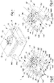
- the number 1 indicates overall a quick coupling 1 for an adapter A for tools, generally but not limited to an excavation tool.
- Said adapter A is normally used to equip a mechanical arm, known and not illustrated for the sake of economy of drawing, of an operating machine and, in the case illustrated in the attached figures, is of the type provided with two parallel axles AX1 and AX2 arranged transversally to a longitudinal direction D for the set composed of coupling 1 and adapter A.
- the coupling 1 comprises a box-shaped frame 10 provided with a cover 5, a pair of parallel sides 16 and 16', which extend along the direction D, each of which ends at the front in an abutment 12/12' for the axles AX1 and AX2 and at the back in a hook 140/140' .
- the set of the two abutments 12 and 12' defines a front supporting portion for the axles AX1 and AX2, at respective edge portions, and the set of the two hooks 140 and 140' defines at the back a seat 14 for the axles AX1 and AX2.
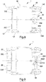
- each hook 140/140' has two adjacent concave portions 142 and 144 ( figures 5 and 7 ), each of which is delimited by a cylindrical surface 1420 and 1440, the outermost one of which has a width smaller than 135°, to act as a lead and first support for the axles AX1 and AX2, and the innermost one of which has a width that approximates 240°, to axially centre the position of said axles AX1 and AX2 relative to the coupling 1.
- the two sides 16 and 16' laterally limit a chamber 100 which is longitudinally delimited by a first front wall 101 arranged transversally to the direction D and at the back by a second rear wall 102, substantially parallel to the first wall 101, which delimits at the front the seat 14.
- the frame 10 carries a locking assembly 20 inside the chamber 100.
- Figures 1-7 show a hydraulic supply unit 40 of known type coupled with the locking assembly 20; said unit 40 will not be described for the sake of economy of text.
- the assembly 20 comprises a pair of longitudinal pins 22 and 22' which are substantially equal, without said characteristic being interpreted as a limitation of the scope of the present invention.
- Said pins 22 and 22' are parallel to the direction D and coupled integrally by a connection member 24, which develops transversally to the direction D.
- Each longitudinal pin 22/22' has a duckbill-shaped free end 220/220' on the side of the abutments 12/12' to selectively define a housing 19 for the axles (AX1) (AX2) together with the abutments 12/12 as will be described in further detail below.
- the first wall 101 has a pair of service holes 103/103', each of which is coaxial to a respective longitudinal pin 22/22' and has a diameter which approximates by excess a diameter of said longitudinal pin 22/22'.
- the coupling 1 further comprises an actuating device 26 which is contained inside the chamber 100 and comprises a linear actuator 260, the armature 261 of which is arranged longitudinally between the longitudinal pins 22/22', without said characteristic being interpreted as a limitation of the scope of the present invention.
- Said actuator 260 which could also be positioned outside the space delimited by the two pins 22 and 22' or in another position without affecting operation of the actuator 1, is provided with a shaft 262 integrally coupled with the connection member 24 to move each pin 22/22' with reciprocating motion along the direction D between a retracted position and an operative position OP facing a respective abutment 12. Said position can be seen in figure 7 .
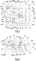
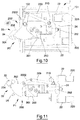
- the assembly 20 comprises a safety device 200 provided with a tappet 202 which has a fan portion 2021 at the base of which a fork stem 2022 is obtained. Said tappet 202 is carried in a rotatable manner by the frame 10 around a first pin 17 at the intersection between the fan portion 2021 and the stem 2022 from and towards an engagement position P1 of the seat 14 ( figures 6, 7 and 11 ).
- the fan portion 2021 has a substantially flat face 2023 ( figures 5 and 7 ) facing the seat 14 which is substantially spaced equal to the distance of a diameter of an axle AX1/AX2 from the bottom of the cylindrical surface 1440 of a hook 140/140' when the tappet 202 is in the engagement position P1.
- the tappet 202 engages the seat 14 at a substantially diametral distance of an axle AX1/AX2 and, therefore, is adapted to maintain an axle AX1/AX2 housed coincidingly in the seat 14 and to prevent said axle AX1/AX2 from moving from said position.
- Said first pin 17 is housed at the base of the stem 2022 and is oriented transversally to the direction D.
- the fan portion 2021 has a head portion 204 which can consist of a substantially C-shaped plate.
- the fan portion 2021 has a curved surface 20210 concentric to the first pin 17 which carries externally the head portion 204, which projects radially from the curved surface 20210, as can be seen in figures 8 and 9 .
- the safety device 200 further comprises a cam 206 carried integral and projecting from the connection member 24, therefore moving with a longitudinal translatory motion in the direction D, and mechanically coupled to the stem 2022 of the tappet 202 by means of a respective second pivot pin 2020 which is parallel to the first pin 17. Therefore the second pin 2020 has the function of alternately rotating the tappet 202 around the axis of the first pin 17 between the engagement position P1 and a disengagement position P2 ( figures 4, 5 and 10 ) of the seat 14, in which the tappet 202 is positioned substantially over the connection member 24, controlled by the linear actuator 260, the shaft 262 of which is completely extracted to maintain the first longitudinal pins 22/22' in the respective retracted position which can be seen in figure 4 .
- the cam 206 has a curved slot 208, the respective concavity of which faces the first pin 17. Said slot 208 is engaged by the second pin 2020 to couple the tappet 202 to the cam 206 bilaterally. As can be seen in figure 7 , the cam 206 engages a longitudinal cavity of the stem 2022.
- the safety device 200 operates by mechanical interference and is a cam-tappet mechanism that can be mechanically operated by the connection member 24, therefore directly by the locking assembly 20.
- the safety device 200 comprises a signalling assembly 30 positioned at the back (on the left in figures 2, 3 , 4 , 6 ) therefore facing an operator who occupies the cab of the operating machine known and not illustrated, on the arm of which, known and not illustrated, the quick coupling 1 has been installed by means of the adapter A.
- Said signalling assembly 30 comprises a covering element 18 (illustrated by a continuous line in figures 2, 3 , 5 and 7 and by a broken line in figures 4 and 6 ) carried integrally by the frame 10 between the sides 16/16' above the second wall 102 and, therefore, below the cover 5 and above the assembly 20 positioned partially over the seat 14.
- the signalling assembly 30 comprises a pair of signs 32 and 34 in contrasting colours provided in the element 18 facing the seat 14.
- a first sign 32 of the pair of signs 32/34 is located in the element 18 facing the seat 14 so as to be covered by the head portion 204 when, in use, the tappet 202 is in the engagement position P1 locking an axle AX1/AX2 housed in the seat 14.
- a second sign 34 of the pair of signs 32/34 is located beside the first sign 32 so as to be covered by the head portion 204 when, in use, the tappet 202 is arranged in the disengagement position P2 of the seat 14. In said condition the coupling 1 ensures the safety of the adapter A and any tools associated with it.
- the first sign 32 is in the form of a red circle
- the second sign 34 is in the form of a green circle. Therefore, when the first sign 32 can be seen (by an operator in a position lower than the coupling 1) then the tappet 202/the head 204 is in the disengagement position P2.
- the second sign 34 can be seen (by an operator in a position lower than the coupling 1) then it means that the tappet 202 has the respective head 204 in the engagement position P1 of the seat 14. If the operator is positioned higher than the two signs 32 and 34, it will be sufficient to rotate the adapter 1 by operating the mechanical arm that carries the adapter so that the face 2023 of the tappet 202 becomes visible to the operator.
- the coupling 1 is shaped to be used in a reversible manner. Furthermore, it is expedient to consider that when the shaft 262 of the linear actuator 260 is fully extracted from the respective armature 261, then the pins 22/22' are kept in the respective retracted position visible in figure 4 from the connection member 24, and the tappet 202 is arranged in the position P2 with the respective stem 2022 substantially transverse to the direction D, therefore parallel to the second wall 102; the respective fan portion 2021 is contained for the most part inside the chamber 100 and the respective head 204 faces a front portion of the seat 14, on the side of the wall 102.
- the tappet 202 is functionally in a neutral position, unable to interact with an axle AX1 or AX2 that may be contained in the seat 14 to retain it internally.
- the tappet 202 is in the respective position P1, over an axle AX1 or AX2 that may be contained in the seat 14, the same tappet 202 is functionally able to maintain the axle AX1/AX2 locked in the seat 14 or, in the absence of said axle AX1/AX2, the seat 14 is inaccessible to an axle AX1/AX2.
- the head 204 would be in a position at some distance from the first sign 32 in the form of a red circle which would be visible at the back. Therefore, an operator located in the cab, facing the back portion of the quick coupling 1, would be promptly visually informed of the occurrence of a potentially dangerous situation, in which every movement of the coupling 1 exerted by a movement of the arm that carries the quick coupling 1 could cause projection of the adapter and the elements connected to it.
- the element 18 is not essential for operation of the coupling 1.
- the pair of signs 32 and 34 with contrasting colours could be applied in the top of the cover 5 of the frame 10, particularly in the face of the cover 5 facing the tappet 202 and, particularly in the head portion 204 without modifying the scope of the present invention. Therefore, here and below, the expression “covering element” may indicate the element 18 or the cover 5.
- a variation 200' of the safety device 200 is illustrated in which operation of the tappet 202 that determines transformation of the translatory movement given by the reciprocating motion imparted by the shaft 262 of the actuator 260 to the connection member 24 is determined by a thrust mechanism.
- the crank consists of the stem 2022 of the tappet 202 and the connecting rod consists of a connecting rod 209 pivoted to the connection member 24 by means of a pin 210.
- the actuator 260 is mounted inside the chamber 100 with the armature 261 fixed to the frame 10 on the side of the second wall 102 instead of on the side of the first wall 101.
- the present invention concerns a mechanical type quick coupling provided with a hydraulically or mechanically operated mechanical interference safety device in which the locking device that operates the longitudinal locking pins is designed to operate the same safety device, after the first axle of the adapter has been loaded by the quick coupling, in addition to highlighting the successful coupling of the second axle or the impossibility of perfecting said coupling.
Landscapes
- Engineering & Computer Science (AREA)
- Mechanical Engineering (AREA)
- Mining & Mineral Resources (AREA)
- Civil Engineering (AREA)
- General Engineering & Computer Science (AREA)
- Structural Engineering (AREA)
- Quick-Acting Or Multi-Walled Pipe Joints (AREA)
- Seats For Vehicles (AREA)
- Pharmaceuticals Containing Other Organic And Inorganic Compounds (AREA)
- Fats And Perfumes (AREA)
- Component Parts Of Construction Machinery (AREA)
Applications Claiming Priority (1)
| Application Number | Priority Date | Filing Date | Title |
|---|---|---|---|
| IT102018000003422A IT201800003422A1 (it) | 2018-03-09 | 2018-03-09 | Attacco rapido |
Publications (2)
| Publication Number | Publication Date |
|---|---|
| EP3536862A1 true EP3536862A1 (de) | 2019-09-11 |
| EP3536862B1 EP3536862B1 (de) | 2021-05-05 |
Family
ID=62386836
Family Applications (1)
| Application Number | Title | Priority Date | Filing Date |
|---|---|---|---|
| EP19161403.1A Active EP3536862B1 (de) | 2018-03-09 | 2019-03-07 | Schnellwechsler |
Country Status (3)
| Country | Link |
|---|---|
| EP (1) | EP3536862B1 (de) |
| ES (1) | ES2875877T3 (de) |
| IT (1) | IT201800003422A1 (de) |
Cited By (3)
| Publication number | Priority date | Publication date | Assignee | Title |
|---|---|---|---|---|
| KR20210127333A (ko) * | 2020-04-14 | 2021-10-22 | 대모 엔지니어링 주식회사 | 퀵 체인지 오일퀵장치의 결합구조체 |
| KR20210127331A (ko) * | 2020-04-14 | 2021-10-22 | 대모 엔지니어링 주식회사 | 퀵 체인지 유압 커플링블록용 덮개개폐장치 |
| KR20210127332A (ko) * | 2020-04-14 | 2021-10-22 | 대모 엔지니어링 주식회사 | 퀵 체인지 수직타입 오일퀵 커플링용 덮개장치 |
Citations (5)
| Publication number | Priority date | Publication date | Assignee | Title |
|---|---|---|---|---|
| US6301811B1 (en) * | 2000-07-28 | 2001-10-16 | Gilmore Industries, Inc. | Coupler for a heavy-duty machine |
| WO2001077447A1 (en) * | 2000-04-10 | 2001-10-18 | Dick Dennis J | Power latched quick change attachment coupler |
| US20110286788A1 (en) * | 2010-03-26 | 2011-11-24 | Robert Sikorski | Coupler with pivoting front hook lock |
| EP2824243A1 (de) * | 2013-07-10 | 2015-01-14 | Cangini Benne S.R.L. | Schnellkupplung und zugehörige Verbindung an einer Werkzeug einer Arbeitsmaschine |
| DE102015210860A1 (de) * | 2015-06-12 | 2016-12-15 | Lehnhoff Hartstahl Gmbh & Co. Kg | Schnellwechsler |
-
2018
- 2018-03-09 IT IT102018000003422A patent/IT201800003422A1/it unknown
-
2019
- 2019-03-07 EP EP19161403.1A patent/EP3536862B1/de active Active
- 2019-03-07 ES ES19161403T patent/ES2875877T3/es active Active
Patent Citations (5)
| Publication number | Priority date | Publication date | Assignee | Title |
|---|---|---|---|---|
| WO2001077447A1 (en) * | 2000-04-10 | 2001-10-18 | Dick Dennis J | Power latched quick change attachment coupler |
| US6301811B1 (en) * | 2000-07-28 | 2001-10-16 | Gilmore Industries, Inc. | Coupler for a heavy-duty machine |
| US20110286788A1 (en) * | 2010-03-26 | 2011-11-24 | Robert Sikorski | Coupler with pivoting front hook lock |
| EP2824243A1 (de) * | 2013-07-10 | 2015-01-14 | Cangini Benne S.R.L. | Schnellkupplung und zugehörige Verbindung an einer Werkzeug einer Arbeitsmaschine |
| DE102015210860A1 (de) * | 2015-06-12 | 2016-12-15 | Lehnhoff Hartstahl Gmbh & Co. Kg | Schnellwechsler |
Cited By (3)
| Publication number | Priority date | Publication date | Assignee | Title |
|---|---|---|---|---|
| KR20210127333A (ko) * | 2020-04-14 | 2021-10-22 | 대모 엔지니어링 주식회사 | 퀵 체인지 오일퀵장치의 결합구조체 |
| KR20210127331A (ko) * | 2020-04-14 | 2021-10-22 | 대모 엔지니어링 주식회사 | 퀵 체인지 유압 커플링블록용 덮개개폐장치 |
| KR20210127332A (ko) * | 2020-04-14 | 2021-10-22 | 대모 엔지니어링 주식회사 | 퀵 체인지 수직타입 오일퀵 커플링용 덮개장치 |
Also Published As
| Publication number | Publication date |
|---|---|
| ES2875877T3 (es) | 2021-11-11 |
| EP3536862B1 (de) | 2021-05-05 |
| IT201800003422A1 (it) | 2019-09-09 |
Similar Documents
| Publication | Publication Date | Title |
|---|---|---|
| EP3536862B1 (de) | Schnellwechsler | |
| EP1599637B1 (de) | System umfassend ein gerätebefestigungsmittel und ein gerät | |
| EP0527733B1 (de) | Fahrzeug mit anzeigegerät für eine kupplung | |
| EP2076631B1 (de) | Kupplung für bagger | |
| US20110280648A1 (en) | Quick coupling device for work vehicles and machines in general | |
| EP1900880B1 (de) | Vorrichtung zur Verbindung eines Werkzeugs mit einem Antriebsmittel einer Arbeitsmaschine | |
| JP7189200B2 (ja) | クイック・カプラー | |
| ES2651813T3 (es) | Válvula de bloqueo, fijación de herramienta, una máquina de trabajo y el uso de una válvula de bloqueo | |
| US5467542A (en) | Coupling assembly and actuating mechanism therefor | |
| US20130330161A1 (en) | Locking mechanism for lift arm assembly | |
| EP2766529B1 (de) | Vordere bolzenverriegelung für eine zusatzvorrichtunges vorrichtung | |
| EP3312350B1 (de) | Vorrichtung für die kupplung zwichen arm und werkzeug einer arbeitsmaschine | |
| WO2003046297A2 (en) | Spread-style implement coupler for construction machines | |
| EP2768761B1 (de) | Fernaktivierung einer zylindrischen scherenhebevorrichtung | |
| EP1974963B1 (de) | Schleppvorrichtung für ein landwirtschaftliches oder industrielles Fahrzeug | |
| KR101739779B1 (ko) | 굴삭기의 스마트 집게용 처짐방지장치 | |
| US12385211B2 (en) | Assembly for securely coupling a tool on a working arm of a public works machine with improved operation | |
| JP5266060B2 (ja) | 油圧式連結装置用の安全装置 | |
| EP2540149A1 (de) | Traktorwerkzeuganbauvorrichtung | |
| AU2023203559A1 (en) | Quick coupler and quick coupler system with such a quick coupler | |
| US20170191240A1 (en) | Work Tool Coupler Engagement System | |
| KR102890639B1 (ko) | 원터치 안전고리를 구비하는 건설기계용 커플러 | |
| US12371870B2 (en) | Quick-change device having a control device with a mechanically and hydraulically controllable valve | |
| JP5779560B2 (ja) | 作業機装着装置 | |
| JPH09149703A (ja) | トラクタヒッチの電装カプラ |
Legal Events
| Date | Code | Title | Description |
|---|---|---|---|
| PUAI | Public reference made under article 153(3) epc to a published international application that has entered the european phase |
Free format text: ORIGINAL CODE: 0009012 |
|
| STAA | Information on the status of an ep patent application or granted ep patent |
Free format text: STATUS: THE APPLICATION HAS BEEN PUBLISHED |
|
| AK | Designated contracting states |
Kind code of ref document: A1 Designated state(s): AL AT BE BG CH CY CZ DE DK EE ES FI FR GB GR HR HU IE IS IT LI LT LU LV MC MK MT NL NO PL PT RO RS SE SI SK SM TR |
|
| AX | Request for extension of the european patent |
Extension state: BA ME |
|
| STAA | Information on the status of an ep patent application or granted ep patent |
Free format text: STATUS: REQUEST FOR EXAMINATION WAS MADE |
|
| 17P | Request for examination filed |
Effective date: 20200309 |
|
| RBV | Designated contracting states (corrected) |
Designated state(s): AL AT BE BG CH CY CZ DE DK EE ES FI FR GB GR HR HU IE IS IT LI LT LU LV MC MK MT NL NO PL PT RO RS SE SI SK SM TR |
|
| GRAP | Despatch of communication of intention to grant a patent |
Free format text: ORIGINAL CODE: EPIDOSNIGR1 |
|
| STAA | Information on the status of an ep patent application or granted ep patent |
Free format text: STATUS: GRANT OF PATENT IS INTENDED |
|
| INTG | Intention to grant announced |
Effective date: 20201028 |
|
| GRAS | Grant fee paid |
Free format text: ORIGINAL CODE: EPIDOSNIGR3 |
|
| GRAA | (expected) grant |
Free format text: ORIGINAL CODE: 0009210 |
|
| STAA | Information on the status of an ep patent application or granted ep patent |
Free format text: STATUS: THE PATENT HAS BEEN GRANTED |
|
| AK | Designated contracting states |
Kind code of ref document: B1 Designated state(s): AL AT BE BG CH CY CZ DE DK EE ES FI FR GB GR HR HU IE IS IT LI LT LU LV MC MK MT NL NO PL PT RO RS SE SI SK SM TR |
|
| REG | Reference to a national code |
Ref country code: GB Ref legal event code: FG4D |
|
| REG | Reference to a national code |
Ref country code: CH Ref legal event code: EP |
|
| REG | Reference to a national code |
Ref country code: AT Ref legal event code: REF Ref document number: 1389970 Country of ref document: AT Kind code of ref document: T Effective date: 20210515 |
|
| REG | Reference to a national code |
Ref country code: DE Ref legal event code: R096 Ref document number: 602019004336 Country of ref document: DE |
|
| REG | Reference to a national code |
Ref country code: IE Ref legal event code: FG4D |
|
| REG | Reference to a national code |
Ref country code: NL Ref legal event code: FP |
|
| REG | Reference to a national code |
Ref country code: LT Ref legal event code: MG9D |
|
| PG25 | Lapsed in a contracting state [announced via postgrant information from national office to epo] |
Ref country code: HR Free format text: LAPSE BECAUSE OF FAILURE TO SUBMIT A TRANSLATION OF THE DESCRIPTION OR TO PAY THE FEE WITHIN THE PRESCRIBED TIME-LIMIT Effective date: 20210505 Ref country code: LT Free format text: LAPSE BECAUSE OF FAILURE TO SUBMIT A TRANSLATION OF THE DESCRIPTION OR TO PAY THE FEE WITHIN THE PRESCRIBED TIME-LIMIT Effective date: 20210505 Ref country code: FI Free format text: LAPSE BECAUSE OF FAILURE TO SUBMIT A TRANSLATION OF THE DESCRIPTION OR TO PAY THE FEE WITHIN THE PRESCRIBED TIME-LIMIT Effective date: 20210505 Ref country code: BG Free format text: LAPSE BECAUSE OF FAILURE TO SUBMIT A TRANSLATION OF THE DESCRIPTION OR TO PAY THE FEE WITHIN THE PRESCRIBED TIME-LIMIT Effective date: 20210805 |
|
| REG | Reference to a national code |
Ref country code: ES Ref legal event code: FG2A Ref document number: 2875877 Country of ref document: ES Kind code of ref document: T3 Effective date: 20211111 |
|
| PG25 | Lapsed in a contracting state [announced via postgrant information from national office to epo] |
Ref country code: RS Free format text: LAPSE BECAUSE OF FAILURE TO SUBMIT A TRANSLATION OF THE DESCRIPTION OR TO PAY THE FEE WITHIN THE PRESCRIBED TIME-LIMIT Effective date: 20210505 Ref country code: SE Free format text: LAPSE BECAUSE OF FAILURE TO SUBMIT A TRANSLATION OF THE DESCRIPTION OR TO PAY THE FEE WITHIN THE PRESCRIBED TIME-LIMIT Effective date: 20210505 Ref country code: PT Free format text: LAPSE BECAUSE OF FAILURE TO SUBMIT A TRANSLATION OF THE DESCRIPTION OR TO PAY THE FEE WITHIN THE PRESCRIBED TIME-LIMIT Effective date: 20210906 Ref country code: LV Free format text: LAPSE BECAUSE OF FAILURE TO SUBMIT A TRANSLATION OF THE DESCRIPTION OR TO PAY THE FEE WITHIN THE PRESCRIBED TIME-LIMIT Effective date: 20210505 Ref country code: PL Free format text: LAPSE BECAUSE OF FAILURE TO SUBMIT A TRANSLATION OF THE DESCRIPTION OR TO PAY THE FEE WITHIN THE PRESCRIBED TIME-LIMIT Effective date: 20210505 Ref country code: NO Free format text: LAPSE BECAUSE OF FAILURE TO SUBMIT A TRANSLATION OF THE DESCRIPTION OR TO PAY THE FEE WITHIN THE PRESCRIBED TIME-LIMIT Effective date: 20210805 Ref country code: IS Free format text: LAPSE BECAUSE OF FAILURE TO SUBMIT A TRANSLATION OF THE DESCRIPTION OR TO PAY THE FEE WITHIN THE PRESCRIBED TIME-LIMIT Effective date: 20210905 Ref country code: GR Free format text: LAPSE BECAUSE OF FAILURE TO SUBMIT A TRANSLATION OF THE DESCRIPTION OR TO PAY THE FEE WITHIN THE PRESCRIBED TIME-LIMIT Effective date: 20210806 |
|
| PG25 | Lapsed in a contracting state [announced via postgrant information from national office to epo] |
Ref country code: SM Free format text: LAPSE BECAUSE OF FAILURE TO SUBMIT A TRANSLATION OF THE DESCRIPTION OR TO PAY THE FEE WITHIN THE PRESCRIBED TIME-LIMIT Effective date: 20210505 Ref country code: RO Free format text: LAPSE BECAUSE OF FAILURE TO SUBMIT A TRANSLATION OF THE DESCRIPTION OR TO PAY THE FEE WITHIN THE PRESCRIBED TIME-LIMIT Effective date: 20210505 Ref country code: DK Free format text: LAPSE BECAUSE OF FAILURE TO SUBMIT A TRANSLATION OF THE DESCRIPTION OR TO PAY THE FEE WITHIN THE PRESCRIBED TIME-LIMIT Effective date: 20210505 Ref country code: CZ Free format text: LAPSE BECAUSE OF FAILURE TO SUBMIT A TRANSLATION OF THE DESCRIPTION OR TO PAY THE FEE WITHIN THE PRESCRIBED TIME-LIMIT Effective date: 20210505 Ref country code: SK Free format text: LAPSE BECAUSE OF FAILURE TO SUBMIT A TRANSLATION OF THE DESCRIPTION OR TO PAY THE FEE WITHIN THE PRESCRIBED TIME-LIMIT Effective date: 20210505 Ref country code: EE Free format text: LAPSE BECAUSE OF FAILURE TO SUBMIT A TRANSLATION OF THE DESCRIPTION OR TO PAY THE FEE WITHIN THE PRESCRIBED TIME-LIMIT Effective date: 20210505 |
|
| REG | Reference to a national code |
Ref country code: DE Ref legal event code: R097 Ref document number: 602019004336 Country of ref document: DE |
|
| PLBE | No opposition filed within time limit |
Free format text: ORIGINAL CODE: 0009261 |
|
| STAA | Information on the status of an ep patent application or granted ep patent |
Free format text: STATUS: NO OPPOSITION FILED WITHIN TIME LIMIT |
|
| 26N | No opposition filed |
Effective date: 20220208 |
|
| PGFP | Annual fee paid to national office [announced via postgrant information from national office to epo] |
Ref country code: DE Payment date: 20220329 Year of fee payment: 4 |
|
| PG25 | Lapsed in a contracting state [announced via postgrant information from national office to epo] |
Ref country code: IS Free format text: LAPSE BECAUSE OF FAILURE TO SUBMIT A TRANSLATION OF THE DESCRIPTION OR TO PAY THE FEE WITHIN THE PRESCRIBED TIME-LIMIT Effective date: 20210905 Ref country code: AL Free format text: LAPSE BECAUSE OF FAILURE TO SUBMIT A TRANSLATION OF THE DESCRIPTION OR TO PAY THE FEE WITHIN THE PRESCRIBED TIME-LIMIT Effective date: 20210505 |
|
| PGFP | Annual fee paid to national office [announced via postgrant information from national office to epo] |
Ref country code: FR Payment date: 20220325 Year of fee payment: 4 |
|
| PGFP | Annual fee paid to national office [announced via postgrant information from national office to epo] |
Ref country code: NL Payment date: 20220326 Year of fee payment: 4 |
|
| PGFP | Annual fee paid to national office [announced via postgrant information from national office to epo] |
Ref country code: IT Payment date: 20220331 Year of fee payment: 4 Ref country code: ES Payment date: 20220401 Year of fee payment: 4 |
|
| PGFP | Annual fee paid to national office [announced via postgrant information from national office to epo] |
Ref country code: CH Payment date: 20220404 Year of fee payment: 4 |
|
| PG25 | Lapsed in a contracting state [announced via postgrant information from national office to epo] |
Ref country code: MC Free format text: LAPSE BECAUSE OF FAILURE TO SUBMIT A TRANSLATION OF THE DESCRIPTION OR TO PAY THE FEE WITHIN THE PRESCRIBED TIME-LIMIT Effective date: 20210505 |
|
| REG | Reference to a national code |
Ref country code: BE Ref legal event code: MM Effective date: 20220331 |
|
| PG25 | Lapsed in a contracting state [announced via postgrant information from national office to epo] |
Ref country code: LU Free format text: LAPSE BECAUSE OF NON-PAYMENT OF DUE FEES Effective date: 20220307 Ref country code: IE Free format text: LAPSE BECAUSE OF NON-PAYMENT OF DUE FEES Effective date: 20220307 |
|
| PG25 | Lapsed in a contracting state [announced via postgrant information from national office to epo] |
Ref country code: BE Free format text: LAPSE BECAUSE OF NON-PAYMENT OF DUE FEES Effective date: 20220331 |
|
| REG | Reference to a national code |
Ref country code: DE Ref legal event code: R119 Ref document number: 602019004336 Country of ref document: DE |
|
| REG | Reference to a national code |
Ref country code: CH Ref legal event code: PL |
|
| REG | Reference to a national code |
Ref country code: NL Ref legal event code: MM Effective date: 20230401 |
|
| GBPC | Gb: european patent ceased through non-payment of renewal fee |
Effective date: 20230307 |
|
| PG25 | Lapsed in a contracting state [announced via postgrant information from national office to epo] |
Ref country code: NL Free format text: LAPSE BECAUSE OF NON-PAYMENT OF DUE FEES Effective date: 20230401 |
|
| PG25 | Lapsed in a contracting state [announced via postgrant information from national office to epo] |
Ref country code: GB Free format text: LAPSE BECAUSE OF NON-PAYMENT OF DUE FEES Effective date: 20230307 |
|
| PG25 | Lapsed in a contracting state [announced via postgrant information from national office to epo] |
Ref country code: LI Free format text: LAPSE BECAUSE OF NON-PAYMENT OF DUE FEES Effective date: 20230331 Ref country code: GB Free format text: LAPSE BECAUSE OF NON-PAYMENT OF DUE FEES Effective date: 20230307 Ref country code: FR Free format text: LAPSE BECAUSE OF NON-PAYMENT OF DUE FEES Effective date: 20230331 Ref country code: DE Free format text: LAPSE BECAUSE OF NON-PAYMENT OF DUE FEES Effective date: 20231003 Ref country code: CH Free format text: LAPSE BECAUSE OF NON-PAYMENT OF DUE FEES Effective date: 20230331 |
|
| PG25 | Lapsed in a contracting state [announced via postgrant information from national office to epo] |
Ref country code: ES Free format text: LAPSE BECAUSE OF NON-PAYMENT OF DUE FEES Effective date: 20230308 |
|
| REG | Reference to a national code |
Ref country code: ES Ref legal event code: FD2A Effective date: 20240426 |
|
| PG25 | Lapsed in a contracting state [announced via postgrant information from national office to epo] |
Ref country code: MK Free format text: LAPSE BECAUSE OF FAILURE TO SUBMIT A TRANSLATION OF THE DESCRIPTION OR TO PAY THE FEE WITHIN THE PRESCRIBED TIME-LIMIT Effective date: 20210505 Ref country code: IT Free format text: LAPSE BECAUSE OF NON-PAYMENT OF DUE FEES Effective date: 20230307 Ref country code: ES Free format text: LAPSE BECAUSE OF NON-PAYMENT OF DUE FEES Effective date: 20230308 Ref country code: CY Free format text: LAPSE BECAUSE OF FAILURE TO SUBMIT A TRANSLATION OF THE DESCRIPTION OR TO PAY THE FEE WITHIN THE PRESCRIBED TIME-LIMIT Effective date: 20210505 |
|
| PG25 | Lapsed in a contracting state [announced via postgrant information from national office to epo] |
Ref country code: HU Free format text: LAPSE BECAUSE OF FAILURE TO SUBMIT A TRANSLATION OF THE DESCRIPTION OR TO PAY THE FEE WITHIN THE PRESCRIBED TIME-LIMIT; INVALID AB INITIO Effective date: 20190307 |
|
| PG25 | Lapsed in a contracting state [announced via postgrant information from national office to epo] |
Ref country code: MT Free format text: LAPSE BECAUSE OF FAILURE TO SUBMIT A TRANSLATION OF THE DESCRIPTION OR TO PAY THE FEE WITHIN THE PRESCRIBED TIME-LIMIT Effective date: 20210505 |
|
| REG | Reference to a national code |
Ref country code: AT Ref legal event code: MM01 Ref document number: 1389970 Country of ref document: AT Kind code of ref document: T Effective date: 20240307 |
|
| PG25 | Lapsed in a contracting state [announced via postgrant information from national office to epo] |
Ref country code: AT Free format text: LAPSE BECAUSE OF NON-PAYMENT OF DUE FEES Effective date: 20240307 |
|
| REG | Reference to a national code |
Ref country code: AT Ref legal event code: UEP Ref document number: 1389970 Country of ref document: AT Kind code of ref document: T Effective date: 20210505 |
|
| PG25 | Lapsed in a contracting state [announced via postgrant information from national office to epo] |
Ref country code: TR Free format text: LAPSE BECAUSE OF FAILURE TO SUBMIT A TRANSLATION OF THE DESCRIPTION OR TO PAY THE FEE WITHIN THE PRESCRIBED TIME-LIMIT Effective date: 20210505 |
|
| PGFP | Annual fee paid to national office [announced via postgrant information from national office to epo] |
Ref country code: AT Payment date: 20260410 Year of fee payment: 5 |