EP0051814B1 - Sondenanordnung für Verbrennungsmotoren - Google Patents
Sondenanordnung für Verbrennungsmotoren Download PDFInfo
- Publication number
- EP0051814B1 EP0051814B1 EP81109182A EP81109182A EP0051814B1 EP 0051814 B1 EP0051814 B1 EP 0051814B1 EP 81109182 A EP81109182 A EP 81109182A EP 81109182 A EP81109182 A EP 81109182A EP 0051814 B1 EP0051814 B1 EP 0051814B1
- Authority
- EP
- European Patent Office
- Prior art keywords
- microwave
- cavity
- probe
- probe assembly
- housing
- Prior art date
- Legal status (The legal status is an assumption and is not a legal conclusion. Google has not performed a legal analysis and makes no representation as to the accuracy of the status listed.)
- Expired
Links
Images


Classifications
-
- G—PHYSICS
- G01—MEASURING; TESTING
- G01M—TESTING STATIC OR DYNAMIC BALANCE OF MACHINES OR STRUCTURES; TESTING OF STRUCTURES OR APPARATUS, NOT OTHERWISE PROVIDED FOR
- G01M15/00—Testing of engines
- G01M15/04—Testing internal-combustion engines
- G01M15/10—Testing internal-combustion engines by monitoring exhaust gases or combustion flame
-
- F—MECHANICAL ENGINEERING; LIGHTING; HEATING; WEAPONS; BLASTING
- F02—COMBUSTION ENGINES; HOT-GAS OR COMBUSTION-PRODUCT ENGINE PLANTS
- F02B—INTERNAL-COMBUSTION PISTON ENGINES; COMBUSTION ENGINES IN GENERAL
- F02B2275/00—Other engines, components or details, not provided for in other groups of this subclass
- F02B2275/14—Direct injection into combustion chamber
-
- F—MECHANICAL ENGINEERING; LIGHTING; HEATING; WEAPONS; BLASTING
- F02—COMBUSTION ENGINES; HOT-GAS OR COMBUSTION-PRODUCT ENGINE PLANTS
- F02B—INTERNAL-COMBUSTION PISTON ENGINES; COMBUSTION ENGINES IN GENERAL
- F02B3/00—Engines characterised by air compression and subsequent fuel addition
- F02B3/06—Engines characterised by air compression and subsequent fuel addition with compression ignition
-
- Y—GENERAL TAGGING OF NEW TECHNOLOGICAL DEVELOPMENTS; GENERAL TAGGING OF CROSS-SECTIONAL TECHNOLOGIES SPANNING OVER SEVERAL SECTIONS OF THE IPC; TECHNICAL SUBJECTS COVERED BY FORMER USPC CROSS-REFERENCE ART COLLECTIONS [XRACs] AND DIGESTS
- Y02—TECHNOLOGIES OR APPLICATIONS FOR MITIGATION OR ADAPTATION AGAINST CLIMATE CHANGE
- Y02T—CLIMATE CHANGE MITIGATION TECHNOLOGIES RELATED TO TRANSPORTATION
- Y02T10/00—Road transport of goods or passengers
- Y02T10/10—Internal combustion engine [ICE] based vehicles
- Y02T10/12—Improving ICE efficiencies
Definitions
- the present invention relates to a probe assembly for detecting timing events in an internal combustion engine according to the preamble of claim 1.
- the interconnection cables When the interconnection cables are left connected to the probe, they tend to become entangled with other hardware as the probe is threaded into the selected glow plug opening.
- the cables are disconnected during the probe-insertion process, it is sometimes difficult to reattach the cables, and invariably deleterious wear occurs, especially with respect to the microwave connector.
- the problem to be so solved by the present invention is to provide a probe assembly according to the preamble of claim 1 the probe of which may be readily attached to an engine and connect the external diagnostic circuitry.
- the solution of the problem is given'in claim 1.
- the probe assembly is adapted to operate independently of coupler orientation with respect to the probe.
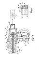
- FIGS. 1-4 illustrate one embodiment of a probe and coupler assembly 10 in accordance with the invention as comprising a dual probe 12, i.e. a probe for transmission of both microwave and optical energy as previously described, and a coupler 14 for connecting probe 12 to external diagnostic circuitry 15 (Fig. 2).
- a dual probe 12 i.e. a probe for transmission of both microwave and optical energy as previously described
- a coupler 14 for connecting probe 12 to external diagnostic circuitry 15 (Fig. 2).
- Such circuitry may take any number of forms, of which those shown in the above-noted Merio patents are two examples, the disclosures of such patents being incorporated herein by reference.
- Probe 12 comprises a generally tubular body 16 having external threads machined at one end 18 suitably for threading the probe into a cylinder opening of an internal combustion engine 19 (Fig. 2).
- threaded end 18 may advantageously be adapted for insertion into the glow plug opening of a selected engine cylinder or cylinder swirl chamber (with glow plug removed).
- the probe might also be held in without threads using an air cylinder sealed by an elastomeric collar, etc.
- At least a portion of the outer surface of tubular body 16 is provided with machined axially oriented flats 20 in a hexagonal pattern (Figs. 1 and 3) to receive a wrench or the like for tightening the probe in the cylinder opening so as to prevent escape of combustion gases, etc.
- the second end 22 of probe body 16 is provided with an internally threaded bore 24 (Fig. 2) coaxial with the central axis of body 16 and into which is threaded an energy transmission subassembly 26.
- subassembly 26 comprises an optical fiber 28 coaxial with probe body 16 and telescopically received into a hollow tubular metal microwave conductor 30.
- Conductor 30 is surrounded by a coaxial insulator 32 which is preferably constructed of optically transparent material so as to cooperate with fiber 28 for transmission of combustion luminescence.
- Insulator 32 is telescopically received in an outer sheath 34.
- the subassembly of fiber 28 through sheath 34 is received at one end into a plug 36 which is threaded into bore 24 of probe body 16 such that the telescoped assembly projects coaxially from end 18 of body 16.
- Insulator 32, microwave conductor 30 and optical fiber 28 project axially from both ends of outer sheath 34.
- a plug 40 Adjacent the threaded end 18 of probe body 16, a plug 40 is adhered over the coplanar ends of fiber 28, conductor 30 and insulator 32, plug 40 having a central opening 42 for transmitting light energy to fiber 28.
- Light energy from combustion luminescence similarly impinges radially on insulator 32 through the annular window 43 between plug 40 and the inner end of sheath 34.
- Diametrically opposed slotted openings 41 are formed in conductor 30 radially inwardly of window 43 for admitting a portion of the light energy received therethrough onto fiber 28.
- fiber 28, conductor 30 and insulator 32 project from the outer end of plug 36, while sheath 34 terminates coplanar therewith and is sealed thereto by the epoxy layer 44.
- the radially facing surface of that portion of plug 36 projecting axially from probe body 16 is cylindrical coaxially with probe body 16 and is provided with a circumferential channel 46 which operates as a microwave choke.
- coupler 14 is telescopically received over plug 36 for coupling microwave energy to conductor 30 and detecting transmission of optical energy by fiber 28 and/or insulator 32.
- Coupler 14 comprises a hollow body including a connector mounting block 50 having a rectangular channel 52 (Figs. 2 and 4) extending laterally along one face 51 thereof.
- a plate 54 is rigidly mounted to block 50 against face 51 by the side plates 55 so as to close channel 52 and thereby form, in cooperation with side plates 55, a laterally extending rectangular microwave cavity or waveguide.
- a cylindrical bore 56 extends through plate 54 and opens into the cavity 52 for mounting coupler 14 over the cylindrical outer surface of plug 36 such that fiber 28, microwave conductor 30 and insulator 32 project longitudinally and axially into cavity 52, as best seen in Fig. 2.
- a photodetector 58 is mounted on block 50 at a position along the bottom wall of cavity 52 coaxial with bore 56 in plate 54 so as to be aligned axially with optical fiber 28 and insulator 32 in assembly of coupler 14 with probe 12. Electrical chips and components may be potted into a module (not shown) attached to connector 62 to precondition (i.e., shape and amplify) the illuminance signal. Leads 60 electrically connect photodetector 58 to a connector 62 which is mounted by the screws 64 on an external surface of block 50 for electrically connecting photodetector 58 to external diagnostic circuitry 15.
- a SMA-type coax connector 66 is similarly mounted on block 50 at a position laterally spaced from the axis of bore 56 and probe 12.
- Connector 66 includes an elongated conductor 68 surrounded by an insulator 70 which project through block 50 into cavity 52 on an axis parallel with the axis of bore 56 and probe 12, and laterally spaced therefrom in assembly, as best seen in Fig. 2.
- the connector 66 is adapted to receive the usual coax type connector and cable for connecting conductor 68 to a microwave transceiver 72, and thence to diagnostic circuitry 15.
- Transceiver 72 may comprise a Microwave Associates oscillator MA-86210-M05, a Microwave Associater Circulator MA-8K220, an Omni- spectra coax adapter 2000-6255 and a Hewlett-Packard crystal detector P424A.
- probe 12 is first threaded into the glow plug opening of a selected cylinder as previously described, and coupler 14 with cables attached thereto is then telescopically and slidably engaged over plug 26 against the axial end of body 16.
- the detector is in a position to be responsive to light energy indicative of fuel ignition in the selected cylinder transmitted through fiber 28 and insulator 32.
- Microwave energy from transceiver 72 is coupled laterally through cavity 52 to conductor 30 projecting into cavity 52, and thence along conductor 30, which operates as a microwave transmission line, into the cylinder cavity.
- the microwave energy is radiated laterally from conductor 30 through the annular window 43 between plug 40 and outer sheath 34, window 43 being preferably about one- half wavelength in axial dimension.
- Microwave conductor 30 projects about one-quarter wavelength beyond protective sheath 34 into cavity 52.
- Bore 56 in plate 54 is preferably dimensioned for close sliding fit over the cylindrical outer surface of plug 36.
- Channel 46 which is preferably one- half wavelength in axial dimension, reduces leakage of microwave energy between plate 54 and plug 36.
- probe 12 which is relatively rugged, may be inserted using suitable tools into the cylinder opening.
- Coupler 14 which includes relatively more delicate components, and also the cable interconnections to remote diagnostic circuitry, may then be telescoped over plug 26 of probe 12 after the probe is fully installed onto the engine.
- Figs. 5 and 6 illustrate a modified embodiment of the invention wherein identical reference num- berals illustrate elements identical to those in the embodiment previously described in detail.
- the modified coupler 80 illustrated in Figs. 5 and 6 differs from the coupler 14 previously described primarily in that the microwave energy source and detector, i.e. the microwave transceiver 72 in Fig. 2, is mounted on the coupler. More particularly, coupler 80 includes a mounting plate 82 having a base 83 for telescopic engagement with plug 36 of probe 12, and a connector block 84 with photodetector 58 and a connector 86 mounted thereon.
- a laterally or radially extending channel 88 in connector block 84 cooperates with mounting plate 82 and the side plates 90 in the manner previously described for forming a microwave waveguide cavity.
- a microwave transceiver generally indicated at 92 is mounted on coupler 80 and includes an oscillator 94 and a circulator 96 having a suitable detector 98 mounted thereon.
- circulator 96 has a generally rectangular mouth 100 which opens onto cavity 88 for transmission of microwave energy from oscillator 94 to microwave conductor 30, and from conductor 30 to detector 98.
- Oscillator 94 and detector 98 are connected by suitable leads to connector 86, and thence to external diagnostic circuitry 15.
- Transceiver 92 may comprise a model MA-86857-M01 marketed by Microwave Associates. Operation of the embodiment of Figs. 5 and 6 will be self-evident from the foregoing discussion.
Landscapes
- Chemical & Material Sciences (AREA)
- Engineering & Computer Science (AREA)
- Combustion & Propulsion (AREA)
- Physics & Mathematics (AREA)
- General Physics & Mathematics (AREA)
- Testing Of Engines (AREA)
- Ignition Installations For Internal Combustion Engines (AREA)
Claims (7)
Applications Claiming Priority (2)
| Application Number | Priority Date | Filing Date | Title |
|---|---|---|---|
| US06/203,631 US4337648A (en) | 1980-11-03 | 1980-11-03 | Dual probe coupler |
| US203631 | 1980-11-03 |
Publications (2)
| Publication Number | Publication Date |
|---|---|
| EP0051814A1 EP0051814A1 (de) | 1982-05-19 |
| EP0051814B1 true EP0051814B1 (de) | 1985-10-16 |
Family
ID=22754704
Family Applications (1)
| Application Number | Title | Priority Date | Filing Date |
|---|---|---|---|
| EP81109182A Expired EP0051814B1 (de) | 1980-11-03 | 1981-10-29 | Sondenanordnung für Verbrennungsmotoren |
Country Status (4)
| Country | Link |
|---|---|
| US (1) | US4337648A (de) |
| EP (1) | EP0051814B1 (de) |
| JP (1) | JPS57108466A (de) |
| DE (1) | DE3172682D1 (de) |
Families Citing this family (23)
| Publication number | Priority date | Publication date | Assignee | Title |
|---|---|---|---|---|
| US4413509A (en) * | 1980-12-04 | 1983-11-08 | Robert Bosch Gmbh | Combustion process parameter sensor |
| US4373384A (en) * | 1981-07-23 | 1983-02-15 | Snap-On Tools Corporation | Diesel engine timing apparatus |
| ATE43406T1 (de) * | 1981-07-23 | 1989-06-15 | Ail Corp | Verfahren und einrichtung zur erzeugung eines verbrennungsbeginnsignal fuer eine selbszuendende brennkraftmaschine. |
| US4760830A (en) * | 1981-07-23 | 1988-08-02 | Ambac Industries, Incorporated | Method and apparatus for controlling fuel injection timing in a compression ignition engine |
| US4441021A (en) * | 1981-07-23 | 1984-04-03 | Snap-On Tools Corporation | Luminosity probe for diesel engine timing apparatus |
| DE3241390A1 (de) * | 1981-11-10 | 1983-05-19 | Nippondenso Co., Ltd., Kariya, Aichi | Brennstoffeinspritzvorrichtung fuer dieselmotore |
| JPS58204978A (ja) * | 1982-05-25 | 1983-11-29 | Toyota Central Res & Dev Lab Inc | 燃焼時期検出装置 |
| US4428229A (en) | 1982-06-01 | 1984-01-31 | General Motors Corporation | Means for establishing timing in diesel engines using microwave information |
| JPS59115473A (ja) * | 1982-12-22 | 1984-07-03 | Toyota Central Res & Dev Lab Inc | 燃焼時期検出装置 |
| JPS59116039A (ja) * | 1982-12-23 | 1984-07-04 | Toyota Central Res & Dev Lab Inc | マイクロ波・光プロ−ブ |
| US4493208A (en) * | 1982-12-29 | 1985-01-15 | Snap-On Tools Corporation | Dual engine probe |
| US4484469A (en) * | 1983-05-09 | 1984-11-27 | Snap-On Tools Corporation | Luminosity probe with positively retained light pipe |
| GB2154742B (en) * | 1984-02-21 | 1987-12-02 | Edeco Petroleum Services | Measuring length of electrical conductor |
| JPH0650066B2 (ja) * | 1984-08-20 | 1994-06-29 | 株式会社豊田中央研究所 | マイクロ波・光プロ−ブ |
| JPS6155311A (ja) * | 1984-08-27 | 1986-03-19 | Japanese National Railways<Jnr> | 燃焼室火炎像伝播材支持方法 |
| JPS61277416A (ja) * | 1985-06-04 | 1986-12-08 | Mitsubishi Plastics Ind Ltd | インサ−トが埋設された成形品の射出成形法 |
| JPS6228083U (de) * | 1985-08-05 | 1987-02-20 | ||
| JPH059504Y2 (de) * | 1985-08-06 | 1993-03-09 | ||
| GB8601842D0 (en) * | 1986-01-25 | 1986-02-26 | Lucas Ind Plc | Sensing device |
| SE508563C2 (sv) * | 1994-02-22 | 1998-10-12 | Scania Cv Ab | Sensor för detektering av joniseringsgrad i en förbränningsmotors förbränningsrum jämte förbränningsmotor försedd med joniseringssensor |
| US6182520B1 (en) * | 1999-04-15 | 2001-02-06 | General Electric Co. | Light probe installation |
| GB0117715D0 (en) * | 2001-07-19 | 2001-09-12 | Mrbp Res Ltd | Microwave biochemical analysis |
| US8841635B2 (en) | 2012-06-26 | 2014-09-23 | The United States Of America As Represented By The Secretary Of The Navy | Microwave induced visible luminescence |
Family Cites Families (7)
| Publication number | Priority date | Publication date | Assignee | Title |
|---|---|---|---|---|
| US3703825A (en) * | 1968-10-02 | 1972-11-28 | Merlo Angelo L | Combustion microwave diagnostic system |
| US3589177A (en) * | 1968-10-02 | 1971-06-29 | Merlo Angelo L | Combustion microwave diagnostic system |
| US3678741A (en) * | 1971-03-24 | 1972-07-25 | Gen Motors Corp | Engine combustion monitor |
| US3934566A (en) * | 1974-08-12 | 1976-01-27 | Ward Michael A V | Combustion in an internal combustion engine |
| JPS557972A (en) * | 1978-07-03 | 1980-01-21 | Matsushita Electric Ind Co Ltd | Internal combustor |
| JPS5547428A (en) * | 1978-10-02 | 1980-04-03 | Nissan Motor Co Ltd | Observing device for combustion chamber of internal combustion engine |
| DE2905506A1 (de) * | 1979-02-14 | 1980-09-04 | Bosch Gmbh Robert | Zuendbeginnsensor, insbesondere bei brennkraftmaschinen |
-
1980
- 1980-11-03 US US06/203,631 patent/US4337648A/en not_active Expired - Lifetime
-
1981
- 1981-10-29 DE DE8181109182T patent/DE3172682D1/de not_active Expired
- 1981-10-29 EP EP81109182A patent/EP0051814B1/de not_active Expired
- 1981-11-02 JP JP56176293A patent/JPS57108466A/ja active Granted
Also Published As
| Publication number | Publication date |
|---|---|
| EP0051814A1 (de) | 1982-05-19 |
| US4337648A (en) | 1982-07-06 |
| DE3172682D1 (en) | 1985-11-21 |
| JPS6220386B2 (de) | 1987-05-07 |
| JPS57108466A (en) | 1982-07-06 |
Similar Documents
| Publication | Publication Date | Title |
|---|---|---|
| EP0051814B1 (de) | Sondenanordnung für Verbrennungsmotoren | |
| US4393687A (en) | Sensor arrangement | |
| EP1086362B1 (de) | Zündkerze mit drucksensor | |
| US4090125A (en) | Ignition indicator for internal combustion engines | |
| US4422321A (en) | Combustion process sensor construction | |
| US6122971A (en) | Integrated fiber optic combustion pressure sensor | |
| EP0199224A3 (de) | Verfahren und System zur Überwachung der Position eines hydraulischen Stellorganes unter Verwendung der Mikrowellenresonanz in Hohlräumen | |
| US4413509A (en) | Combustion process parameter sensor | |
| EP0201749A2 (de) | Stecker mit einem beweglichen optoelektronischen Element | |
| EP0234928A3 (de) | Optische Faseranordnung | |
| EP1321785A3 (de) | Gegen elektromagnetische Interferenz abgeschirmter Adapter für faseroptische Verbindersysteme | |
| EP1092135B1 (de) | Zündkerze mit konzentrischem drucksensor | |
| US4409815A (en) | Combustion process sensor arrangement | |
| US4452072A (en) | Combustion condition sensor | |
| US4825689A (en) | Sensing device | |
| US4621519A (en) | Ballistics pressure transducer | |
| EP0048981B1 (de) | Mikrowellenadapter für eine Zündkerze | |
| CA1173904A (en) | Dual probe coupler | |
| US4545238A (en) | Microwave and luminous probe | |
| US4441021A (en) | Luminosity probe for diesel engine timing apparatus | |
| US4680960A (en) | Microwave and luminous probe | |
| US6882418B1 (en) | Device for monitoring the combustion processes occurring in the combustion chamber of an internal combustion engine | |
| US4506186A (en) | Spark plug and optical combustion sensor combination | |
| KR101219584B1 (ko) | 압력 센서를 구비한 예열 플러그의 헤드 | |
| JPS6217116B2 (de) |
Legal Events
| Date | Code | Title | Description |
|---|---|---|---|
| PUAI | Public reference made under article 153(3) epc to a published international application that has entered the european phase |
Free format text: ORIGINAL CODE: 0009012 |
|
| AK | Designated contracting states |
Designated state(s): BE DE FR GB IT |
|
| RBV | Designated contracting states (corrected) |
Designated state(s): BE DE FR GB IT |
|
| RBV | Designated contracting states (corrected) |
Designated state(s): BE DE FR IT |
|
| RBV | Designated contracting states (corrected) |
Designated state(s): BE DE FR IT |
|
| 17P | Request for examination filed |
Effective date: 19820827 |
|
| RBV | Designated contracting states (corrected) |
Designated state(s): BE DE FR IT |
|
| ITF | It: translation for a ep patent filed | ||
| GRAA | (expected) grant |
Free format text: ORIGINAL CODE: 0009210 |
|
| AK | Designated contracting states |
Designated state(s): BE DE FR GB IT |
|
| REF | Corresponds to: |
Ref document number: 3172682 Country of ref document: DE Date of ref document: 19851121 |
|
| ET | Fr: translation filed | ||
| PLBE | No opposition filed within time limit |
Free format text: ORIGINAL CODE: 0009261 |
|
| STAA | Information on the status of an ep patent application or granted ep patent |
Free format text: STATUS: NO OPPOSITION FILED WITHIN TIME LIMIT |
|
| 26N | No opposition filed | ||
| PG25 | Lapsed in a contracting state [announced via postgrant information from national office to epo] |
Ref country code: BE Effective date: 19861031 |
|
| BERE | Be: lapsed |
Owner name: JODON ENGINEERING ASSOCIATES INC. Effective date: 19861031 |
|
| PG25 | Lapsed in a contracting state [announced via postgrant information from national office to epo] |
Ref country code: FR Effective date: 19900629 |
|
| REG | Reference to a national code |
Ref country code: FR Ref legal event code: ST |
|
| PGFP | Annual fee paid to national office [announced via postgrant information from national office to epo] |
Ref country code: DE Payment date: 19900918 Year of fee payment: 10 |
|
| PGFP | Annual fee paid to national office [announced via postgrant information from national office to epo] |
Ref country code: GB Payment date: 19901001 Year of fee payment: 10 |
|
| PG25 | Lapsed in a contracting state [announced via postgrant information from national office to epo] |
Ref country code: GB Effective date: 19911029 |
|
| GBPC | Gb: european patent ceased through non-payment of renewal fee | ||
| PG25 | Lapsed in a contracting state [announced via postgrant information from national office to epo] |
Ref country code: DE Effective date: 19920701 |