EP0051842B1 - Abscheider magnetischer Partikel des Magnetförderbandtyps - Google Patents
Abscheider magnetischer Partikel des Magnetförderbandtyps Download PDFInfo
- Publication number
- EP0051842B1 EP0051842B1 EP81109451A EP81109451A EP0051842B1 EP 0051842 B1 EP0051842 B1 EP 0051842B1 EP 81109451 A EP81109451 A EP 81109451A EP 81109451 A EP81109451 A EP 81109451A EP 0051842 B1 EP0051842 B1 EP 0051842B1
- Authority
- EP
- European Patent Office
- Prior art keywords
- belt conveyor
- magnetic
- scrapers
- particle separator
- magnetic particle
- Prior art date
- Legal status (The legal status is an assumption and is not a legal conclusion. Google has not performed a legal analysis and makes no representation as to the accuracy of the status listed.)
- Expired
Links
- 239000006249 magnetic particle Substances 0.000 title claims description 54
- 239000007788 liquid Substances 0.000 claims description 4
- 238000005096 rolling process Methods 0.000 claims 1
- 239000003921 oil Substances 0.000 description 16
- 239000010730 cutting oil Substances 0.000 description 8
- 238000000926 separation method Methods 0.000 description 4
- 238000010276 construction Methods 0.000 description 3
- 230000004048 modification Effects 0.000 description 3
- 238000012986 modification Methods 0.000 description 3
- 239000011344 liquid material Substances 0.000 description 2
- 239000000463 material Substances 0.000 description 2
- CWYNVVGOOAEACU-UHFFFAOYSA-N Fe2+ Chemical compound [Fe+2] CWYNVVGOOAEACU-UHFFFAOYSA-N 0.000 description 1
- 238000009825 accumulation Methods 0.000 description 1
- 230000000694 effects Effects 0.000 description 1
- 229910052500 inorganic mineral Inorganic materials 0.000 description 1
- 239000006148 magnetic separator Substances 0.000 description 1
- 238000004519 manufacturing process Methods 0.000 description 1
- 239000011707 mineral Substances 0.000 description 1
- 238000005065 mining Methods 0.000 description 1
- 239000002245 particle Substances 0.000 description 1
- 229910001220 stainless steel Inorganic materials 0.000 description 1
- 239000010935 stainless steel Substances 0.000 description 1
Images


Classifications
-
- B—PERFORMING OPERATIONS; TRANSPORTING
- B03—SEPARATION OF SOLID MATERIALS USING LIQUIDS OR USING PNEUMATIC TABLES OR JIGS; MAGNETIC OR ELECTROSTATIC SEPARATION OF SOLID MATERIALS FROM SOLID MATERIALS OR FLUIDS; SEPARATION BY HIGH-VOLTAGE ELECTRIC FIELDS
- B03C—MAGNETIC OR ELECTROSTATIC SEPARATION OF SOLID MATERIALS FROM SOLID MATERIALS OR FLUIDS; SEPARATION BY HIGH-VOLTAGE ELECTRIC FIELDS
- B03C1/00—Magnetic separation
- B03C1/02—Magnetic separation acting directly on the substance being separated
- B03C1/16—Magnetic separation acting directly on the substance being separated with material carriers in the form of belts
- B03C1/22—Magnetic separation acting directly on the substance being separated with material carriers in the form of belts with non-movable magnets
Definitions
- This invention relates to a magnetic belt conveyor type magnetic particle separator according to the preamble of claim 1.
- Magnetic particle separators of that kind are used for separating magnetic particles from liquid containing such magnetic particles.
- the cutting oil or grinding oil having been used in factories generally contains indefinite numbers of magnetic particles. Such magnetic particles have to be removed by separation from the oil for the re-use thereof.
- a magnetic particle separator of the above mentioned kind is known from CH-A-376206.
- the protuberances of this separator are designed as transverse bars projecting from the outer surface of the belt conveyor to catch gathered and entangled masses of magnetic pieces tending to roll down the forward run end of the belt conveyor.
- very fine magnetic particles attracted from the magnet into the gap between the lower surface of the forward run of the belt conveyor and the upper surface of the magnet cannot be removed. This accumulation of magnet particles in the gap causes wear of the belt conveyor and reduces the magnetic force of the magnets.
- DE-B-1 128 812 discloses a magnetic separator whose magnetic poles are scraped by scraper bars mounted on a chain drive to remove hot ferrous material from the poles.
- a magnetic belt conveyor type magnetic particle separator of the above mentioned kind which comprises scrapers mounted on the inner side of the belt conveyor in a spaced-apart relation in the direction in which the belt conveyor runs and moved in unison therewith over the upper surface of the magnet means to scrape magnetic particles off the upper surface of the magnet means.
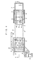
- a magnetic belt conveyor type magnetic particle separator includes an oil storage tank 1, a frame 2 and a belt conveyor 4. Cutting oil discharged from machine tools in a factory and containing magnetic particles is charged into the oil storage tank 1 in the direction of arrow A.
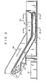
- One end portion of the frame 2 constitutes part of the side walls of the oil storage tank 1, and the other end portion of the frame 2 extends in an upwardly inclined direction from the oil storage tank.
- the frame 2 is supported by a pair of legs 3.
- the belt conveyor 4 is made of an oil- resistant, wear-proof belt material and disposed along the frame 2.
- the belt conveyor 4 has one end portion extending substantially horizontally along the portion of the frame 2 constituting the oil storage tank 1 and the other end portion extending in an upwardly inclined direction from the oil storage tank 1 along the other end portion of the frame. It is driven in the direction of arrow B.
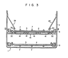
- a number of scrapers 5 are mounted in a uniformly spaced-apart relation in the direction of its running on its inner side (back side).
- Each scraper 5 is a rod member of a rectangular cross section extending in the direction perpendicular to the direction of running of the belt conveyor 4. Its length is greater than the width of the belt conveyor, and its opposite end portions project from the belt conveyor.
- Each scraper 5 is secured by screws 6 to the inner side of the belt conveyor 4.
- the belt conveyor 4 also has a number of protuberances, for instance spikes 7, projecting from its outer side (front side) and spaced apart at predetermined intervals in its running direction and transversal direction.
- end portions of the screws 6 penetrate the belt conveyor 4 to the outer side and serve as the spikes 7.
- the spikes 7 are preferably arranged in a staggered fashion in the running direction of the belt conveyor 4.
- the belt conveyor 4 of the above construction is driven by chains 8 provided on its opposite sides. More particularly, each end of the scraper 5 projected from the belt conveyor 4 is coupled by a connecting bolt 9 and a connecting piece 10 to the associated chain 8, as shown in Fig. 5.
- the chains 8 are passed round driven sprockets 12 and inverted sprockets 11 which are rotatably mounted on the frame 2, respectively and are disposed along the belt conveyor 4.
- the drive sprockets 12 are driven by a motor 13 mounted on the frame 2. As the chains 8 are driven by the motor 13 in the direction of arrow B, the belt conveyor 4 is run in the same direction together with the chains 8 via the scraper 5.
- An assembly 15 of magnets is disposed under the forward run of the belt conveyor 4 such that it extends in the direction of running of the belt conveyor.
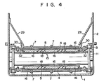
- the magnet assembly 15 includes, for instance, three permanent magnets 16 extending in the direction of running of the belt conveyor and arranged in a spaced-apart relation such that the width of the magnet assembly 15 is substantially the same as the width of the belt conveyor 4, and a case 17a and a lid 17b for accommodating the magnets 16.
- the case 17a is secured by support members 32 to the frame 2.
- the lid 17b is made of, for instance, a stainless steel plate.
- Each lower surface of the scraper 5 is slightly spaced apart from the upper surface of the lid 17b and moved parallel to the upper surface of the lid along it.
- each permanent magnet 16 constitutes an attenuating magnetic force magnet 19 as shown in Fig. 6.
- a magnetic particle receiving member 20 is connected to the left end of the magnet 15.
- a screw conveyor 21 is provided inside the receiving member 20. The screw conveyor 21 is rotated by a sprocket 20 meshing with one of the chains 8.
- a magnetic particle discharge outlet 23 is defined at one end of the receiving member 20.
- An oil return gutter 24 is disposed in the close proximity of the discharge outlet 23. The oil return gutter 24 communicates with the oil storage tank 1.
- a tensioning sprocket 25 and a magnet drum 26 are disposed adjacent to the drive sprockets 12 on the side of the backward run of the belt conveyor 4.
- the frame 2 has an opening formed at the end of its outwardly inclined portion, and a magnetic particle receptacle 27 is disposed beneath the opening.
- the upper side of the upwardly inclined portion of the frame 2 is covered by a cover 28.
- Hopper plates 29 are mounted on side wall portions of the frame 2 constituting the oil storage tank 1.
- the hopper plates 29 have respective filters 30, for instance made of sponge, and depending from their lower edges.
- Cutting oil supplied from machine tools is discharged into the oil storage tank 1 in the direction of arrow A.
- Magnetic particles contained in the cutting oil fall and are collected on the upper surface of the forward run of the belt conveyor 4.
- the magnetic particles are guided by the hopper plates 29 onto the upper surface of the belt conveyor 4.
- Magnetic particles approaching the upper surface of the belt conveyor 4 are attracted thereto by the magnetic forces of the magnet assembly 15.
- the belt conveyor 4 proceeds in the direction of arrow B, the magnetic particles attracted to the upper surface of the belt conveyor 4 are carried thereby up to the forward run end thereof.
- the magnetic particles are separated therefrom and fall into the magnetic particle receptacle 27 provided below.
- Magnetic particles remaining stuck to the belt conveyor 4 due to the viscosity of the cutting oil reach the magnet drum 6 where they are attracted to the side thereof and removed.
- Fibrous or strip-like magnetic pieces entangle one another into spherical masses before they are supplied together with oil to the oil storage tank 1. If the belt conveyor has a flat top surface, these spherical masses of magnetic pieces will roll over the belt conveyor and sometimes fail to be conveyed to the forward run end of the conveyor. Since the belt conveyor 4 according to the invention has the spikes 7 projecting from its upper surface, the masses of magnetic pieces are caught on the spikes 7. Thus, these masses of the magnetic pieces are reliably conveyed up to the forward run end of the belt conveyor 4 to be separated therefrom at that end and fall into the receptacle 27.
- the magnetic particles tending to accumulate in the gap between the lower surface of the belt conveyor 4 and the magnet assembly 15 are most effectively removed if the scrapers 5 are mounted such that their lower ends are in frictional contact with the upper surface of the lid 17b. In the instant embodiment, however, the scrapers 5 are mounted such that their lower end is slightly spaced apart from the lid 17b by taking the wear of the scrapers 5 and lid 17b into considerations.
- the screw conveyor 21 Since the screw conveyor 21 is provided inside the receiving plate 20, the magnetic particles having fallen into the receiving member 20 are conveyed by the screw conveyor 21 in the direction of arrow C to be discharged from the discharge outlet 23. Also, slight cutting oil having been transferred together with magnetic particles to the receiving member 20 is returned through the return gutter 24 to the oil storage tank 1.
- the screws 6 which secure the scrapers 5 to the belt conveyor 4 also serve as the spikes 7.
- the number of component parts is reduced to simplify the assembly and construction.
- spikes 7 and screws 6 are of course possible to use as separate parts.
- Fig. 8 shows a modification of the above embodiment.
- other scrapers 80 are provided on the outer side of the belt conveyor 4 as well.
- the conveyor 4 is thus sandwiched between these scrapers 80 and the aforementioned scrapers 5 provided on the inner side of the belt conveyor 4.
- the spikes 7 may again be constituted by the screws 6 securing the scrapers 5 and 80 to the belt conveyor 4 in the sandwiching relation thereto.
- the provision of the scrapers 80 on the upper surface of the belt conveyor 4 has an effect of still bettering the magnetic particle transport performance of the belt conveyor 4.
Landscapes
- Belt Conveyors (AREA)
- Auxiliary Devices For Machine Tools (AREA)
- Non-Mechanical Conveyors (AREA)
Claims (10)
Applications Claiming Priority (2)
| Application Number | Priority Date | Filing Date | Title |
|---|---|---|---|
| JP159294/80 | 1980-11-12 | ||
| JP55159294A JPS6028544B2 (ja) | 1980-11-12 | 1980-11-12 | マグネチックベルトコンベア式分離装置 |
Publications (2)
| Publication Number | Publication Date |
|---|---|
| EP0051842A1 EP0051842A1 (de) | 1982-05-19 |
| EP0051842B1 true EP0051842B1 (de) | 1984-08-15 |
Family
ID=15690642
Family Applications (1)
| Application Number | Title | Priority Date | Filing Date |
|---|---|---|---|
| EP81109451A Expired EP0051842B1 (de) | 1980-11-12 | 1981-10-31 | Abscheider magnetischer Partikel des Magnetförderbandtyps |
Country Status (5)
| Country | Link |
|---|---|
| US (1) | US4370228A (de) |
| EP (1) | EP0051842B1 (de) |
| JP (1) | JPS6028544B2 (de) |
| CA (1) | CA1164829A (de) |
| DE (1) | DE3165585D1 (de) |
Families Citing this family (22)
| Publication number | Priority date | Publication date | Assignee | Title |
|---|---|---|---|---|
| US4821754A (en) * | 1983-12-16 | 1989-04-18 | David R. Webb Co., Inc. | Flitch washer |
| JPH01139112A (ja) * | 1987-11-25 | 1989-05-31 | Nippon Shisutomeeshiyon Eng Kk | 瀘過装置 |
| EP0367518A3 (de) * | 1988-10-31 | 1991-04-10 | Nakamichi Corporation | Magnetbandreiniger |
| DE4209054A1 (de) * | 1991-05-04 | 1992-11-05 | Schloemann Siemag Ag | Bandfilter zum ausbringen von fremdstoffpartikeln aus fluessigkeitsbaedern |
| CA2123328A1 (en) * | 1993-12-13 | 1995-06-14 | Kimberly-Clark Worldwide, Inc. | Magnetic deinking |
| ES2206751T3 (es) * | 1996-12-01 | 2004-05-16 | Clifford Roy Warner | Dispositivo magnetico de descontaminacion. |
| US6086761A (en) * | 1998-02-24 | 2000-07-11 | American Phoenix, Inc. | Magnetic separator apparatus |
| US6325927B1 (en) * | 1997-02-24 | 2001-12-04 | Frederick H. Green | Magnetic separator apparatus |
| US6277276B1 (en) * | 2000-02-11 | 2001-08-21 | Jack R. Bratten | Filter apparatus with magnetic separation |
| KR100487489B1 (ko) * | 2000-09-27 | 2005-05-03 | 주식회사 포스코 | 냉간 압연유의 여과 장치 |
| US6946078B2 (en) * | 2002-02-27 | 2005-09-20 | Lynntech, Inc. | Electrochemical method and apparatus for producing and separating ferrate (VI) compounds |
| DE102004032334B3 (de) * | 2004-07-02 | 2005-10-20 | Mayfran Int Bv | Vorrichtung zur Aufnahme und Trennung von an Werkzeugmaschinen anfallenden Spänen und Kühlflüssigkeit (Transport) |
| US20060076285A1 (en) * | 2004-10-08 | 2006-04-13 | Lewandowski Leroy E | Contaminant removal and containment machine |
| DE102007010130B4 (de) * | 2007-02-28 | 2009-12-31 | Siemens Ag | Verfahren und Anordnung zur Separation von magnetischen Teilchen aus einer Substanz |
| CN101671075B (zh) * | 2008-09-08 | 2011-08-31 | 富葵精密组件(深圳)有限公司 | 废液回收装置及废液回收方法 |
| CN101590445B (zh) * | 2009-05-27 | 2011-12-21 | 镇江市江南矿山机电设备有限公司 | 交叉带式永磁磁选机 |
| US8505734B1 (en) | 2009-12-02 | 2013-08-13 | David C. Wise | Apparatus for removing magnetic materials |
| CN103657849B (zh) * | 2013-11-21 | 2016-03-02 | 武汉华翰液动机械有限责任公司 | 一种磁辊式过滤器 |
| CN111686935B (zh) * | 2020-06-18 | 2022-06-03 | 潍坊工程职业学院 | 一种高效式钢铁切削液过滤装置 |
| CN115646647B (zh) * | 2022-11-21 | 2023-03-10 | 太原陆森矿业机械有限公司 | 一种适用于湿式重介混合物的磁选机 |
| CN119897217B (zh) * | 2025-01-15 | 2026-02-10 | 昆明理工大学 | 一种自重力干式磁选摇床及其在含磁性矿物分选中的应用 |
| CN119897218B (zh) * | 2025-01-15 | 2026-02-10 | 昆明理工大学 | 一种含磁性物料的干法磁-重联合分选工艺 |
Family Cites Families (8)
| Publication number | Priority date | Publication date | Assignee | Title |
|---|---|---|---|---|
| DE1040165B (de) * | 1953-11-20 | 1958-10-02 | Friedrich Nagel | Reinigungsvorrichtung fuer fluessige Kuehl- und Spuelmittel |
| DE1128821B (de) * | 1958-03-06 | 1962-05-03 | Wagner K G | Elektromagnetscheider |
| CH376206A (de) * | 1960-02-09 | 1964-03-31 | Engler Werner | Selbstreinigender Magnetfilter, insbesondere zur Filtrierung der Kühlflüssigkeit von Drehbänken |
| US3094486A (en) * | 1960-06-22 | 1963-06-18 | Gleason Works | Magnetic separator |
| US3357559A (en) * | 1964-07-28 | 1967-12-12 | Eriez Magnetics | Endless belt magnetic separator with magnetic doffer |
| US3975275A (en) * | 1974-10-17 | 1976-08-17 | Shogo Kato | Conveyer for removing floating objects |
| US4025433A (en) * | 1976-01-22 | 1977-05-24 | Barnes Drill Co. | Magnetic separating apparatus |
| DE2710005C2 (de) * | 1977-03-08 | 1982-07-15 | Montanus Industrieanlagen Gmbh, 4300 Essen | Magnetfilteranlage |
-
1980
- 1980-11-12 JP JP55159294A patent/JPS6028544B2/ja not_active Expired
-
1981
- 1981-10-30 US US06/316,940 patent/US4370228A/en not_active Expired - Lifetime
- 1981-10-31 DE DE8181109451T patent/DE3165585D1/de not_active Expired
- 1981-10-31 EP EP81109451A patent/EP0051842B1/de not_active Expired
- 1981-11-12 CA CA000389972A patent/CA1164829A/en not_active Expired
Also Published As
| Publication number | Publication date |
|---|---|
| DE3165585D1 (en) | 1984-09-20 |
| JPS6028544B2 (ja) | 1985-07-05 |
| CA1164829A (en) | 1984-04-03 |
| US4370228A (en) | 1983-01-25 |
| JPS5784757A (en) | 1982-05-27 |
| EP0051842A1 (de) | 1982-05-19 |
Similar Documents
| Publication | Publication Date | Title |
|---|---|---|
| EP0051842B1 (de) | Abscheider magnetischer Partikel des Magnetförderbandtyps | |
| US5992642A (en) | Filtering apparatus and filtering system | |
| US4787500A (en) | Conveyor belt scraper | |
| EP1256417B1 (de) | Förderersystem zum Entfernern von Spänen | |
| JP3510611B2 (ja) | 分離機能を有する切粉搬出コンベヤ装置 | |
| US4302331A (en) | Filter bucket for a flight conveyor | |
| WO1995005986A1 (en) | Transfer method for plastic conveyor belts | |
| EP0024041B1 (de) | Mit Fördervorrichtung für Feststoffe versehene Filtervorrichtung | |
| US4731180A (en) | Water-solids separator and wiper blade | |
| US3362525A (en) | Magnetic beltscraper | |
| US5040549A (en) | Conveyors particularly for cutting machines | |
| JPS6371015A (ja) | 粉粒体搬送装置 | |
| EP0189171A2 (de) | Anlage zur Abtrennung von Spänen und Schneidstaub | |
| JPH0881031A (ja) | コンベア装置 | |
| JP3083272B2 (ja) | 切粉と切削油の分離装置 | |
| JP6111159B2 (ja) | 落鉱回収装置 | |
| JPS6243941Y2 (de) | ||
| GB2100211A (en) | Conveyor belt cleaning device | |
| JPS6116255Y2 (de) | ||
| JPH0351022Y2 (de) | ||
| JP2500812B2 (ja) | 脱液装置 | |
| GB2163974A (en) | Separation apparatus | |
| JP2591758Y2 (ja) | 切粉処理装置 | |
| JP4202531B2 (ja) | 液体回収手段を備えたヒンジコンベヤ装置 | |
| US4320842A (en) | Magnetic separator |
Legal Events
| Date | Code | Title | Description |
|---|---|---|---|
| PUAI | Public reference made under article 153(3) epc to a published international application that has entered the european phase |
Free format text: ORIGINAL CODE: 0009012 |
|
| 17P | Request for examination filed |
Effective date: 19811031 |
|
| AK | Designated contracting states |
Designated state(s): DE FR GB IT NL |
|
| ITF | It: translation for a ep patent filed | ||
| GRAA | (expected) grant |
Free format text: ORIGINAL CODE: 0009210 |
|
| AK | Designated contracting states |
Designated state(s): DE FR GB IT NL |
|
| REF | Corresponds to: |
Ref document number: 3165585 Country of ref document: DE Date of ref document: 19840920 |
|
| ET | Fr: translation filed | ||
| PLBE | No opposition filed within time limit |
Free format text: ORIGINAL CODE: 0009261 |
|
| STAA | Information on the status of an ep patent application or granted ep patent |
Free format text: STATUS: NO OPPOSITION FILED WITHIN TIME LIMIT |
|
| 26N | No opposition filed | ||
| ITTA | It: last paid annual fee | ||
| PGFP | Annual fee paid to national office [announced via postgrant information from national office to epo] |
Ref country code: FR Payment date: 19990915 Year of fee payment: 19 |
|
| PGFP | Annual fee paid to national office [announced via postgrant information from national office to epo] |
Ref country code: GB Payment date: 19991027 Year of fee payment: 19 Ref country code: DE Payment date: 19991027 Year of fee payment: 19 |
|
| PGFP | Annual fee paid to national office [announced via postgrant information from national office to epo] |
Ref country code: NL Payment date: 19991029 Year of fee payment: 19 |
|
| PG25 | Lapsed in a contracting state [announced via postgrant information from national office to epo] |
Ref country code: GB Free format text: LAPSE BECAUSE OF NON-PAYMENT OF DUE FEES Effective date: 20001031 |
|
| PG25 | Lapsed in a contracting state [announced via postgrant information from national office to epo] |
Ref country code: NL Free format text: LAPSE BECAUSE OF NON-PAYMENT OF DUE FEES Effective date: 20010501 |
|
| GBPC | Gb: european patent ceased through non-payment of renewal fee |
Effective date: 20001031 |
|
| PG25 | Lapsed in a contracting state [announced via postgrant information from national office to epo] |
Ref country code: FR Free format text: LAPSE BECAUSE OF NON-PAYMENT OF DUE FEES Effective date: 20010629 |
|
| NLV4 | Nl: lapsed or anulled due to non-payment of the annual fee |
Effective date: 20010501 |
|
| PG25 | Lapsed in a contracting state [announced via postgrant information from national office to epo] |
Ref country code: DE Free format text: LAPSE BECAUSE OF NON-PAYMENT OF DUE FEES Effective date: 20010703 |
|
| REG | Reference to a national code |
Ref country code: FR Ref legal event code: ST |