EP0052014B1 - Optical fiber connector and method of producing same - Google Patents
Optical fiber connector and method of producing same Download PDFInfo
- Publication number
- EP0052014B1 EP0052014B1 EP81305337A EP81305337A EP0052014B1 EP 0052014 B1 EP0052014 B1 EP 0052014B1 EP 81305337 A EP81305337 A EP 81305337A EP 81305337 A EP81305337 A EP 81305337A EP 0052014 B1 EP0052014 B1 EP 0052014B1
- Authority
- EP
- European Patent Office
- Prior art keywords
- plug
- optical fiber
- sleeve
- fiber connector
- filler
- Prior art date
- Legal status (The legal status is an assumption and is not a legal conclusion. Google has not performed a legal analysis and makes no representation as to the accuracy of the status listed.)
- Expired
Links
- 239000013307 optical fiber Substances 0.000 title claims description 135
- 238000000034 method Methods 0.000 title claims description 5
- 239000000945 filler Substances 0.000 claims description 24
- 239000000853 adhesive Substances 0.000 claims description 23
- 239000011521 glass Substances 0.000 claims description 23
- 229920003002 synthetic resin Polymers 0.000 claims description 15
- 239000000057 synthetic resin Substances 0.000 claims description 15
- 239000011324 bead Substances 0.000 claims description 13
- 239000002245 particle Substances 0.000 claims description 13
- 239000003822 epoxy resin Substances 0.000 claims description 11
- 230000002093 peripheral effect Effects 0.000 claims description 11
- 229920000647 polyepoxide Polymers 0.000 claims description 11
- 239000000463 material Substances 0.000 claims description 10
- 239000000314 lubricant Substances 0.000 claims description 9
- 239000000203 mixture Substances 0.000 claims description 8
- 229920000515 polycarbonate Polymers 0.000 claims description 8
- 239000004417 polycarbonate Substances 0.000 claims description 8
- 229920001343 polytetrafluoroethylene Polymers 0.000 claims description 8
- 239000004810 polytetrafluoroethylene Substances 0.000 claims description 8
- VYPSYNLAJGMNEJ-UHFFFAOYSA-N Silicium dioxide Chemical compound O=[Si]=O VYPSYNLAJGMNEJ-UHFFFAOYSA-N 0.000 claims description 6
- CWQXQMHSOZUFJS-UHFFFAOYSA-N molybdenum disulfide Chemical compound S=[Mo]=S CWQXQMHSOZUFJS-UHFFFAOYSA-N 0.000 claims description 6
- 229910052982 molybdenum disulfide Inorganic materials 0.000 claims description 6
- PNEYBMLMFCGWSK-UHFFFAOYSA-N aluminium oxide Inorganic materials [O-2].[O-2].[O-2].[Al+3].[Al+3] PNEYBMLMFCGWSK-UHFFFAOYSA-N 0.000 claims description 3
- 239000003960 organic solvent Substances 0.000 claims description 3
- -1 polytetrafluoroethylene Polymers 0.000 claims description 3
- OKTJSMMVPCPJKN-UHFFFAOYSA-N Carbon Chemical compound [C] OKTJSMMVPCPJKN-UHFFFAOYSA-N 0.000 claims description 2
- WNROFYMDJYEPJX-UHFFFAOYSA-K aluminium hydroxide Chemical compound [OH-].[OH-].[OH-].[Al+3] WNROFYMDJYEPJX-UHFFFAOYSA-K 0.000 claims description 2
- 238000004140 cleaning Methods 0.000 claims description 2
- 238000005520 cutting process Methods 0.000 claims description 2
- 239000000835 fiber Substances 0.000 claims description 2
- 239000010439 graphite Substances 0.000 claims description 2
- 229910002804 graphite Inorganic materials 0.000 claims description 2
- 239000011256 inorganic filler Substances 0.000 claims description 2
- 229910003475 inorganic filler Inorganic materials 0.000 claims description 2
- 238000000465 moulding Methods 0.000 description 13
- 238000003780 insertion Methods 0.000 description 10
- 230000037431 insertion Effects 0.000 description 10
- 230000003287 optical effect Effects 0.000 description 9
- 238000004891 communication Methods 0.000 description 7
- 238000009434 installation Methods 0.000 description 7
- 238000012360 testing method Methods 0.000 description 7
- 230000005540 biological transmission Effects 0.000 description 4
- 238000010276 construction Methods 0.000 description 4
- 229920005989 resin Polymers 0.000 description 4
- 239000011347 resin Substances 0.000 description 4
- 238000001816 cooling Methods 0.000 description 3
- 238000010586 diagram Methods 0.000 description 3
- 238000010438 heat treatment Methods 0.000 description 3
- 238000005461 lubrication Methods 0.000 description 3
- 239000004020 conductor Substances 0.000 description 2
- 230000000694 effects Effects 0.000 description 2
- 239000003365 glass fiber Substances 0.000 description 2
- 230000003746 surface roughness Effects 0.000 description 2
- 229920000049 Carbon (fiber) Polymers 0.000 description 1
- 230000001070 adhesive effect Effects 0.000 description 1
- 230000002238 attenuated effect Effects 0.000 description 1
- 239000004917 carbon fiber Substances 0.000 description 1
- 239000000919 ceramic Substances 0.000 description 1
- 230000008602 contraction Effects 0.000 description 1
- 230000006866 deterioration Effects 0.000 description 1
- 239000010437 gem Substances 0.000 description 1
- 229910010272 inorganic material Inorganic materials 0.000 description 1
- 239000011147 inorganic material Substances 0.000 description 1
- 238000007689 inspection Methods 0.000 description 1
- 238000012423 maintenance Methods 0.000 description 1
- 229910052751 metal Inorganic materials 0.000 description 1
- 239000002184 metal Substances 0.000 description 1
- 238000012544 monitoring process Methods 0.000 description 1
- 229920005668 polycarbonate resin Polymers 0.000 description 1
- 239000004431 polycarbonate resin Substances 0.000 description 1
- 239000000843 powder Substances 0.000 description 1
- 238000012545 processing Methods 0.000 description 1
- 230000002035 prolonged effect Effects 0.000 description 1
- 230000003014 reinforcing effect Effects 0.000 description 1
- 238000005096 rolling process Methods 0.000 description 1
- 238000007493 shaping process Methods 0.000 description 1
- 238000009628 steelmaking Methods 0.000 description 1
- 239000000126 substance Substances 0.000 description 1
- 229920005992 thermoplastic resin Polymers 0.000 description 1
- 229920001187 thermosetting polymer Polymers 0.000 description 1
- 238000009827 uniform distribution Methods 0.000 description 1
Images


Classifications
-
- G—PHYSICS
- G02—OPTICS
- G02B—OPTICAL ELEMENTS, SYSTEMS OR APPARATUS
- G02B6/00—Light guides; Structural details of arrangements comprising light guides and other optical elements, e.g. couplings
- G02B6/24—Coupling light guides
- G02B6/36—Mechanical coupling means
- G02B6/38—Mechanical coupling means having fibre to fibre mating means
- G02B6/3807—Dismountable connectors, i.e. comprising plugs
- G02B6/381—Dismountable connectors, i.e. comprising plugs of the ferrule type, e.g. fibre ends embedded in ferrules, connecting a pair of fibres
- G02B6/3825—Dismountable connectors, i.e. comprising plugs of the ferrule type, e.g. fibre ends embedded in ferrules, connecting a pair of fibres with an intermediate part, e.g. adapter, receptacle, linking two plugs
-
- G—PHYSICS
- G02—OPTICS
- G02B—OPTICAL ELEMENTS, SYSTEMS OR APPARATUS
- G02B6/00—Light guides; Structural details of arrangements comprising light guides and other optical elements, e.g. couplings
- G02B6/24—Coupling light guides
- G02B6/36—Mechanical coupling means
- G02B6/38—Mechanical coupling means having fibre to fibre mating means
- G02B6/3807—Dismountable connectors, i.e. comprising plugs
- G02B6/3833—Details of mounting fibres in ferrules; Assembly methods; Manufacture
- G02B6/3865—Details of mounting fibres in ferrules; Assembly methods; Manufacture fabricated by using moulding techniques
-
- G—PHYSICS
- G02—OPTICS
- G02B—OPTICAL ELEMENTS, SYSTEMS OR APPARATUS
- G02B6/00—Light guides; Structural details of arrangements comprising light guides and other optical elements, e.g. couplings
- G02B6/24—Coupling light guides
- G02B6/36—Mechanical coupling means
- G02B6/38—Mechanical coupling means having fibre to fibre mating means
- G02B6/3807—Dismountable connectors, i.e. comprising plugs
- G02B6/3833—Details of mounting fibres in ferrules; Assembly methods; Manufacture
- G02B6/3863—Details of mounting fibres in ferrules; Assembly methods; Manufacture fabricated by using polishing techniques
Definitions
- This invention relates to an optical fiber connector for connecting optical fibers together which are used as fiber-optic links in an optical communications system and a method of producing same.
- An optical information transmitting system or optical communications system has been developed as a promising system that would take over the electrical information transmitting system now widely in use.
- pulses of light generated on the transmission side are transmitted down fibers of glass or optical fibers of a thickness of one hundred to several hundreds of ⁇ m to the receiving side at which the pulses of light are converted into electric signals and taken out.
- a loss of light occur in the optical fiber connectors for connecting together the optical fibers forming links and built into telephone trunk networks, for example, for transmitting signals. Advances made in the progress of the art have made it possible to reduce the loss occurring within the optical fibers to the range between a fraction of and 1 dB/km. In the optical fiber connectors, however, the loss that might occur has its size decided by the amount of eccentricity of the axes of a pair of optical fibers abutted against each other by an optical fiber connector.
- the present practice in transmitting information over a long distance by utilizing an optical communications system is to mount repeaters in the fiberoptic links at suitable intervals for amplifying signals that have been attenuated, before being transmitted to the destination.
- the connection loss occurring in the optical fiber connectors is high, it would become necessary to increase the number of repeaters.
- An increase in the number of repeaters is not only undesirable from the economical point of view but also gives rise to many problems because it makes it necessary to perform maintenance and inspection more often and might reduce the reliability of the optical communications system as a whole.
- the optical fibers may vary from one another in length depending on the locations at which they are installed or the channels through which information is transmitted. Thus the operation of attaching a connector to the terminal ends of the optical fibers has been required to be performed readily at the site of installation.
- optical fiber connector should meet the requirements of low connection loss and easy assembly.
- the optical fiber connector usually comprises a plug formed with a flange in an intermediate portion on its outer peripheral surface and a bore for containing an optical fiber in its center axial portion, a sleeve formed at its center axis with a through hole for fitting the outer peripheral surface of the plug and on its outer peripheral surface with threads, a cap nut adapted to threadably engage the thread generated in the sleeve, and a spring mounted between the plug and the cap nut for keeping constant the abutting force exerted by the plug.
- the accuracy in positioning an optical fiber owes largely to the accuracy in positioning the plug and sleeve relative to each other. In this respect, what is most important is how to minimize deviation of the axis of the plug from the axis of the optical fiber.
- One type has its outer case formed of hard metal which has a double eccentric cylinder built therein and the other type has a guide of jewels or ceramics embedded in the center axis and formed with a bore of a diameter slightly greater than that of the optical fiber.
- the plug having a guide embedded therein has the forward end of the optical fiber positioned by the guide, so that this type offers the advantage of the installation at the site being greatly improved.
- working of the plug or aperturing the guide to an accuracy of the order of a fraction of a millimeter would require highly advanced skills and a prolonged time to carry out, so that the operation would be very low in productivity.
- An object of this invention is to provide an optical fiber connector enabling optical fibers to be assembled readily and with a high degree of precision at the site of installation at which connection of optical fibers is required to be effected.
- Another object is to provide a method of producing an optical fiber connector enabling the optical fiber connector to be assembled readily and with a high degree of precision at the site of installation.
- an optical fiber connector comprising a plug adhesively attached to an end of an optical fiber cable, a sleeve threaded at each end of an outer peripheral surface thereof and adapted to have said plug inserted from an end into a center axial portion thereof, a cap nut threaded at one end of an inner peripheral surface thereof for fixing the plug to the sleeve, and a spring mounted on an outer peripheral portion of the plug so as to be located between the plug and the cap nut, the said plug and said sleeve both having been molded from a synthetic resin material containing an inorganic filler, characterised in that the filler comprises glass beads, glass balloons or silica glass in particle form, and in that the adhesive agent comprises an epoxy resin base adhesive agent of below 20 poise in viscosity added as a filler with 40-60 wt% of alumina or aluminum hydroxide in particle form of mean particle size which is 50-70% of the clearance between an orifice of the plug and the optical fiber.
- the use of the fine glass filler provides particularly good precision molding properties ensuring accurate dimensioning of the formed connector, while the adhesive provided with a particle filler having a particular particle size ensures accurate alignment of the optical fiber in the accurately molded plug orifice.
- the present invention also relates to a method of producing an optical fiber connector comprising the steps of:
- FIG. 1 shows an optical fiber connector 5 comprising one embodiment of the invention being used for connecting optical fibers.
- An optical fiber cable 1 comprises an optical fiber 2 for transmitting light signals, a primary coat 3 for reinforcing the optical fiber 2, and a secondary coat 4 overlying the primary coat 3.
- the optical fiber connector 5 includes a plug 6 molded cylindrically in such a manner that a bore 7 for receiving the optical fiber cable 1 from which the secondary coat 4 is removed and an orifice 8 for receiving the optical fiber 2 communicate with each other at the center axis of the plug 6.
- a flange 9 is formed on the central portion of the outer peripheral surface of the plug 6.
- a sleeve 10 has molded therein a through hole 11 for receiving the plug 6.
- the hole 11 has tapering guide portions 12 located at opposite ends of the hole and diverging outwardly toward the open ends of the hole.
- the sleeve 10 has a flange 13 molded on the central portion of its outer peripheral surface and is provided with external threads 14 at each end.
- a pair of cap nuts 15 are each molded cylindrically with a through hole 17 molded therein which slidably receives a respective plug and has an inwardly projecting flange 16.
- the through hole 17 is molded at one end with internal threads 18 for engaging the threads 14 molded on the sleeve 10.
- a spring 19 is provided about the outer periphery of the plug 6 so as to be interposed between the flanges 9 and 16.
- the plug 6 and the secondary coat 4 of the optical fiber cable 1 are connected together as a unit by a clamp ring 20 and a cable cap 21, so as to avoid an inserting and withdrawing force being exerted on the optical fiber 2 when the plug 6 is inserted and withdrawn with respect to the sleeve 10.
- the optical fiber connector 5 is assembled as follows.
- the optical fiber cable 1, plug 6, sleeve 10, cap nut 15, spring 19, clamp ring 20 and cable cap 21 are molded in the respective shapes at the plant and transported to the site of installation individually.
- the cable cap 21, clamp ring 20, cap nut 15 and spring 19 are inserted in the indicated order on the end of the optical fiber cable 1 and moved to the position where they do not interfere with operations.
- the exposed optical fiber 2 of the optical fiber cable 1 is washed with an organic solvent.
- the optical fiber cable 1 is inserted at one end into the bore 7 of the plug 6 and forced thereinto until a suitable length of the end of the optical fiber 2 projects from the orifice 8.
- the forward end portion of the plug 6 is held and the cap nu t 15 is moved toward the front end of the plug 6 until the spring 19 is fully compressed and is held in that position.
- the clamp ring 20 is positioned such that one end thereof is applied to the plug 6 and the other end thereof is applied to the secondary coat 4 of the optical fiber cable 1, and the clamp ring 20 is adhesively attached to the plug 6 and the secondary coat 4.
- the cable cap 21 is adhesively attached to the secondary coat 4. Then, the cap nut 15 is released and subjected to a retracting force from the end of the optical fiber 2 by the biasing force of the spring 19. The portion of the optical fiber 2 projecting from the forward end of the plug 6 is then severed so that the end of the optical fiber 2 is aligned with the end of the plug 6. The plug is inserted in a jig for lapping to grind the forward end portion of the plug 6. After it has been subjected to lapping until a required surface roughness is attained, the plug 6 and the optical fiber 2 have their surfaces washed. Then, the plug 6 is inserted into the sleeve 10 and clamped by the cap nut 15, thereby completing connection of the optical fiber cable 1 by the optical fiber connector 5.
- the bore 7 of the plug 6 and the space between the optical fiber 2 and the primary coat 3 as well as the space between the orifice 8 and the optical fiber 2 are filled with an adhesive agent.
- the sleeve 10 and the cap nut 15 of the optical fiber connector 5 are molded by a shaping process known in the art.
- the plug 6 is molded with a mold shown in Fig. 2 in its essential portions only.
- the portions of the mold not shown are similar to those of a known mold of triad construction.
- an lock pin 31 projects from a stationary mounting plate 30, and a stationary cavity retainer plate 32 has a stationary cavity 33 for defining the outer periphery of the forward end portion of the plug 6 embedded therein and having at one end thereof a stationary core 34 defining the forward end face of the plug 6 embedded therein.
- the stationary core 34 is formed therein with air vents 35 for evacuating a cavity.for defining the plug 6, and a dummy cavity 36 communicating with the air vents 35 and storing therein the air from the aforesaid cavity.
- a stationary core pin 37 slightly thicker than the optical fiber 2 of the optical fiber cable 1 projects from the end face of the stationary core 34 at its central portion.
- a movable cavity retainer plate 38 has embedded therein a movable cavity 39 for defining the flange 9 of the plug 6 and the outer periphery of the rear end thereof.
- the movable cavity retainer plate 38 and the movable cavity 39 have a groove 40 of disc shape formed therein for providing a disc shaped runner between the movable cavity retainer ptate 38 and the stationary cavity retainer plate 32, and an annular gate is provided between an annular projection 41 formed on the movable cavity 39 and the stationary cavity retainer plate 32.
- the movable cavity 39 has an ejector pin 42 slidably inserted therein for defining the rear end face of the plug 6.
- the ejector pin 42 has slidably inserted in its center axis a movable core pin 43 having a diameter larger than the outer diameter of the secondary coat 4 of the optical fiber cable 1, so that when the mounting plates are clamped together the forward end of the movable core pin 43 abuts against the stationary core pin 37.
- the synthetic resin 44 flows into the cavity defined by the stationary cavity 33, stationary core 34, stationary core pin 37, movable cavity 39, movable core pin 43 and ejector pin 42 after passing through the gate following filling of the runner, to form the plug 6.
- that air which is not released through the interface between the mounting plates and gaps between the parts flows through the air vents 35 to be forced into the second cavity.
- the mounting plates are released from each other. First of all, the movable cavity retainer plate 38 is moved rearwardly. This moves the molded plug 6 together with the movable cavity retainer plate 38.
- the synthetic resin in the air vents 35 is ruptured, to separate the plug 6 from the synthetic resin in the second cavity.
- Rearward movement of the movable cavity retainer plate 38 actuates the ejector pin 42 which ejects the plug 6 from the movable cavity 39 and the stationary core pin 37.
- the stationary cavity retainer plate 32 moves together with the movable cavity retainer plate 38, to be separated from the stationary mounting plate 30.
- the synthetic resin set in the second cavity catches against the lock pin 31 and remains on the stationary mounting plate 30, so that the synthetic resin set in the air vents 35 and the dummy cavity 36 of the stationary core 34 can be removed. While the parts are in this condition, the synthetic resin that has set is removed from the lock pin 31.
- the plug 6 By molding the plug 6 by using a core pin attached to the core for defining the forward end face of the plug 6 for molding the orifice 8 for receiving the optical fiber 2 of the optical fiber cable 1, it is possible to ' achieve positioning of the orifice 8 with respect to the plug 6 with a very high degree of precision.
- the provision of the second cavity is conducive to increase dimensional accuracy of the forward end portion of the plug 6.
- the plug 6 may be molded of either a thermosetting resin or thermoplastic resin.
- a synthetic resin When a synthetic resin is used singly, the hardness thereof is very low with respect to the optical fiber 2 of the optical fiber cable 1. The result of this would be that the length of the optical fiber 2 sticking out of the end face of the plug 6 would be large when the end face of the plug 6 is lapped.
- a filler of inorganic material is added to the synthetic resin to increase the hardness of the plug 6.
- the filler may be glass beads, glass balloons or silica glass particles.
- the plug 6 was molded by using a mold shown in Fig. 2 and tested for its dimensions and connection characteristics as shown in Figs. 3 and 4, to pass judgement on whether or not the plug 6 is acceptable for specifications.
- Polycarbonate which is commercially available was used as the synthetic resin and the filler was selected from the group consisting of glass fibers, carbon fibers and glass beads of a mean particle size of 10 pm.
- connection loss of below 1 dB and the distance between the end face of plug 6 and the end of optical fiber 2 of below 4 um at the maximum.
- the results of the tests are shown in Table 1.
- the connection loss shown in Table 1 (and Tables 2-4) was determined with a fitting clearance 0 between plug 6 and sleeve 10.
- the mixture of polycarbonate with 9.5-30.2 wt% of glass beads as a filler is suitable for producing an optical fiber connector.
- glass beads, glass balloons or silica glass may be used as a filler.
- the proportion of the glass beads added to the polycarbonate is preferably 10-30%.
- connection loss was tested following insertion and withdrawing performed for 200 times. To the standards of judgement described hereinabove, a connection loss of less than 0.2 dB following the insertion and withdrawing of 200 times was added for the connection loss occurring in initial periods.
- the mixture used for molding the plug 6 contained polycarbonate and 30 wt% of glass beads.
- MoS 2 When MoS 2 is used as a filler, the content in the range between 1 and 5% is optimum.
- the amount of the lubricant necessary for application to compensate for insertion and withdrawing of the plug 6 was the subject of study in the same manner as described by referring to example 1.
- the specimens used in the tests consisted of an epoxy resin added with silica glass in 69 wt%, and the lubricants included PTFE, MoS 2 and graphite.
- the amount of the lubricant added is preferably in the range between 1 and 5 wt% for achieving best lubrication effects and obtaining optimum formability.
- the outer diameter D, (Fig. 4) of the optical fiber 2 of the optical fiber cable 1 and the inner diameter d, (Fig. 3) of the orifice 8 of the plug 6 and the outer diameter D 2 (Fig. 3) of the forward end portion of the plug 6 and the inner diameter d 2 (Fig. 5) of the through hole 11 of the sleeve 10 be controlled.
- the inner diameter d, of the orifice 8 has only to be made equal to the outer diameter D, of the optical fiber 2.
- the inner diameter d, of the orifice 8 were equal to the outer diameter D, of the optical fiber 2
- difficulties would be experienced in passing the optical fiber 2 through the orifice 8 and in addition no gaps would be formed between the orifice 8 and optical fiber 2 for admitting the adhesive agent thereinto.
- the diameter d, were larger than the outer diameter D, of the orifice 8 eccentricity of the axes of the orifice 8 and the conductor 2 would become great.
- the inner diameter d, of the orifice 8 should be larger than the outer diameter D, of the optical fiber 2 by 1-2 ⁇ m. This facilitates insertion of the optical fiber 2 in the orifice 8 and makes it possible to restrict the eccentricity of the orifice 8 and optical conductor 2 to 0.5-1 pm, in addition to facilitating admission of the adhesive agent between the optical fiber 2 and orifice 8 to achieve bonding between them.
- the outer diameter D 2 of the plug 6 and the inner diameter d 2 of the sleeve 10 are decided by the force exerted for inserting and withdrawing the plug 6 and the connection loss.
- Fig. 6 shows the force for inserting and withdrawing the plug 6 with respect to the sleeve 10 in relation to the connection loss, it being assumed that the difference (D 2- d 2 ) between the outer diameter D 2 of the plug 6 and the inner diameter d 2 of the sleeve provides a clearance necessary for fitting the plug 6 in the sleeve 10.
- A represents the insertion and withdrawing force
- B indicates the connection loss
- the plug 6 and the sleeve 10 used in combination were molded of an epoxy resin added with 69% of filler.
- Fig. 7 shows the number of times the plug is inserted and withdrawn in relation to changes in the connection loss with respect to a connection loss of the initial stages.
- a represents the fitting clearance being -3 ⁇ m at initial stages
- b indicates the fitting clearance being -2 ⁇ m at initial stages.
- connection loss including the influences of insertion and withdrawing of the plug 6 to a level below 1 dB if the fitting clearance of the plug 6 in the sleeve 10 were set in the range between -3 and +2 ⁇ m.
- Fig. 8 shows the influences exerted by the combination of the plug 6 and the sleeve 10 on connection losses.
- A1 represents the sleeve 10 formed of an epoxy resin and the plug 6 of polycarbonate and B1 represents the plug 6 and sleeve 10 both formed of an epoxy resin (the fitting clearance is 0 when the temperature is 22 degrees).
- the influences of the temperature can be eliminated if the same material is used.
- the plug 6 and the sleeve 10 are preferably formed of the same material.
- An adhesive agent of low viscosity (below 20 poise) is used as an adhesive agent.
- a filler By adding a filler to the adhesive agent, it is possible to reduce the eccentricity of the center axis of the optical fiber 2 of the optical fiber cable 1 with respect to the center axis of the orifice 8 of the plug 6.
- the mean particle size of the filler is about 50-70% of the clearance between the orifice 8 and the optical fiber 2.
- a suitable material should be selected for the filler.
- Fig. 9 shows another embodiment of the invention wherein parts similar to those shown in Fig. 1 are designated by like reference characters.
- a glass tube 25 is attached to the optical fiber 2 of the optical fiber cable 1 and inserted in the bore 7 of the plug 6 where it is adhesively bonded to the plug pin 6 and the optical fiber 2.
- optical fiber connector according to the invention lends the optical fiber connector according to the invention to applications in which the connector is installed in places of large variations in temperature where the connector is subjected to repeated heating and cooling, for a monitoring system for the piping or processing devices of chemical plants or a data transmission system built in the rolling mill of a steel making plant, for example.
- the difference in thermal expansion between the optical fiber 2 of the optical fiber cable 1 and the plug 6 and the adhesive agent causes peeling of the adhesive agent, and when the adhesive agent is pushed out of the forward end of the plug 6 by thermal expansion, the optical fiber 2 is simultaneously pushed out. This reduces the reliability of the optical fiber connector 5 used in transmission of information.
- This disadvantage can be eliminated by using the glass tube 25, because the optical fiber 2 is restrained by the glass tube 25 and prevented from sticking out of the plug 6 even if subjected to repeated heating and cooling.
Landscapes
- Physics & Mathematics (AREA)
- General Physics & Mathematics (AREA)
- Optics & Photonics (AREA)
- Mechanical Coupling Of Light Guides (AREA)
Description
- This invention relates to an optical fiber connector for connecting optical fibers together which are used as fiber-optic links in an optical communications system and a method of producing same.
- An optical information transmitting system or optical communications system has been developed as a promising system that would take over the electrical information transmitting system now widely in use. In an optical communications system, pulses of light generated on the transmission side are transmitted down fibers of glass or optical fibers of a thickness of one hundred to several hundreds of µm to the receiving side at which the pulses of light are converted into electric signals and taken out.
- In this type of optical communications system, the most important problem is how to transmit information from the transmission side to the receiving side with a high degree of efficiency in a stable manner.
- In the optical communications system, a loss of light occur in the optical fiber connectors for connecting together the optical fibers forming links and built into telephone trunk networks, for example, for transmitting signals. Advances made in the progress of the art have made it possible to reduce the loss occurring within the optical fibers to the range between a fraction of and 1 dB/km. In the optical fiber connectors, however, the loss that might occur has its size decided by the amount of eccentricity of the axes of a pair of optical fibers abutted against each other by an optical fiber connector. For example, in the case of an optical fiber of 125 pm in diameter, if the axes of the optical fibers abutted against each other are off-center by about 4 um, a connection loss of about 0.5 dB would occur, if the eccentricity is about 7 pm, the loss would be 1 dB.
- Thus the present practice in transmitting information over a long distance by utilizing an optical communications system is to mount repeaters in the fiberoptic links at suitable intervals for amplifying signals that have been attenuated, before being transmitted to the destination. In this case, if the connection loss occurring in the optical fiber connectors is high, it would become necessary to increase the number of repeaters. An increase in the number of repeaters is not only undesirable from the economical point of view but also gives rise to many problems because it makes it necessary to perform maintenance and inspection more often and might reduce the reliability of the optical communications system as a whole.
- The optical fibers may vary from one another in length depending on the locations at which they are installed or the channels through which information is transmitted. Thus the operation of attaching a connector to the terminal ends of the optical fibers has been required to be performed readily at the site of installation.
- Accordingly the optical fiber connector should meet the requirements of low connection loss and easy assembly.
- The optical fiber connector usually comprises a plug formed with a flange in an intermediate portion on its outer peripheral surface and a bore for containing an optical fiber in its center axial portion, a sleeve formed at its center axis with a through hole for fitting the outer peripheral surface of the plug and on its outer peripheral surface with threads, a cap nut adapted to threadably engage the thread generated in the sleeve, and a spring mounted between the plug and the cap nut for keeping constant the abutting force exerted by the plug. The accuracy in positioning an optical fiber owes largely to the accuracy in positioning the plug and sleeve relative to each other. In this respect, what is most important is how to minimize deviation of the axis of the plug from the axis of the optical fiber.
- To this end, two types of plugs have hitherto been developed. One type has its outer case formed of hard metal which has a double eccentric cylinder built therein and the other type has a guide of jewels or ceramics embedded in the center axis and formed with a bore of a diameter slightly greater than that of the optical fiber.
- In the plug of the type having the double eccentric cylinder, positioning of the optical fiber with respect to the center axis of the plug is effected by moving the two eccentric cylinders while making observations with a microscope after the optical fiber is fixed to the eccentric cylinders in the central portion of the plug. Thus this type has the disadvantage of being very poor in ease of installation on site.
- The plug having a guide embedded therein has the forward end of the optical fiber positioned by the guide, so that this type offers the advantage of the installation at the site being greatly improved. However, working of the plug or aperturing the guide to an accuracy of the order of a fraction of a millimeter would require highly advanced skills and a prolonged time to carry out, so that the operation would be very low in productivity.
- An object of this invention is to provide an optical fiber connector enabling optical fibers to be assembled readily and with a high degree of precision at the site of installation at which connection of optical fibers is required to be effected.
- Another object is to provide a method of producing an optical fiber connector enabling the optical fiber connector to be assembled readily and with a high degree of precision at the site of installation.
- According to one aspect of the present invention there is provided an optical fiber connector comprising a plug adhesively attached to an end of an optical fiber cable, a sleeve threaded at each end of an outer peripheral surface thereof and adapted to have said plug inserted from an end into a center axial portion thereof, a cap nut threaded at one end of an inner peripheral surface thereof for fixing the plug to the sleeve, and a spring mounted on an outer peripheral portion of the plug so as to be located between the plug and the cap nut, the said plug and said sleeve both having been molded from a synthetic resin material containing an inorganic filler, characterised in that the filler comprises glass beads, glass balloons or silica glass in particle form, and in that the adhesive agent comprises an epoxy resin base adhesive agent of below 20 poise in viscosity added as a filler with 40-60 wt% of alumina or aluminum hydroxide in particle form of mean particle size which is 50-70% of the clearance between an orifice of the plug and the optical fiber.
- The features of the pre-characterizing part are known from US-A-4 173 389.
- The use of the fine glass filler provides particularly good precision molding properties ensuring accurate dimensioning of the formed connector, while the adhesive provided with a particle filler having a particular particle size ensures accurate alignment of the optical fiber in the accurately molded plug orifice.
- In order to provide the necessary degree of accuracy in molding the plug the present invention also relates to a method of producing an optical fiber connector comprising the steps of:
- removing in a predetermined length each of a secondary coat and a primary coat of an optical fiber cable at one end portion thereof and cleaning the outer peripheries of the exposed portions of the primary coat and an optical fiber with an organic solvent; fitting a cap nut and a spring over the optical fiber at its end portion from which the coats have been removed; introducing a predetermined amount of adhesive agent into an orifice of a plug; inserting the optical fiber cable into the plug until the optical fiber sticks out of the forward end face of the plug before the adhesive agent inserted in the plug sets; and cutting off the length of the optical fiber sticking out of the forward end face of the plug after the plug and the optical fiber are fixed to each other as a unit following setting of the adhesive agent and lapping the end faces of the plug and the optical fiber to provide mirror-like surfaces, characterised in that the plug is molded in a mold which comprises a core for defining the forward end face of the plug, a core pin of a diameter larger by 1 to several µm than the diameter of the optical fiber attached to the center of said core and projecting therefrom, and a movable core extending from the rear end of the plug for abutting one end of said core.
- The steps defined in the pre-characterizing part are known from EP-A1-0 008 941.
-
- Fig. 1 is a front view, with certain parts being shown in section, of the optical fiber connector comprising one embodiment of the invention;
- Fig. 2 is a sectional front view showing the essential portions of a mold for molding a plug;
- Fig. 3 is a sectional front view of the plug;
- Fig. 4 is a sectional view showing the end of an optical fiber cable inserted into the plug of Fig. 3;
- Fig. 5 is a sectional front view of the sleeve;
- Fig. 6 is a characteristic diagram showing the clearance provided in fitting the plug to the sleeve in relation to the force with which the plug is inserted and withdrawn and the connection loss;
- Fig. 7 is a characteristic diagram showing the number of times the plug is inserted and withdrawn in relation to the connection loss;
- Fig. 8 is a characteristic diagram showing the temperature decided by the selected material for molding the plug and the sleeve in relation to the connection loss; and
- Fig. 9 is a view, on an enlarged scale, showing the optical fiber connector comprising another embodiment.
- Preferred embodiments of the invention will now be described by referring to the accompanying drawings. Fig. 1 shows an
optical fiber connector 5 comprising one embodiment of the invention being used for connecting optical fibers. Anoptical fiber cable 1 comprises anoptical fiber 2 for transmitting light signals, aprimary coat 3 for reinforcing theoptical fiber 2, and asecondary coat 4 overlying theprimary coat 3. Theoptical fiber connector 5 includes aplug 6 molded cylindrically in such a manner that abore 7 for receiving theoptical fiber cable 1 from which thesecondary coat 4 is removed and anorifice 8 for receiving theoptical fiber 2 communicate with each other at the center axis of theplug 6. Aflange 9 is formed on the central portion of the outer peripheral surface of theplug 6. Asleeve 10 has molded therein a throughhole 11 for receiving theplug 6. Thehole 11 has taperingguide portions 12 located at opposite ends of the hole and diverging outwardly toward the open ends of the hole. Thesleeve 10 has aflange 13 molded on the central portion of its outer peripheral surface and is provided withexternal threads 14 at each end. A pair ofcap nuts 15 are each molded cylindrically with a throughhole 17 molded therein which slidably receives a respective plug and has an inwardly projectingflange 16. The throughhole 17 is molded at one end withinternal threads 18 for engaging thethreads 14 molded on thesleeve 10. Aspring 19 is provided about the outer periphery of theplug 6 so as to be interposed between theflanges plug 6 and thesecondary coat 4 of theoptical fiber cable 1 are connected together as a unit by aclamp ring 20 and acable cap 21, so as to avoid an inserting and withdrawing force being exerted on theoptical fiber 2 when theplug 6 is inserted and withdrawn with respect to thesleeve 10. - In the aforesaid construction, the
optical fiber connector 5 is assembled as follows. Theoptical fiber cable 1,plug 6,sleeve 10,cap nut 15,spring 19,clamp ring 20 andcable cap 21 are molded in the respective shapes at the plant and transported to the site of installation individually. At the site of installation, thecable cap 21,clamp ring 20,cap nut 15 andspring 19 are inserted in the indicated order on the end of theoptical fiber cable 1 and moved to the position where they do not interfere with operations. Then, after removing thesecondary coat 4 and theprimary coat 3 from the end of theoptical fiber cable 1 to a position spaced apart from the end by a predetermined length, the exposedoptical fiber 2 of theoptical fiber cable 1 is washed with an organic solvent. Meanwhile an adhesive agent is inserted in suitable amount into thebore 7 andorifice 8 of theplug 6. Then theoptical fiber cable 1 is inserted at one end into thebore 7 of theplug 6 and forced thereinto until a suitable length of the end of theoptical fiber 2 projects from theorifice 8. Following setting of the adhesive agent, the forward end portion of theplug 6 is held and thecap nu t 15 is moved toward the front end of theplug 6 until thespring 19 is fully compressed and is held in that position. Thereafter, theclamp ring 20 is positioned such that one end thereof is applied to theplug 6 and the other end thereof is applied to thesecondary coat 4 of theoptical fiber cable 1, and theclamp ring 20 is adhesively attached to theplug 6 and thesecondary coat 4. In like manner, thecable cap 21 is adhesively attached to thesecondary coat 4. Then, thecap nut 15 is released and subjected to a retracting force from the end of theoptical fiber 2 by the biasing force of thespring 19. The portion of theoptical fiber 2 projecting from the forward end of theplug 6 is then severed so that the end of theoptical fiber 2 is aligned with the end of theplug 6. The plug is inserted in a jig for lapping to grind the forward end portion of theplug 6. After it has been subjected to lapping until a required surface roughness is attained, theplug 6 and theoptical fiber 2 have their surfaces washed. Then, theplug 6 is inserted into thesleeve 10 and clamped by thecap nut 15, thereby completing connection of theoptical fiber cable 1 by theoptical fiber connector 5. - The
bore 7 of theplug 6 and the space between theoptical fiber 2 and theprimary coat 3 as well as the space between theorifice 8 and theoptical fiber 2 are filled with an adhesive agent. - The
sleeve 10 and thecap nut 15 of theoptical fiber connector 5 are molded by a shaping process known in the art. - The
plug 6 is molded with a mold shown in Fig. 2 in its essential portions only. The portions of the mold not shown are similar to those of a known mold of triad construction. - Referring to Fig. 2, an lock pin 31 projects from a
stationary mounting plate 30, and a stationarycavity retainer plate 32 has a stationary cavity 33 for defining the outer periphery of the forward end portion of theplug 6 embedded therein and having at one end thereof astationary core 34 defining the forward end face of theplug 6 embedded therein. Thestationary core 34 is formed therein withair vents 35 for evacuating a cavity.for defining theplug 6, and adummy cavity 36 communicating with the air vents 35 and storing therein the air from the aforesaid cavity. Astationary core pin 37 slightly thicker than theoptical fiber 2 of theoptical fiber cable 1 projects from the end face of thestationary core 34 at its central portion. A movablecavity retainer plate 38 has embedded therein amovable cavity 39 for defining theflange 9 of theplug 6 and the outer periphery of the rear end thereof. The movablecavity retainer plate 38 and themovable cavity 39 have agroove 40 of disc shape formed therein for providing a disc shaped runner between the movablecavity retainer ptate 38 and the stationarycavity retainer plate 32, and an annular gate is provided between anannular projection 41 formed on themovable cavity 39 and the stationarycavity retainer plate 32. Themovable cavity 39 has anejector pin 42 slidably inserted therein for defining the rear end face of theplug 6. Theejector pin 42 has slidably inserted in its center axis amovable core pin 43 having a diameter larger than the outer diameter of thesecondary coat 4 of theoptical fiber cable 1, so that when the mounting plates are clamped together the forward end of themovable core pin 43 abuts against thestationary core pin 37. - In this construction, when the mounting plates are clamped together and a
synthetic resin 44 is fed from a molding machine to the runner, thesynthetic resin 44 flows into the cavity defined by the stationary cavity 33,stationary core 34,stationary core pin 37,movable cavity 39,movable core pin 43 andejector pin 42 after passing through the gate following filling of the runner, to form theplug 6. At this time, that air which is not released through the interface between the mounting plates and gaps between the parts flows through the air vents 35 to be forced into the second cavity. After the resin has set, the mounting plates are released from each other. First of all, the movablecavity retainer plate 38 is moved rearwardly. This moves the moldedplug 6 together with the movablecavity retainer plate 38. At this time, the synthetic resin in the air vents 35 is ruptured, to separate theplug 6 from the synthetic resin in the second cavity. Rearward movement of the movablecavity retainer plate 38 actuates theejector pin 42 which ejects theplug 6 from themovable cavity 39 and thestationary core pin 37. At the same time, the stationarycavity retainer plate 32 moves together with the movablecavity retainer plate 38, to be separated from the stationary mountingplate 30. Then the synthetic resin set in the second cavity catches against the lock pin 31 and remains on the stationary mountingplate 30, so that the synthetic resin set in the air vents 35 and thedummy cavity 36 of thestationary core 34 can be removed. While the parts are in this condition, the synthetic resin that has set is removed from the lock pin 31. - By molding the
plug 6 by using a core pin attached to the core for defining the forward end face of theplug 6 for molding theorifice 8 for receiving theoptical fiber 2 of theoptical fiber cable 1, it is possible to ' achieve positioning of theorifice 8 with respect to theplug 6 with a very high degree of precision. The provision of the second cavity is conducive to increase dimensional accuracy of the forward end portion of theplug 6. - The
plug 6 may be molded of either a thermosetting resin or thermoplastic resin. When a synthetic resin is used singly, the hardness thereof is very low with respect to theoptical fiber 2 of theoptical fiber cable 1. The result of this would be that the length of theoptical fiber 2 sticking out of the end face of theplug 6 would be large when the end face of theplug 6 is lapped. To cope with this situation, a filler of inorganic material is added to the synthetic resin to increase the hardness of theplug 6. The filler may be glass beads, glass balloons or silica glass particles. - The
plug 6 was molded by using a mold shown in Fig. 2 and tested for its dimensions and connection characteristics as shown in Figs. 3 and 4, to pass judgement on whether or not theplug 6 is acceptable for specifications. Polycarbonate which is commercially available was used as the synthetic resin and the filler was selected from the group consisting of glass fibers, carbon fibers and glass beads of a mean particle size of 10 pm. - The subjects of tests are as follows:
- (1) Out of roundness of the forward end portion of
plug 6. - (2) Concentricity (amount of eccentricity) of the center axis of
orifice 8 with respect to the center axis ofplug 6. - (3) Shrinkage S between
flange 9 and the forward end ofplug 6 for a length I (Fig. 3) or contraction of outer periphery of plug 6 (straightness). - (4) Surface roughness of
plug 6. - (5) Difference h between the forward end face of
plug 6 and the forward end ofoptical fiber 2 after assembling and lapping (mean value, maximum value and minimum value). - (6) Connection loss of
optical fiber connector 5. - The standards by which judgement was passed were connection loss of below 1 dB and the distance between the end face of
plug 6 and the end ofoptical fiber 2 of below 4 um at the maximum. The results of the tests are shown in Table 1. The connection loss shown in Table 1 (and Tables 2-4) was determined with afitting clearance 0 betweenplug 6 andsleeve 10.
- In Table 1, it will be seen that the mixture of polycarbonate with 9.5-30.2 wt% of glass beads as a filler is suitable for producing an optical fiber connector. Besides glass beads, glass balloons or silica glass may be used as a filler.
- It has been ascertained that when glass beads were added in over 30-wt%, the
plug 6 produced showed deterioration in mechanical properties or molding of theplug 6 was made impossible. - It is essential that the glass beads are uniformly distributed in the polycarbonate when the mixture is produced. Thus in actual practice, the proportion of the glass beads added to the polycarbonate is preferably 10-30%.
- Meanwhile when the
optical fiber connector 5 is in service, theplug 6 is repeatedly inserted into and withdrawn out of thesleeve 10. In applications where the number of times of insertion and withdrawing is large, it is desired that the wear caused between theplug 6 andsleeve 10 be minimized. To this end, of all lubricants, polytetrafluoroethylene (PTFE) and molybdenum disulfide (MoS2) were mixed and the results of lubrication achieved by using the mixture were determined. - In addition to the subjects of tests described hereinabove with respect to the
plug 6 molded of the mixture of polycarbonate and a filler, the connection loss was tested following insertion and withdrawing performed for 200 times. To the standards of judgement described hereinabove, a connection loss of less than 0.2 dB following the insertion and withdrawing of 200 times was added for the connection loss occurring in initial periods. - The mixture used for molding the
plug 6 contained polycarbonate and 30 wt% of glass beads. - The results of the tests are shown in Table 2.
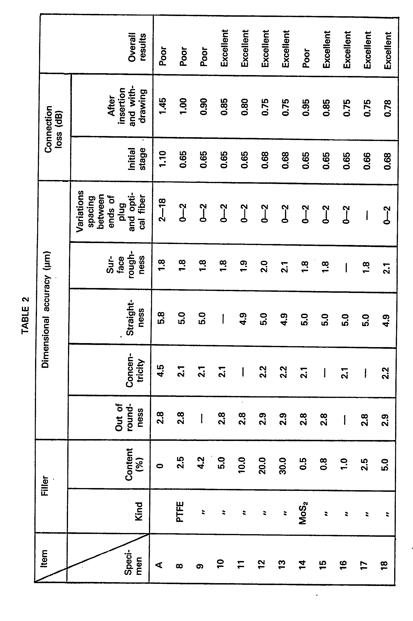
- As can be clearly seen in Table 2, no lubrication effects as desired could be achieved when PTFE was used as a lubricant unless over 5 wt% was added. However, if the content of PTFE added exceeded 30 wt%, the fluidity of the material was reduced when molding was carried out. Thus when PTFE is added, the amount should be in the range between 5 and 30 wt%.
- When MoS2 is used as a filler, the content in the range between 1 and 5% is optimum.
- In producing the
plug 6, an epoxy resin was used as synthetic resin and glass beads of silica glass of a mean particle size of 10 µm were used as a filler Tests were conducted in the same manner as described by referring to Example 1. - The results of the tests are shown in Table 3.

- As can be seen in Table 3, when the
plug 6 is produced by using an epoxy resin, it is desirable that glass beads be added as a filler in 30―80 wt%. When the glass beads exceeded 81 wt% in amount, the fluidity of the resin was reduced at the time of molding operation, resulting in lowered molding characteristic of the resin. - It is believed that the need to use a large content of filler in combination with the use of an epoxy resin as a material for producing the
plug 6 is accounted for by the essential difference in nature between polycarbonate and epoxy resin and the difference in fluidity (viscosity) existing at the time of molding operation. - The amount of the lubricant necessary for application to compensate for insertion and withdrawing of the
plug 6 was the subject of study in the same manner as described by referring to example 1. - The specimens used in the tests consisted of an epoxy resin added with silica glass in 69 wt%, and the lubricants included PTFE, MoS2 and graphite.
- The results are shown in Table 4.

- As can be clearly seen in Table 4, it was possible to reduce the connection loss after insertion and withdrawing of the
plug 6 when a lubricant was used. The amount of the lubricant added is preferably in the range between 1 and 5 wt% for achieving best lubrication effects and obtaining optimum formability. - In order to minimize the connection loss, it is essential that the outer diameter D, (Fig. 4) of the
optical fiber 2 of theoptical fiber cable 1 and the inner diameter d, (Fig. 3) of theorifice 8 of theplug 6 and the outer diameter D2 (Fig. 3) of the forward end portion of theplug 6 and the inner diameter d2 (Fig. 5) of the throughhole 11 of thesleeve 10 be controlled. - First of all, in order to align the center axis of the
optical fiber 2 with the center axis of theorifice 8 of theplug 6, the inner diameter d, of theorifice 8 has only to be made equal to the outer diameter D, of theoptical fiber 2. However, if the inner diameter d, of theorifice 8 were equal to the outer diameter D, of theoptical fiber 2, difficulties would be experienced in passing theoptical fiber 2 through theorifice 8 and in addition no gaps would be formed between theorifice 8 andoptical fiber 2 for admitting the adhesive agent thereinto. Meanwhile if the diameter d, were larger than the outer diameter D, of theorifice 8, eccentricity of the axes of theorifice 8 and theconductor 2 would become great. To overcome these difficulties, the inner diameter d, of theorifice 8 should be larger than the outer diameter D, of theoptical fiber 2 by 1-2 µm. This facilitates insertion of theoptical fiber 2 in theorifice 8 and makes it possible to restrict the eccentricity of theorifice 8 andoptical conductor 2 to 0.5-1 pm, in addition to facilitating admission of the adhesive agent between theoptical fiber 2 andorifice 8 to achieve bonding between them. - The outer diameter D2 of the
plug 6 and the inner diameter d2 of thesleeve 10 are decided by the force exerted for inserting and withdrawing theplug 6 and the connection loss. For example, Fig. 6 shows the force for inserting and withdrawing theplug 6 with respect to thesleeve 10 in relation to the connection loss, it being assumed that the difference (D2-d2) between the outer diameter D2 of theplug 6 and the inner diameter d2 of the sleeve provides a clearance necessary for fitting theplug 6 in thesleeve 10. In Fig. 6 in which A represents the insertion and withdrawing force and B indicates the connection loss, theplug 6 and thesleeve 10 used in combination were molded of an epoxy resin added with 69% of filler. When the fitting clearance is in the region (-), it is indicated that theplug 6 is force fitted in thesleeve 10, and the insertion and withdrawing force is high while the connection loss is small. On the other hand, when the fitting clearance is in the region (+), it will be seen that although the insertion and withdrawing force is low the connection loss is great. - Fig. 7 shows the number of times the plug is inserted and withdrawn in relation to changes in the connection loss with respect to a connection loss of the initial stages. In Fig. 7, a represents the fitting clearance being -3 µm at initial stages, and b indicates the fitting clearance being -2 µm at initial stages. As can be clearly seen in Fig. 6, the greater the fitting clearance in the (-) region, the higher became the frictional force acting between the
plug 6 and thesleeve 10 when the former was inserted or withdrawn. This caused greater wear on the parts, so that the connection loss showed larger changes. - In view of the foregoing, it would be possible to keep the connection loss including the influences of insertion and withdrawing of the
plug 6 to a level below 1 dB if the fitting clearance of theplug 6 in thesleeve 10 were set in the range between -3 and +2 µm. - Fig. 8 shows the influences exerted by the combination of the
plug 6 and thesleeve 10 on connection losses. In Fig. 8, A1 represents thesleeve 10 formed of an epoxy resin and theplug 6 of polycarbonate and B1 represents theplug 6 andsleeve 10 both formed of an epoxy resin (the fitting clearance is 0 when the temperature is 22 degrees). As can be clearly seen in the figure, the influences of the temperature can be eliminated if the same material is used. Thus theplug 6 and thesleeve 10 are preferably formed of the same material. - An adhesive agent of low viscosity (below 20 poise) is used as an adhesive agent. By adding a filler to the adhesive agent, it is possible to reduce the eccentricity of the center axis of the
optical fiber 2 of theoptical fiber cable 1 with respect to the center axis of theorifice 8 of theplug 6. For example, alumina powder of an average particle size of 0.3 pm may be added as a filler in 40-60 wt% to the adhesive agent when d1=D1+1 µm. This gives a uniform distribution of the filler between theorifice 8 and theoptical fiber 2, so that the eccentricity of theoptical fiber 2 with respect to theorifice 8 can be reduced to a level below 0.2 pm at a maximum. The mean particle size of the filler is about 50-70% of the clearance between theorifice 8 and theoptical fiber 2. A suitable material should be selected for the filler. - Fig. 9 shows another embodiment of the invention wherein parts similar to those shown in Fig. 1 are designated by like reference characters. A glass tube 25 is attached to the
optical fiber 2 of theoptical fiber cable 1 and inserted in thebore 7 of theplug 6 where it is adhesively bonded to theplug pin 6 and theoptical fiber 2. - This construction lends the optical fiber connector according to the invention to applications in which the connector is installed in places of large variations in temperature where the connector is subjected to repeated heating and cooling, for a monitoring system for the piping or processing devices of chemical plants or a data transmission system built in the rolling mill of a steel making plant, for example.
- More specifically, when the
optical fiber connector 5 is subjected to repeated heating and cooling at a temperature of 100 degrees or thereabout, the difference in thermal expansion between theoptical fiber 2 of theoptical fiber cable 1 and theplug 6 and the adhesive agent causes peeling of the adhesive agent, and when the adhesive agent is pushed out of the forward end of theplug 6 by thermal expansion, theoptical fiber 2 is simultaneously pushed out. This reduces the reliability of theoptical fiber connector 5 used in transmission of information. - This disadvantage can be eliminated by using the glass tube 25, because the
optical fiber 2 is restrained by the glass tube 25 and prevented from sticking out of theplug 6 even if subjected to repeated heating and cooling.
Claims (9)
Applications Claiming Priority (4)
| Application Number | Priority Date | Filing Date | Title |
|---|---|---|---|
| JP157583/80 | 1980-11-11 | ||
| JP15758380A JPS5781224A (en) | 1980-11-11 | 1980-11-11 | Production of plastic optical connector |
| JP81012/81 | 1981-05-29 | ||
| JP8101281A JPS57196208A (en) | 1981-05-29 | 1981-05-29 | Plastic composite containing filler for molding optical connector or the like and precise molded goods using this composite |
Publications (3)
| Publication Number | Publication Date |
|---|---|
| EP0052014A2 EP0052014A2 (en) | 1982-05-19 |
| EP0052014A3 EP0052014A3 (en) | 1983-01-19 |
| EP0052014B1 true EP0052014B1 (en) | 1985-08-21 |
Family
ID=26422063
Family Applications (1)
| Application Number | Title | Priority Date | Filing Date |
|---|---|---|---|
| EP81305337A Expired EP0052014B1 (en) | 1980-11-11 | 1981-11-10 | Optical fiber connector and method of producing same |
Country Status (3)
| Country | Link |
|---|---|
| US (1) | US4484796A (en) |
| EP (1) | EP0052014B1 (en) |
| DE (1) | DE3171940D1 (en) |
Families Citing this family (78)
| Publication number | Priority date | Publication date | Assignee | Title |
|---|---|---|---|---|
| ATE40011T1 (en) * | 1982-11-26 | 1989-01-15 | British Telecomm | CONNECTORS. |
| US4850670A (en) * | 1983-08-29 | 1989-07-25 | American Telephone And Telegraph Company, At&T Bell Laboratories | Optical fiber connector comprising drawn glass tubes |
| US4934785A (en) * | 1983-08-29 | 1990-06-19 | American Telephone And Telegraph Company | Optical fiber connector |
| US4896938A (en) * | 1983-08-29 | 1990-01-30 | American Telephone And Telegraph Company, At&T Bell Laboratories | Optical fiber connector comprising glass tubes |
| SE8403740L (en) * | 1984-07-17 | 1986-01-18 | Stratos Ab | SET FOR FIXING AN OPTICAL FIBER IN A CONNECTOR AND A PAUSE MANUFACTURED CONNECTOR |
| US4830922A (en) * | 1986-02-28 | 1989-05-16 | Sparrowhawk Bryan L | Removable controlled thickness conformal coating |
| CH681329A5 (en) * | 1991-02-11 | 1993-02-26 | Diamond Sa | |
| EP0704486B1 (en) * | 1994-03-18 | 2005-09-21 | Mitsubishi Denki Kabushiki Kaisha | Resin composition for molding precision parts, and sleeve and ferrule produced therefrom |
| US5724466A (en) * | 1995-11-16 | 1998-03-03 | Raytheon E-Systems | Ruggedized blind mating connector for optical fibers |
| US5633963A (en) * | 1995-12-12 | 1997-05-27 | Raytheon Company | Optical rotary joint for single and multimode fibers |
| US6676300B2 (en) | 2001-01-25 | 2004-01-13 | Sumitomo Electric Industries, Ltd. | Ferrule for optical connector and making method thereof |
| US6964525B2 (en) | 2001-01-25 | 2005-11-15 | Sumitomo Electric Industries, Ltd. | Optical connector and backplane assembly |
| EP1369720B1 (en) * | 2001-02-28 | 2007-09-19 | Sumitomo Electric Industries, Ltd. | Ferrule for optical connector and method of manufacturing the ferrule |
| JP3735049B2 (en) * | 2001-05-16 | 2006-01-11 | 古河電気工業株式会社 | Optical module and adhesive applied to the optical module |
| US7052187B2 (en) | 2002-02-28 | 2006-05-30 | Sumitomo Electric Industries, Ltd. | Optical connector ferrule, optical connector and making method for them |
| US7156559B2 (en) * | 2003-04-21 | 2007-01-02 | The Johns Hopkins University | High temperature light guide |
| US8157589B2 (en) | 2004-11-24 | 2012-04-17 | John Mezzalingua Associates, Inc. | Connector having a conductively coated member and method of use thereof |
| US20060110977A1 (en) | 2004-11-24 | 2006-05-25 | Roger Matthews | Connector having conductive member and method of use thereof |
| US7114990B2 (en) | 2005-01-25 | 2006-10-03 | Corning Gilbert Incorporated | Coaxial cable connector with grounding member |
| JP4915243B2 (en) * | 2007-01-15 | 2012-04-11 | 日立電線株式会社 | Optical connector |
| US8075337B2 (en) | 2008-09-30 | 2011-12-13 | Belden Inc. | Cable connector |
| US8025518B2 (en) | 2009-02-24 | 2011-09-27 | Corning Gilbert Inc. | Coaxial connector with dual-grip nut |
| US8029315B2 (en) | 2009-04-01 | 2011-10-04 | John Mezzalingua Associates, Inc. | Coaxial cable connector with improved physical and RF sealing |
| US7824216B2 (en) | 2009-04-02 | 2010-11-02 | John Mezzalingua Associates, Inc. | Coaxial cable continuity connector |
| US7892005B2 (en) | 2009-05-19 | 2011-02-22 | John Mezzalingua Associates, Inc. | Click-tight coaxial cable continuity connector |
| US9017101B2 (en) | 2011-03-30 | 2015-04-28 | Ppc Broadband, Inc. | Continuity maintaining biasing member |
| US8573996B2 (en) | 2009-05-22 | 2013-11-05 | Ppc Broadband, Inc. | Coaxial cable connector having electrical continuity member |
| US8287320B2 (en) | 2009-05-22 | 2012-10-16 | John Mezzalingua Associates, Inc. | Coaxial cable connector having electrical continuity member |
| US8444445B2 (en) | 2009-05-22 | 2013-05-21 | Ppc Broadband, Inc. | Coaxial cable connector having electrical continuity member |
| US9570845B2 (en) | 2009-05-22 | 2017-02-14 | Ppc Broadband, Inc. | Connector having a continuity member operable in a radial direction |
| US8272893B2 (en) | 2009-11-16 | 2012-09-25 | Corning Gilbert Inc. | Integrally conductive and shielded coaxial cable connector |
| TWI549386B (en) | 2010-04-13 | 2016-09-11 | 康寧吉伯特公司 | Coaxial connector with inhibited ingress and improved grounding |
| US8152551B2 (en) | 2010-07-22 | 2012-04-10 | John Mezzalingua Associates, Inc. | Port seizing cable connector nut and assembly |
| US8079860B1 (en) | 2010-07-22 | 2011-12-20 | John Mezzalingua Associates, Inc. | Cable connector having threaded locking collet and nut |
| US8113879B1 (en) | 2010-07-27 | 2012-02-14 | John Mezzalingua Associates, Inc. | One-piece compression connector body for coaxial cable connector |
| US8888526B2 (en) | 2010-08-10 | 2014-11-18 | Corning Gilbert, Inc. | Coaxial cable connector with radio frequency interference and grounding shield |
| US8167636B1 (en) | 2010-10-15 | 2012-05-01 | John Mezzalingua Associates, Inc. | Connector having a continuity member |
| US8323053B2 (en) | 2010-10-18 | 2012-12-04 | John Mezzalingua Associates, Inc. | Connector having a constant contact nut |
| US8075338B1 (en) | 2010-10-18 | 2011-12-13 | John Mezzalingua Associates, Inc. | Connector having a constant contact post |
| US8167635B1 (en) | 2010-10-18 | 2012-05-01 | John Mezzalingua Associates, Inc. | Dielectric sealing member and method of use thereof |
| US8167646B1 (en) | 2010-10-18 | 2012-05-01 | John Mezzalingua Associates, Inc. | Connector having electrical continuity about an inner dielectric and method of use thereof |
| TWI558022B (en) | 2010-10-27 | 2016-11-11 | 康寧吉伯特公司 | Push-on cable connector with a coupler and retention and release mechanism |
| US8337229B2 (en) | 2010-11-11 | 2012-12-25 | John Mezzalingua Associates, Inc. | Connector having a nut-body continuity element and method of use thereof |
| US8414322B2 (en) | 2010-12-14 | 2013-04-09 | Ppc Broadband, Inc. | Push-on CATV port terminator |
| US8398421B2 (en) | 2011-02-01 | 2013-03-19 | John Mezzalingua Associates, Inc. | Connector having a dielectric seal and method of use thereof |
| US8157588B1 (en) | 2011-02-08 | 2012-04-17 | Belden Inc. | Cable connector with biasing element |
| US8342879B2 (en) | 2011-03-25 | 2013-01-01 | John Mezzalingua Associates, Inc. | Coaxial cable connector |
| US8465322B2 (en) | 2011-03-25 | 2013-06-18 | Ppc Broadband, Inc. | Coaxial cable connector |
| US8366481B2 (en) | 2011-03-30 | 2013-02-05 | John Mezzalingua Associates, Inc. | Continuity maintaining biasing member |
| US8388377B2 (en) | 2011-04-01 | 2013-03-05 | John Mezzalingua Associates, Inc. | Slide actuated coaxial cable connector |
| US8348697B2 (en) | 2011-04-22 | 2013-01-08 | John Mezzalingua Associates, Inc. | Coaxial cable connector having slotted post member |
| US9711917B2 (en) | 2011-05-26 | 2017-07-18 | Ppc Broadband, Inc. | Band spring continuity member for coaxial cable connector |
| WO2012162431A2 (en) | 2011-05-26 | 2012-11-29 | Belden Inc. | Coaxial cable connector with conductive seal |
| US8758050B2 (en) | 2011-06-10 | 2014-06-24 | Hiscock & Barclay LLP | Connector having a coupling member for locking onto a port and maintaining electrical continuity |
| US8591244B2 (en) | 2011-07-08 | 2013-11-26 | Ppc Broadband, Inc. | Cable connector |
| US9190744B2 (en) | 2011-09-14 | 2015-11-17 | Corning Optical Communications Rf Llc | Coaxial cable connector with radio frequency interference and grounding shield |
| US20130072057A1 (en) | 2011-09-15 | 2013-03-21 | Donald Andrew Burris | Coaxial cable connector with integral radio frequency interference and grounding shield |
| US9147955B2 (en) | 2011-11-02 | 2015-09-29 | Ppc Broadband, Inc. | Continuity providing port |
| US9136654B2 (en) | 2012-01-05 | 2015-09-15 | Corning Gilbert, Inc. | Quick mount connector for a coaxial cable |
| US9407016B2 (en) | 2012-02-22 | 2016-08-02 | Corning Optical Communications Rf Llc | Coaxial cable connector with integral continuity contacting portion |
| CN103708590A (en) * | 2012-09-29 | 2014-04-09 | 埃科莱布美国股份有限公司 | Water treatment dosing optimizing system, water treatment system, and method of water treatment dosing optimizing system |
| CN103712927B (en) * | 2012-09-29 | 2016-12-21 | 埃科莱布美国股份有限公司 | Detecting system and method and water treatment system and method |
| US9287659B2 (en) | 2012-10-16 | 2016-03-15 | Corning Optical Communications Rf Llc | Coaxial cable connector with integral RFI protection |
| US9147963B2 (en) | 2012-11-29 | 2015-09-29 | Corning Gilbert Inc. | Hardline coaxial connector with a locking ferrule |
| US9153911B2 (en) | 2013-02-19 | 2015-10-06 | Corning Gilbert Inc. | Coaxial cable continuity connector |
| US9172154B2 (en) | 2013-03-15 | 2015-10-27 | Corning Gilbert Inc. | Coaxial cable connector with integral RFI protection |
| US9130281B2 (en) | 2013-04-17 | 2015-09-08 | Ppc Broadband, Inc. | Post assembly for coaxial cable connectors |
| US10290958B2 (en) | 2013-04-29 | 2019-05-14 | Corning Optical Communications Rf Llc | Coaxial cable connector with integral RFI protection and biasing ring |
| CN105284015B (en) | 2013-05-20 | 2019-03-08 | 康宁光电通信Rf有限责任公司 | Coaxial Cable Connectors with Integral RFI Protection |
| US9548557B2 (en) | 2013-06-26 | 2017-01-17 | Corning Optical Communications LLC | Connector assemblies and methods of manufacture |
| US9048599B2 (en) | 2013-10-28 | 2015-06-02 | Corning Gilbert Inc. | Coaxial cable connector having a gripping member with a notch and disposed inside a shell |
| WO2016073309A1 (en) | 2014-11-03 | 2016-05-12 | Corning Optical Communications Rf Llc | Coaxial cable connector with integral rfi protection |
| US9590287B2 (en) | 2015-02-20 | 2017-03-07 | Corning Optical Communications Rf Llc | Surge protected coaxial termination |
| US10033122B2 (en) | 2015-02-20 | 2018-07-24 | Corning Optical Communications Rf Llc | Cable or conduit connector with jacket retention feature |
| US10211547B2 (en) | 2015-09-03 | 2019-02-19 | Corning Optical Communications Rf Llc | Coaxial cable connector |
| US9525220B1 (en) | 2015-11-25 | 2016-12-20 | Corning Optical Communications LLC | Coaxial cable connector |
| US12034264B2 (en) | 2021-03-31 | 2024-07-09 | Corning Optical Communications Rf Llc | Coaxial cable connector assemblies with outer conductor engagement features and methods for using the same |
| CN115466108B (en) * | 2021-12-15 | 2023-08-15 | 中国海洋石油集团有限公司 | Underwater optical fiber contact pin material with self-lubricating performance and preparation method thereof |
Family Cites Families (14)
| Publication number | Priority date | Publication date | Assignee | Title |
|---|---|---|---|---|
| DE2456151A1 (en) * | 1974-11-27 | 1976-08-12 | Siemens Ag | Plug-in connector between at least two optical fibres - end of each glass fibre fastened inside capillary tube |
| GB1480444A (en) * | 1975-05-06 | 1977-07-20 | Standard Telephones Cables Ltd | Termination of optical fibres |
| CA1094369A (en) * | 1975-11-11 | 1981-01-27 | Peter K. Runge | Optical fiber connector and method of making |
| US4173389A (en) * | 1977-09-28 | 1979-11-06 | Bell Telephone Laboratories, Incorporated | Molded optical fiber connector |
| JPS5455451A (en) * | 1977-10-12 | 1979-05-02 | Nippon Telegr & Teleph Corp <Ntt> | Production of connector plug for optical fibers |
| IT1099929B (en) * | 1977-10-25 | 1985-09-28 | Amp Inc | ASSEMBLY OF CONNECTOR FOR OPTICAL FIBERS |
| DE2753298C2 (en) * | 1977-11-30 | 1985-06-20 | ANT Nachrichtentechnik GmbH, 7150 Backnang | Connector for connecting fiber optic cables |
| JPS54157635A (en) * | 1978-06-01 | 1979-12-12 | Sumitomo Electric Ind Ltd | Optical connector |
| US4362356A (en) * | 1978-09-11 | 1982-12-07 | Amp Incorporated | Concentric optic termination utilizing a fixture |
| CA1135097A (en) * | 1978-09-11 | 1982-11-09 | Amp Incorporated | Method of terminating optical fibres |
| FR2436406A1 (en) * | 1978-09-12 | 1980-04-11 | Socapex | CONNECTOR FOR OPTICAL FIBER, CENTERING DEVICE AND METHOD FOR MANUFACTURING SAID CONNECTOR |
| JPS55120008A (en) * | 1979-03-08 | 1980-09-16 | Fujitsu Ltd | Forming method of plastic connector for optical fiber |
| JPS5689709A (en) * | 1979-12-21 | 1981-07-21 | Nec Corp | Plastic plug for optical fiber and connector using it |
| US4365037A (en) * | 1980-07-18 | 1982-12-21 | Dainippon Ink & Chemicals, Inc. | Glass fiber-reinforced polyarylene sulfide resin composition |
-
1981
- 1981-11-10 US US06/319,986 patent/US4484796A/en not_active Expired - Fee Related
- 1981-11-10 DE DE8181305337T patent/DE3171940D1/en not_active Expired
- 1981-11-10 EP EP81305337A patent/EP0052014B1/en not_active Expired
Non-Patent Citations (1)
| Title |
|---|
| REVIEW OF ELECTRICAL COMMUNICATIONS LABORATORIES, vol. 27, nos. 11 to 12, 1979, Tokyo, N. SUZUKI et al. "Demountable connectors for optical fiber transmission equipment", pages 999 to 1009 * |
Also Published As
| Publication number | Publication date |
|---|---|
| US4484796A (en) | 1984-11-27 |
| EP0052014A3 (en) | 1983-01-19 |
| EP0052014A2 (en) | 1982-05-19 |
| DE3171940D1 (en) | 1985-09-26 |
Similar Documents
| Publication | Publication Date | Title |
|---|---|---|
| EP0052014B1 (en) | Optical fiber connector and method of producing same | |
| US4173389A (en) | Molded optical fiber connector | |
| US4330171A (en) | Optical-fiber connector, centering device and method of manufacture of said connector | |
| JP6401316B2 (en) | Optical fiber connector ferrule with fiber clamp open groove | |
| DE2648652C3 (en) | Optical fiber connector | |
| US4133601A (en) | Optical fibers bundle positioning ferrule | |
| EP0110140B1 (en) | Method and apparatus for forming an optical connector | |
| US5887099A (en) | Fiber optic connector with improved return loss performance | |
| EP0661565B1 (en) | Optical semiconductor module and a method for fabricating the same | |
| US4479910A (en) | Method for production of optical fiber connectors | |
| CA1197121A (en) | Optical fibre connector end fitting, process for centring a fibre in the end fitting and device for performing this process | |
| EP0078927A1 (en) | Method of mounting a connector terminal on an optical fibre | |
| JP3764477B2 (en) | Injection molding optical ferrule and apparatus and process for its preparation | |
| DE69330563T2 (en) | Coupling of planar optical waveguides and optical fibers with low back reflection | |
| US4429949A (en) | Connector for optical fibers wherein individual fiber is centered by a plurality of balls | |
| US4424174A (en) | Fabrication of optical connectors | |
| US6994477B2 (en) | Ferrule for optical connector, metal article having a through-hole and manufacturing method therefor | |
| DE2803670A1 (en) | CONNECTOR FOR LIGHT GUIDE | |
| DE2906104C3 (en) | Device for coupling two optical fibers | |
| US20250116825A1 (en) | Method for making a low-loss fiber optic connector | |
| JPS635732B2 (en) | ||
| US4200136A (en) | Method for making an optical waveguide coating die | |
| CA1270136A (en) | Method of centering and fixing a light-conducting fibre in a light conductor terminal member, a light conductor terminal member produced by that method, and apparatus for carrying out the method | |
| CA1270135A (en) | Methods of and apparatus for adjusting optical fiber connector components and products produced thereby | |
| Johnson et al. | Precision molded plastic ferrules for single-mode optical fibers |
Legal Events
| Date | Code | Title | Description |
|---|---|---|---|
| PUAI | Public reference made under article 153(3) epc to a published international application that has entered the european phase |
Free format text: ORIGINAL CODE: 0009012 |
|
| AK | Designated contracting states |
Designated state(s): DE FR GB |
|
| PUAL | Search report despatched |
Free format text: ORIGINAL CODE: 0009013 |
|
| AK | Designated contracting states |
Designated state(s): DE FR GB |
|
| 17P | Request for examination filed |
Effective date: 19830528 |
|
| GRAA | (expected) grant |
Free format text: ORIGINAL CODE: 0009210 |
|
| AK | Designated contracting states |
Designated state(s): DE FR GB |
|
| REF | Corresponds to: |
Ref document number: 3171940 Country of ref document: DE Date of ref document: 19850926 |
|
| ET | Fr: translation filed | ||
| PLBE | No opposition filed within time limit |
Free format text: ORIGINAL CODE: 0009261 |
|
| STAA | Information on the status of an ep patent application or granted ep patent |
Free format text: STATUS: NO OPPOSITION FILED WITHIN TIME LIMIT |
|
| 26N | No opposition filed | ||
| PG25 | Lapsed in a contracting state [announced via postgrant information from national office to epo] |
Ref country code: GB Effective date: 19881110 |
|
| GBPC | Gb: european patent ceased through non-payment of renewal fee | ||
| PG25 | Lapsed in a contracting state [announced via postgrant information from national office to epo] |
Ref country code: FR Free format text: LAPSE BECAUSE OF NON-PAYMENT OF DUE FEES Effective date: 19890731 |
|
| PG25 | Lapsed in a contracting state [announced via postgrant information from national office to epo] |
Ref country code: DE Effective date: 19890801 |
|
| REG | Reference to a national code |
Ref country code: FR Ref legal event code: ST |