EP0052174A1 - Filterpresse - Google Patents
Filterpresse Download PDFInfo
- Publication number
- EP0052174A1 EP0052174A1 EP80870048A EP80870048A EP0052174A1 EP 0052174 A1 EP0052174 A1 EP 0052174A1 EP 80870048 A EP80870048 A EP 80870048A EP 80870048 A EP80870048 A EP 80870048A EP 0052174 A1 EP0052174 A1 EP 0052174A1
- Authority
- EP
- European Patent Office
- Prior art keywords
- frames
- filter
- frame
- plates
- cakes
- Prior art date
- Legal status (The legal status is an assumption and is not a legal conclusion. Google has not performed a legal analysis and makes no representation as to the accuracy of the status listed.)
- Granted
Links
Images
Classifications
-
- B—PERFORMING OPERATIONS; TRANSPORTING
- B01—PHYSICAL OR CHEMICAL PROCESSES OR APPARATUS IN GENERAL
- B01D—SEPARATION
- B01D25/00—Filters formed by clamping together several filtering elements or parts of such elements
- B01D25/12—Filter presses, i.e. of the plate or plate and frame type
- B01D25/172—Plate spreading means
-
- B—PERFORMING OPERATIONS; TRANSPORTING
- B01—PHYSICAL OR CHEMICAL PROCESSES OR APPARATUS IN GENERAL
- B01D—SEPARATION
- B01D25/00—Filters formed by clamping together several filtering elements or parts of such elements
- B01D25/32—Removal of the filter cakes
- B01D25/322—Removal of the filter cakes specially for chamber filter presses
Definitions
- the invention relates to a filter press for the separation of the solid phase and the liquid phase of a slurry to be filtered.
- It consists of trays and frames, a filter cloth being attached to each side of a tray.
- each chamber formed by two adjoining trays is divided by a metal plate, on which a cake would stick on each side.
- the trays are then separated by at least the thickness of the cakes.
- the plates are then lowered.
- the filter fabrics are not washed.
- the plates (6) are suspended by rollers (5) which roll on cross members not referenced.
- the frames are grouped in pairs (11a-11b) and p IRES (12a-12b). Each pair of the first group is carried from below, by rollers (21) rolling in sleepers (20). Each pair of the second group is carried from above by rollers (21) rolling in sleepers (19).
- the frames are lowered and raised by acting on the crosspieces (19) first, then on the crosspieces (20) by two separate commands, i.e. (15-16-17-18 and 13 a) for the first and (same n ° + 13b) for the second.
- This thin layer has a high specific resistance which paralyzes the subsequent filtration.
- a first objective of the invention below is to remove the frames from the filter, but all at the same time, thus forming two lines with that of the plates, remaining in the filter, and retaining the essential parallelism between the frames and with the trays.
- a second objective of the invention is to push automatically, all the cakes at the same time, out of the fully extended frames, the pushing taking place in a vertical plane and being carried out all at once, over the entire surface of each cake.
- a third objective of the invention is to wash fabrics and contact surfaces, to unclog them.
- a fourth objective is to avoid great mechanical complexity.
- a fifth objective is to fully automate the filter, to remove labor for strenuous work and increase its efficiency.
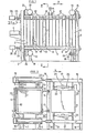
- the filter press comprises a first fixed resistor plate 1 extra gold - ted by fixed feet 2, a mobile 3 plate in the directions of arrow X, by a mechanical or hydraulic jack 4 double effect and a second plate 5 fixed resistance supported by fixed feet 6, in opposition with parts 1 and 2 above.
- Tie rods 7 keep feet 2 and 6 at a distance and contribute to the resistance of the assembly, to the pressure in the filter during filtration.
- tie rods 7 extend parallel to the axis Ion gitudinal filter but are located, unlike au t res filters above and below the plates 1 and 5 to retain the free sides of the filter, for reasons discussed far.
- a frame 10 Between these plates come successively a frame 10, a plate with two filtering faces 11, a frame 10, etc. On the filtering faces are fixed by face a sheet of filtering fabric (not shown).
- a frame is inserted between two adjacent trays.
- the plates 11 are alone suspended from the upper tie rods 7, by closed bearings 12 sliding on the said tie rods and such that the plates are held in the vertical plane, without being able to tilt when the plates are moved in the longitudinal axis of the filter.
- the frames 10 carry on one side closed pads 13 which can slide on bars 14 attached by each end to movable uprights 15 themselves carrying sliding blocks 16 at their ends, capable of sliding in sleepers 17 fixedly supported on feet 18.
- Pneumatic or mechanical cylinders 19 act on the sliding blocks 16 to push or pull them with the frames 10 respectively to extract all the frames from the filter press or to return all of these frames to the filter press.
- the frames After filtration and the opening of the filter which distances the frames 10 and the plates 11 by the jack 4, the frames are pushed out of the filter, in the direction of the arrow Y, by the jacks 19, the frames come in front of cake unloading plates 21, having dimensions corresponding to the internal dimensions of the frames 10.
- unloading plates are firmly fixed by fasteners 22 to parallel bars 23 capable of sliding in guides (not shown) of fixed posts 24.
- the bars 23 are fixed to crosspieces 25 which can be pushed or retracted over a corresponding distance to the thickness of the frame 10, by one or more double-acting cylinders 26.
- a vibrator 23a is fixed on one or more bars 23. Its vibration is reflected in the plates 21, for the total discharge of the cakes, in a vertical plane.
- each frame 10 On the left side of each frame 10 (considering Fig. 2) or on the side of the frames 10 which will be adjacent to the filter, when these frames are removed from the filter is fixed a perforated pipe 20 connected by a hose and a manifold (not shown) to a supply of fabric washing liquid, which will be sprayed on the fabrics by the perforations of the pipe 20 when the frames 10 are retracted in the filter, after the discharge of the cakes, the retraction being done in the direction opposite to that of arrow Y.
- a perforated pipe 20 connected by a hose and a manifold (not shown) to a supply of fabric washing liquid, which will be sprayed on the fabrics by the perforations of the pipe 20 when the frames 10 are retracted in the filter, after the discharge of the cakes, the retraction being done in the direction opposite to that of arrow Y.
- two (or more) sprays 20a adjustable and fixed above each tray projected against the internal faces of two adjacent frames in the tray, j and thin and vertical contact surfaces washing liquid frames.
- other sprayers 20 a can be attached under each tray and act additionally from bottom to top, under the same conditions and during the retraction of the frames.
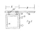
- the plates 8 and the plurality 11 carry a fork 27 (Fig.3) for example on their upper side, cooperating with lugs 28 carried by each frame 10 and being in the space 29 limited by the legs 27 'of fork 27 carried by the plate 11 between two neighboring frames 10.
- the forks 27 attached to the movable plates 8 and 11 move until a leg 27 t of the fork 27 comes into contact with a lug of the frame 10 successively, which causes the trays and the frames to move and are distanoed by the desired value in and according to the space 29.
- the frames 10 can then be removed from the filter, as indicated above, in the direction of the arrow Y towards the discharge position of the filtered cakes.
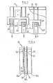
- each frame 10 may consist of three parts 10 a, 10 b, 10 c attached and comprising two elastic elastic sheets 30 and 31 respectively between parts 10 a and 10 c and between parts 10 c and 10 b.
- the slurry to be filtered is in this case supplied by the two inlets 32 of the interior compartments, while a pressurized fluid can be introduced into the interior compartment, through the inlet 33.
- Fig.4 shows the two possibilities, on one side the elastic sheet without rigid plate, on the other side the elastic sheet with a rigid plate partially displaced.
- the pins 28 fixed to the frames are each shaped with a head 28 'trapped and sliding in profiles 36, supported and placed parallel to the frames and above them.
- the profiles 3 6 overhang the frames of either the length A and also the outlet travel of the filter frames, or the length B. In this case, the profiles are moved and spaced with the frames by the parts 27-28
- the profiles have only length B.
- the outlet displacement of the frames out of the filter causes the heads 28 ′ of the pins 28 to enter the profiles 36, which are fixed in this case; which adds to the action of the fasteners 13 and bars 14 for supporting and guiding the frames in lateral displacement.
- the different stages of working the filter i.e. filtration, washing the cakes, compressing the cakes, opening the filter, transferring the frames out of the filter, unloading the cakes, shrinking the frames in the filter, washing of fabrics and contact surfaces of the frames, closing of the filter, etc., are automatically programmed.
- a programmer includes two kinds of adjustable cams: main cams and secondary cams.
- the main cams are used for each operation to be performed by the filter; they are only used if the operation is done in a fixed time, their notch being adjusted for this.
- the duration of which must vary according to the momentary filtration parameters is completed by a secondary cam operating in the notch of the main cam.
- the secondary cam stops the programmer, during the time set by a timer connected to the secondary cam, then starts the programmer to perfect the time set by the main cam.
- the setting of the duration of an operation is completely independent of the other settings to be made, the case is important for filtration.
Landscapes
- Chemical & Material Sciences (AREA)
- Chemical Kinetics & Catalysis (AREA)
- Filtration Of Liquid (AREA)
- Fluid-Pressure Circuits (AREA)
- Dry Shavers And Clippers (AREA)
Priority Applications (3)
| Application Number | Priority Date | Filing Date | Title |
|---|---|---|---|
| AT80870048T ATE9442T1 (de) | 1980-11-18 | 1980-11-18 | Filterpresse. |
| EP80870048A EP0052174B1 (de) | 1980-11-18 | 1980-11-18 | Filterpresse |
| DE8080870048T DE3069232D1 (en) | 1980-11-18 | 1980-11-18 | Filter press |
Applications Claiming Priority (1)
| Application Number | Priority Date | Filing Date | Title |
|---|---|---|---|
| EP80870048A EP0052174B1 (de) | 1980-11-18 | 1980-11-18 | Filterpresse |
Publications (2)
| Publication Number | Publication Date |
|---|---|
| EP0052174A1 true EP0052174A1 (de) | 1982-05-26 |
| EP0052174B1 EP0052174B1 (de) | 1984-09-19 |
Family
ID=8187496
Family Applications (1)
| Application Number | Title | Priority Date | Filing Date |
|---|---|---|---|
| EP80870048A Expired EP0052174B1 (de) | 1980-11-18 | 1980-11-18 | Filterpresse |
Country Status (3)
| Country | Link |
|---|---|
| EP (1) | EP0052174B1 (de) |
| AT (1) | ATE9442T1 (de) |
| DE (1) | DE3069232D1 (de) |
Cited By (4)
| Publication number | Priority date | Publication date | Assignee | Title |
|---|---|---|---|---|
| FR2582538A1 (fr) * | 1985-06-04 | 1986-12-05 | Parmentier Alfred H | Filtres-presses |
| US4816147A (en) * | 1985-07-02 | 1989-03-28 | Brasserie Piedboeuf | Filter press-type filtering apparatus using rigid filter element |
| US4931177A (en) * | 1985-06-04 | 1990-06-05 | Parmentier Alfred H | Composite plate for filter-presses |
| CN114028847A (zh) * | 2021-11-24 | 2022-02-11 | 河南浩多顺节能环保科技有限公司 | 一种环保型多功能污水处理设备 |
Citations (1)
| Publication number | Priority date | Publication date | Assignee | Title |
|---|---|---|---|---|
| DE501079C (de) * | 1927-03-10 | 1930-06-28 | Capra Filter Press Corp | Filterpresse |
Family Cites Families (2)
| Publication number | Priority date | Publication date | Assignee | Title |
|---|---|---|---|---|
| DK113570B (da) * | 1965-01-20 | 1969-04-08 | Smidth & Co As F L | Udkastemekanisme for slamkager fra trykslamfilter. |
| US3647082A (en) * | 1968-11-02 | 1972-03-07 | Ishigaki Mech Ind | Filter press |
-
1980
- 1980-11-18 DE DE8080870048T patent/DE3069232D1/de not_active Expired
- 1980-11-18 EP EP80870048A patent/EP0052174B1/de not_active Expired
- 1980-11-18 AT AT80870048T patent/ATE9442T1/de not_active IP Right Cessation
Patent Citations (1)
| Publication number | Priority date | Publication date | Assignee | Title |
|---|---|---|---|---|
| DE501079C (de) * | 1927-03-10 | 1930-06-28 | Capra Filter Press Corp | Filterpresse |
Cited By (5)
| Publication number | Priority date | Publication date | Assignee | Title |
|---|---|---|---|---|
| FR2582538A1 (fr) * | 1985-06-04 | 1986-12-05 | Parmentier Alfred H | Filtres-presses |
| US4931177A (en) * | 1985-06-04 | 1990-06-05 | Parmentier Alfred H | Composite plate for filter-presses |
| US4816147A (en) * | 1985-07-02 | 1989-03-28 | Brasserie Piedboeuf | Filter press-type filtering apparatus using rigid filter element |
| CN114028847A (zh) * | 2021-11-24 | 2022-02-11 | 河南浩多顺节能环保科技有限公司 | 一种环保型多功能污水处理设备 |
| CN114028847B (zh) * | 2021-11-24 | 2022-09-16 | 河南浩多顺节能环保科技有限公司 | 一种环保型多功能污水处理设备 |
Also Published As
| Publication number | Publication date |
|---|---|
| ATE9442T1 (de) | 1984-10-15 |
| EP0052174B1 (de) | 1984-09-19 |
| DE3069232D1 (en) | 1984-10-25 |
Similar Documents
| Publication | Publication Date | Title |
|---|---|---|
| EP2692403B1 (de) | Abstreifervorrichtung zum entladen eines filterkuchens auf der filterplatte eines druckfilters | |
| CA1064766A (fr) | Procede et appareil de filtration continue d'une masse impregnee de liquide | |
| BE1005832A5 (fr) | Procede et appareillage de thermoformage et d'extraction d'objets creux munis d'un fond a partir d'une bande de matiere thermoplastique. | |
| WO2001074182A1 (fr) | Pressoir | |
| FR2473405A1 (fr) | Dispositif de moulage a centrage de noyaux bloques interieurement | |
| FR2490625A1 (fr) | Appareil de filtration et de sechage pour boues et analogues | |
| FR2536432A1 (fr) | Procede pour la fabrication d'etoffes non tissees portant des motifs en creux ou en relief, et etoffes non tissees ainsi obtenues | |
| EP0052174A1 (de) | Filterpresse | |
| DE1954490C3 (de) | Filterpresse | |
| EP0117159B1 (de) | Filterpresse mit Trennungsmittel für Schlamm | |
| FI78843C (fi) | Foerfarande foer rengoering av filtertyget i ett kammarfilter samt kammarfilter enligt foerfarandet. | |
| EP1066142B1 (de) | Einrichtung zur herstellung von latexgegenständen, wie beispielweise kissen | |
| US4377479A (en) | Vacuum belt filter | |
| EP0207555A2 (de) | Filteranlage | |
| FR2489210A1 (fr) | Extracteur de liquide | |
| EP0341098A1 (de) | Pneumatische Obstpresse | |
| FR2805199A1 (fr) | Procede d'extraction de liquide d'un materiau cellulaire, et dispositifs de mise en oeuvre dudit procede | |
| CN119680278B (zh) | 一种豆制品加工浆料过滤装置及过滤工艺 | |
| JPS6349197Y2 (de) | ||
| CN109124287B (zh) | 一种苹果取芯榨汁机 | |
| CN221309851U (zh) | 一种核桃油分离提纯器 | |
| FR2543449A1 (fr) | Filtre-presse a debatissage automatique | |
| JPS6349199Y2 (de) | ||
| JPS6366191B2 (de) | ||
| FR2679108A1 (fr) | Perfectionnements aux machines a fabriquer les calissons ou autres produits moules similaires. |
Legal Events
| Date | Code | Title | Description |
|---|---|---|---|
| PUAI | Public reference made under article 153(3) epc to a published international application that has entered the european phase |
Free format text: ORIGINAL CODE: 0009012 |
|
| AK | Designated contracting states |
Designated state(s): AT BE CH DE FR GB IT NL SE |
|
| 17P | Request for examination filed |
Effective date: 19821112 |
|
| GRAA | (expected) grant |
Free format text: ORIGINAL CODE: 0009210 |
|
| AK | Designated contracting states |
Designated state(s): AT BE CH DE FR GB IT LI NL SE |
|
| PG25 | Lapsed in a contracting state [announced via postgrant information from national office to epo] |
Ref country code: SE Effective date: 19840919 Ref country code: NL Effective date: 19840919 Ref country code: IT Free format text: LAPSE BECAUSE OF FAILURE TO SUBMIT A TRANSLATION OF THE DESCRIPTION OR TO PAY THE FEE WITHIN THE PRESCRIBED TIME-LIMIT;WARNING: LAPSES OF ITALIAN PATENTS WITH EFFECTIVE DATE BEFORE 2007 MAY HAVE OCCURRED AT ANY TIME BEFORE 2007. THE CORRECT EFFECTIVE DATE MAY BE DIFFERENT FROM THE ONE RECORDED. Effective date: 19840919 Ref country code: AT Effective date: 19840919 |
|
| REF | Corresponds to: |
Ref document number: 9442 Country of ref document: AT Date of ref document: 19841015 Kind code of ref document: T |
|
| REF | Corresponds to: |
Ref document number: 3069232 Country of ref document: DE Date of ref document: 19841025 |
|
| PGFP | Annual fee paid to national office [announced via postgrant information from national office to epo] |
Ref country code: DE Payment date: 19841115 Year of fee payment: 5 |
|
| PGFP | Annual fee paid to national office [announced via postgrant information from national office to epo] |
Ref country code: CH Payment date: 19841126 Year of fee payment: 5 |
|
| NLV1 | Nl: lapsed or annulled due to failure to fulfill the requirements of art. 29p and 29m of the patents act | ||
| PLBE | No opposition filed within time limit |
Free format text: ORIGINAL CODE: 0009261 |
|
| STAA | Information on the status of an ep patent application or granted ep patent |
Free format text: STATUS: NO OPPOSITION FILED WITHIN TIME LIMIT |
|
| 26N | No opposition filed | ||
| PG25 | Lapsed in a contracting state [announced via postgrant information from national office to epo] |
Ref country code: LI Effective date: 19861130 Ref country code: CH Effective date: 19861130 |
|
| REG | Reference to a national code |
Ref country code: CH Ref legal event code: PL |
|
| PG25 | Lapsed in a contracting state [announced via postgrant information from national office to epo] |
Ref country code: GB Effective date: 19881118 |
|
| GBPC | Gb: european patent ceased through non-payment of renewal fee | ||
| PGFP | Annual fee paid to national office [announced via postgrant information from national office to epo] |
Ref country code: FR Payment date: 19891117 Year of fee payment: 10 |
|
| PGFP | Annual fee paid to national office [announced via postgrant information from national office to epo] |
Ref country code: BE Payment date: 19891121 Year of fee payment: 10 |
|
| PG25 | Lapsed in a contracting state [announced via postgrant information from national office to epo] |
Ref country code: DE Effective date: 19900801 |
|
| PG25 | Lapsed in a contracting state [announced via postgrant information from national office to epo] |
Ref country code: BE Effective date: 19901130 |
|
| BERE | Be: lapsed |
Owner name: PARMENTIER ALFRED HENRI Effective date: 19901130 |
|
| PG25 | Lapsed in a contracting state [announced via postgrant information from national office to epo] |
Ref country code: FR Effective date: 19910731 |
|
| REG | Reference to a national code |
Ref country code: FR Ref legal event code: ST |