EP0052272A1 - Treuil pour un appareil de nettoyage des égouts - Google Patents
Treuil pour un appareil de nettoyage des égouts Download PDFInfo
- Publication number
- EP0052272A1 EP0052272A1 EP19810109091 EP81109091A EP0052272A1 EP 0052272 A1 EP0052272 A1 EP 0052272A1 EP 19810109091 EP19810109091 EP 19810109091 EP 81109091 A EP81109091 A EP 81109091A EP 0052272 A1 EP0052272 A1 EP 0052272A1
- Authority
- EP
- European Patent Office
- Prior art keywords
- winch
- ridge
- cushions
- tensioning
- sole
- Prior art date
- Legal status (The legal status is an assumption and is not a legal conclusion. Google has not performed a legal analysis and makes no representation as to the accuracy of the status listed.)
- Ceased
Links
- 238000004140 cleaning Methods 0.000 title claims description 15
- 230000008878 coupling Effects 0.000 claims description 8
- 238000010168 coupling process Methods 0.000 claims description 8
- 238000005859 coupling reaction Methods 0.000 claims description 8
- 239000002351 wastewater Substances 0.000 description 8
- 230000000694 effects Effects 0.000 description 6
- 230000006978 adaptation Effects 0.000 description 4
- 238000009825 accumulation Methods 0.000 description 3
- 239000010865 sewage Substances 0.000 description 3
- 238000004873 anchoring Methods 0.000 description 2
- 230000000284 resting effect Effects 0.000 description 2
- 238000004804 winding Methods 0.000 description 2
- 238000010276 construction Methods 0.000 description 1
- 230000008021 deposition Effects 0.000 description 1
- 238000000034 method Methods 0.000 description 1
Images


Classifications
-
- E—FIXED CONSTRUCTIONS
- E03—WATER SUPPLY; SEWERAGE
- E03F—SEWERS; CESSPOOLS
- E03F9/00—Arrangements or fixed installations methods or devices for cleaning or clearing sewer pipes, e.g. by flushing
Definitions
- the invention relates to a winch for a Siel cleaning device, which is arranged in the Siel itself.
- Cleaning devices are used to clean sewers, i.e. sewage channels that are completely closed on their circumference for municipal or industrial sewage, and must be moved within the sewer. This can require very significant driving forces.
- winches can be expediently used, which are arranged in the bed itself and exert the necessary driving forces on the cleaning device via a suitable flexible tension member, in particular a pull rope.
- the invention has for its object to provide a winch that is to be used for driving such Siel cleaning devices within the Siel itself and can adapt to the respective cross-sectional and deposit conditions in the Siel and can be securely anchored under the respective conditions in the Siel.
- This should take into account the very different deposition heights in the level, i.e. the very different upper limit of the bottom of the level formed in this way, and larger surface pressures should also be avoided when anchoring in order to counteract the possibly very poor wall conditions of the level.
- a winch which is primarily characterized in that the winch frame carries bracing devices that can be braced with the aid of flexible large-area tensioning cushions at least on two opposite wall sections of the pile.
- the winds with their Winch frame can be securely clamped to a large wall area of the slab and anchored with it. Due to the large pressure surfaces of the clamping cushions, there is only a relatively small surface pressure on the respective structure, i.e. in particular on the wall of the structure.
- the tension cushion, functional inflatable bellows can be even under the difficult conditions in the sewer by corresponding pneumatic devices, at least over respective moved in Siel compressed air lines, in a simple manner and with high operational reliability spun / and relax.
- the winch can be securely anchored at various points on the plank. Such a winch can remain overnight in relation to the operation of the cleaning device, so that secondary work for driving the cleaning device can be kept very low.
- the flexible, large-area tension cushions that is to say expediently the inflatable bellows, can adapt to quite different sieve ratios, in particular already quite different sieve heights.
- the tensioning cushions close off part of the cross-section of the base starting from the base of the base.
- the winch thus fulfills a kind of weir function for the flowing sewage.
- the tension cushions according to the invention are particularly suitable for this, since they can be designed and arranged in such a large and voluminous manner in the sole area that a considerable flow cross-section of the free bed is closed, so that the flowing wastewater is accumulated to this extent.
- a construction which is particularly expedient for the described effects of the tensioning devices in the pile is achieved in a further embodiment of the invention in that the tensioning cushions can be tensioned on the ridge and on the sole of the pile and that or the tensioning cushions can be tensioned against the sole by a base plate of the winding frame and that or the tensioning cushions which can be braced against the ridge are carried by a ridge sign which is height-adjustable by means of vertically acting adjusting devices arranged on the winding frame.
- anchoring of the winch is achieved in a particularly large area on the wall of the rivet. Even with the most unfavorable sole and ridge conditions, in particular with the sole formed by the different deposits, the winch can be securely braced in the rivet.
- the tensioning device with the tensioning cushion which clamps on the ridge
- the clamping pad arranged on the base plate can also be used in a particularly simple manner to achieve the described dam effect or weir function, since this clamping pad leads to the desired partial closure of the flow cross-section above the sole, especially in the lower flow area of the waste water.
- the actuating devices for the ridge shield expediently consist of hydraulically or pneumatically operated piston-cylinder units, the cylinders of which are arranged on the winch frame and the piston rods of which carry the ridge shield.
- piston-cylinder units can be controlled in a simple manner by the respective pressure medium, in each case in accordance with the application of the tensioning cushions.
- the ridge shield is at least one against the ridge of the pile legendary roller for the control of the actuators. In this way, an automatic height adjustment of the ridge shield is possible in the manner of a control loop, depending on the given cross-sectional conditions and in particular the given sole conditions.
- the winch is equipped with a self-tracking undercarriage that can be moved on the wall of the hoistway.
- a self-tracking undercarriage is particularly expedient for adaptation to the particular target conditions in order to ensure safe guidance even without special guide devices in the target.
- At least one impeller and one guide wheel of the undercarriage are rigidly coupled in their assignment to one another and its coupling linkage can be pivoted about an axis running parallel to the direction of travel, the lever arm to the impeller being smaller than the lever arm to the guide wheel.
- this ensures that the undercarriage has a safe self-tracing, in particular a constant adaptation to the different sole heights that are formed by the deposits, as well as an adaptation in the case of the frequently occurring, narrowing bottom sections, i.e. curved sole walls of the bed.
- the marked lever arm dimensioning of the coupling linkage ensures that the load exerted by the winch on the impeller is always greater than that on the guide wheel.
- the Siel provided with an approximately egg-shaped cross section is generally designated 1.
- the cross section is curved and tapers down to the sole.
- the deposit located in the lower cross-sectional area of the board 1 is generally designated 2.
- the upper limit of the deposit 2 is the sole 2a, on which the winch to be described is to be rested or tensioned.
- the wastewater 3 flows on this base 2a. If there is no deposit in the bed 1, so such deposits are not present or have already been removed, the bottom wall of the bed forms the sole 2b.
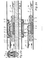
- the winch designed according to the invention has a schematic table reproduced winch frame 4, on which, according to FIG. 1, a self-tracking chassis 5 is arranged both on the front and on the rear part.
- the winch frame 4 In its central section, the winch frame 4 carries in a suitable manner the cable drums 6 for the flexible tension member, in particular a tension cable 7 for driving the rope cleaning device used in each case.
- the winch frame 4 has a base plate 8. On the underside, this base plate 8 carries a flexible, large-area clamping cushion 9, which can be inflated, expediently by compressed air.
- the winch frame 4 also carries in the middle region on its upper side two vertically acting adjusting devices 10, suitably pneumatically or hydraulically operated piston-cylinder units.
- actuators each carry at the top, e.g. B. the respective piston rod 11, a ridge shield 12 which, as shown in FIGS. 1b and 2b, is at least approximately curved in accordance with the curvature of the ridge of the plank 1.
- a ridge shield 12 On this ridge shield 12 there is an upper flexible and large-area clamping cushion 13, which is also expediently inflatable by compressed air.
- the ridge shield 12 also carries a support roller 14 on both sides and at its front and rear ends, with which it is supported on the wall of the pile, as is shown in particular in FIGS. 1b and 2b.
- a feeler roller 15 is arranged both at the front and at the rear end of the ridge shield 12, the function of which will be described below.
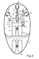
- Fig. 3 shows again schematically the basic structure of the winch described. From this it can be seen that the feeler roller 15 acts via a suitable actuator 16 on a changeover valve 17 which has three positions and three paths each. This changeover valve 17 serves to pressurize the actuating devices 10 for the ridge shield 12. The pressure medium is conveyed out of the container 19 by means of the pump 18 and returned in the manner shown.
- the feeler roller 15 and the actuator 16 are acted upon by the spring 20 in the bearing direction.
- the feeler roller 15 and the changeover valve 17 are shown in FIG. 3 in the normal operating position, in which the actuating devices have no lifting or lowering effect on the ridge shield 12.
- the impellers 5 resting on the deposit sole 2a in FIG. 3 represent the winch position according to FIG. 1 or FIG. 2, the impellers 5 resting on the sole 2b in FIG. 3 the position according to FIGS. 1a or 2a.
- the mode of operation of the winch is as follows:
- the winch may have reached the position shown in FIG. 1, wherein the feeler roller 15 with the changeover valve has assumed the position according to FIG. 3.
- the undercarriage 5 with the winch frame 4 thus rests on the deposit base 2a. 1 and 1b, the clamping cushions 9 and 13 are not yet acted upon by pressure medium.
- the tensioning cushions 9 and 13 are suitably acted upon by pressure medium, that is to say tensioned, so that they are braced on the sole 2a and the ridge of the pile 1 in the manner shown in FIGS. 2 and 2b.
- the winch can now be put into operation.
- a lower sole is reached in such a working position, e.g. B. the lowest possible position shown in Fig. 1a and 2a and in the lower part of Fig. 3 on the sole wall 2b of the board 1, the feeler roller 15 comes out of contact with the ridge wall of the board 1, so that under the action of the spring 20th the switching valve 17 is transferred to its upper switching position.
- the pressure side of the actuating devices 10 is acted upon, and the ridge shield 12 is adjusted upward via the actuating devices 10. This occurs until the feeler roller 15 comes into contact with the ridge wall of the pile 1 again and transfers the changeover valve to the middle position shown in FIG. 3, so that the further height movement of the actuating devices 10 and thus the ridge 12 is interrupted.
- All rollers 5, support rollers 14 and feeler roller 15 are suitably air-tired to ensure smooth operation.
- Fig. 1, 1a, 1b and 2, 2a and 2b also show that a build-up effect on the waste water 3 is exerted by the winch.
- the winch parts offer a certain accumulation effect, so that the right-hand normal wastewater level 3 a is lifted onto the mirror 3b.
- the winch is braced in the manner shown in Fig. 2, 2a and 2b, so in particular the tensioning pad 9 is inflated, the arrangement and shape of the tensioning pad 9 results in an increased accumulation effect on the waste water 3, so that in the direction of flow in front of the winch now the higher wastewater level 3c is reached.
- the winch therefore performs a kind of weir function.
- Fig. 4 shows purely schematically a special embodiment of the landing gear of the winch according to the invention.
- the wheel pairs are arranged in the following manner.
- Each impeller 20 and an associated idler wheel 21 of the undercarriage 4 are rigidly coupled in their assignment to one another, namely by an angled coupling linkage 22.
- This coupling linkage 22 in turn is pivotally mounted on the winch frame 4 about an axis 23 running parallel to the direction of travel. 4
- the lever arm of the coupling linkage 22 between the axis 23 and the impeller 20 is dimensioned smaller than the lever arm on the coupling linkage 22 between the axis 23 and the guide wheel 21.
Landscapes
- Health & Medical Sciences (AREA)
- Life Sciences & Earth Sciences (AREA)
- Engineering & Computer Science (AREA)
- Hydrology & Water Resources (AREA)
- Public Health (AREA)
- Water Supply & Treatment (AREA)
- Sewage (AREA)
- Cleaning In General (AREA)
Applications Claiming Priority (2)
| Application Number | Priority Date | Filing Date | Title |
|---|---|---|---|
| DE3042750 | 1980-11-13 | ||
| DE19803042750 DE3042750A1 (de) | 1980-11-13 | 1980-11-13 | Winde fuer ein sielreinigungsgeraet |
Publications (1)
| Publication Number | Publication Date |
|---|---|
| EP0052272A1 true EP0052272A1 (fr) | 1982-05-26 |
Family
ID=6116633
Family Applications (1)
| Application Number | Title | Priority Date | Filing Date |
|---|---|---|---|
| EP19810109091 Ceased EP0052272A1 (fr) | 1980-11-13 | 1981-10-28 | Treuil pour un appareil de nettoyage des égouts |
Country Status (2)
| Country | Link |
|---|---|
| EP (1) | EP0052272A1 (fr) |
| DE (1) | DE3042750A1 (fr) |
Cited By (6)
| Publication number | Priority date | Publication date | Assignee | Title |
|---|---|---|---|---|
| DE3239756A1 (de) * | 1982-10-27 | 1984-05-10 | Günter Dipl.-Ing. 2000 Hamburg Kupczik | Verfahren und vorrichtung zur reinigung von sielrohren |
| WO1988008939A1 (fr) * | 1987-05-12 | 1988-11-17 | Loefgren Ulf | Dispositif pour le travail dans des conduites |
| WO1991005116A1 (fr) * | 1989-10-04 | 1991-04-18 | Tate Pipe Lining Processes Limited | Methode et appareil pour curer les egouts |
| FR2671298A1 (fr) * | 1991-01-07 | 1992-07-10 | Lorini Jean Luc | Engin de curage destine a curer automatiquement les egouts visitables. |
| GB2253257A (en) * | 1989-10-04 | 1992-09-02 | Tate Pipe Lining Processes Lim | Apparatus and method for clearing sewers |
| AT398325B (de) * | 1992-09-11 | 1994-11-25 | Moser Martin | Fortbewegungsvorrichtung zum durchfahren von rohrförmigen kanälen od. dgl. |
Citations (5)
| Publication number | Priority date | Publication date | Assignee | Title |
|---|---|---|---|---|
| US2670178A (en) * | 1950-07-01 | 1954-02-23 | Walter C Clevenger | Jack leg pulley |
| DE1076583B (de) * | 1956-09-01 | 1960-02-25 | Julius Mueller | Kanalreinigungsgeraet |
| US3593749A (en) * | 1969-08-04 | 1971-07-20 | Edwin E Reardon | Pipeline pig stopper |
| DE2349454A1 (de) * | 1972-10-02 | 1974-04-11 | Bendix Corp | Fahrzeug zum abbau von gestein in einem grubenstollen |
| US4201597A (en) * | 1976-06-21 | 1980-05-06 | Armstrong James A | No dig seepage pit cleaner |
-
1980
- 1980-11-13 DE DE19803042750 patent/DE3042750A1/de not_active Withdrawn
-
1981
- 1981-10-28 EP EP19810109091 patent/EP0052272A1/fr not_active Ceased
Patent Citations (5)
| Publication number | Priority date | Publication date | Assignee | Title |
|---|---|---|---|---|
| US2670178A (en) * | 1950-07-01 | 1954-02-23 | Walter C Clevenger | Jack leg pulley |
| DE1076583B (de) * | 1956-09-01 | 1960-02-25 | Julius Mueller | Kanalreinigungsgeraet |
| US3593749A (en) * | 1969-08-04 | 1971-07-20 | Edwin E Reardon | Pipeline pig stopper |
| DE2349454A1 (de) * | 1972-10-02 | 1974-04-11 | Bendix Corp | Fahrzeug zum abbau von gestein in einem grubenstollen |
| US4201597A (en) * | 1976-06-21 | 1980-05-06 | Armstrong James A | No dig seepage pit cleaner |
Cited By (6)
| Publication number | Priority date | Publication date | Assignee | Title |
|---|---|---|---|---|
| DE3239756A1 (de) * | 1982-10-27 | 1984-05-10 | Günter Dipl.-Ing. 2000 Hamburg Kupczik | Verfahren und vorrichtung zur reinigung von sielrohren |
| WO1988008939A1 (fr) * | 1987-05-12 | 1988-11-17 | Loefgren Ulf | Dispositif pour le travail dans des conduites |
| WO1991005116A1 (fr) * | 1989-10-04 | 1991-04-18 | Tate Pipe Lining Processes Limited | Methode et appareil pour curer les egouts |
| GB2253257A (en) * | 1989-10-04 | 1992-09-02 | Tate Pipe Lining Processes Lim | Apparatus and method for clearing sewers |
| FR2671298A1 (fr) * | 1991-01-07 | 1992-07-10 | Lorini Jean Luc | Engin de curage destine a curer automatiquement les egouts visitables. |
| AT398325B (de) * | 1992-09-11 | 1994-11-25 | Moser Martin | Fortbewegungsvorrichtung zum durchfahren von rohrförmigen kanälen od. dgl. |
Also Published As
| Publication number | Publication date |
|---|---|
| DE3042750A1 (de) | 1982-06-16 |
Similar Documents
| Publication | Publication Date | Title |
|---|---|---|
| DE1013532B (de) | Fahrzeugaufhaengung | |
| DE2606252A1 (de) | Bohrvorrichtung | |
| EP0052272A1 (fr) | Treuil pour un appareil de nettoyage des égouts | |
| EP0142529B1 (fr) | Echafaudage a progression par moteur pour batiments | |
| DE3049611C2 (de) | Überfahrbrücke | |
| DE3447978C2 (fr) | ||
| DE2831501A1 (de) | Vorrichtung zum sammeln und abraeumen von schlamm | |
| DE19546845B4 (de) | Saugbaggerschiff mit einer an einem Kabel aufgehängten Saugvorrichtung, die mit einem Dünungskompensator versehen ist | |
| WO1994013894A1 (fr) | Camion dragueur de boue a pompe aspirante | |
| DE2904041A1 (de) | Verfahren und einrichtung zum verfestigen des kantenbereiches von platten aus einem poroesen werkstoff | |
| DE3303207C2 (de) | Überfahrbrücke für Rampen | |
| DE4032892C1 (fr) | ||
| DE2203865C3 (de) | Schlammräumer für Klärbecken mit gewichtsbelastetem Räumschild | |
| DE2904404A1 (de) | Geraet zum entladen von fahrzeugen | |
| EP0509345A2 (fr) | Procédé d'exploitation et de régénération de couche filtrante et les couches filtrantes appropriées | |
| DE3306362A1 (de) | Druck-band-filter, insbesondere zur entwaesserung von feinkohle | |
| DE3490207T1 (de) | Schabevorrichtung für Absetzbecken | |
| DE29909623U1 (de) | Fahrzeug zum Lösen und Absaugen von Verunreinigungen aus Straßenabläufen | |
| DE9204714U1 (de) | Hydraulische Absetzeinrichtung für Wechselaufbauten | |
| DE2945735C2 (de) | Holztränkvorrichtung | |
| DE2710663C3 (de) | Schwimmende automatische Vakuum- Trommel-Bandfilter-Vorrichtung | |
| AT19452B (de) | Hydraulische Abstützung der Schiffe in Docks und Wagen der Schiffs-Hebewerke. | |
| DE3104555A1 (de) | Ueberfahrbruecke fuer rampen | |
| DE68906268T2 (de) | Rampe fuer ferryboote oder aehnliche. | |
| DE2300579C3 (de) | Kran mit zusammenklappbarem Mast und Ausleger |
Legal Events
| Date | Code | Title | Description |
|---|---|---|---|
| PUAI | Public reference made under article 153(3) epc to a published international application that has entered the european phase |
Free format text: ORIGINAL CODE: 0009012 |
|
| AK | Designated contracting states |
Designated state(s): DE FR GB IT NL |
|
| 17P | Request for examination filed |
Effective date: 19820508 |
|
| STAA | Information on the status of an ep patent application or granted ep patent |
Free format text: STATUS: THE APPLICATION HAS BEEN REFUSED |
|
| 18R | Application refused |
Effective date: 19840420 |
|
| RIN1 | Information on inventor provided before grant (corrected) |
Inventor name: MAGER, WERNER |