EP0052362A1 - Système d'initialisation rapide d'égaliseurs transversaux - Google Patents
Système d'initialisation rapide d'égaliseurs transversaux Download PDFInfo
- Publication number
- EP0052362A1 EP0052362A1 EP81109695A EP81109695A EP0052362A1 EP 0052362 A1 EP0052362 A1 EP 0052362A1 EP 81109695 A EP81109695 A EP 81109695A EP 81109695 A EP81109695 A EP 81109695A EP 0052362 A1 EP0052362 A1 EP 0052362A1
- Authority
- EP
- European Patent Office
- Prior art keywords
- sequence
- values
- symbol
- phase
- fourier transform
- Prior art date
- Legal status (The legal status is an assumption and is not a legal conclusion. Google has not performed a legal analysis and makes no representation as to the accuracy of the status listed.)
- Granted
Links
- 238000012360 testing method Methods 0.000 claims abstract description 20
- 230000000737 periodic effect Effects 0.000 claims abstract description 14
- 238000005070 sampling Methods 0.000 claims abstract description 10
- 230000003134 recirculating effect Effects 0.000 claims abstract description 6
- 238000005311 autocorrelation function Methods 0.000 claims abstract description 3
- 238000004364 calculation method Methods 0.000 claims description 2
- 230000004044 response Effects 0.000 description 23
- 230000005540 biological transmission Effects 0.000 description 16
- 238000010586 diagram Methods 0.000 description 4
- 238000009825 accumulation Methods 0.000 description 3
- 238000000034 method Methods 0.000 description 3
- 238000013459 approach Methods 0.000 description 2
- 239000011159 matrix material Substances 0.000 description 2
- 238000012545 processing Methods 0.000 description 2
- 230000001360 synchronised effect Effects 0.000 description 2
- 238000010276 construction Methods 0.000 description 1
- 230000009849 deactivation Effects 0.000 description 1
- 230000006735 deficit Effects 0.000 description 1
- 230000001934 delay Effects 0.000 description 1
- 238000001514 detection method Methods 0.000 description 1
- 238000005259 measurement Methods 0.000 description 1
- 238000005457 optimization Methods 0.000 description 1
- 239000002243 precursor Substances 0.000 description 1
- 238000012549 training Methods 0.000 description 1
- 238000012546 transfer Methods 0.000 description 1
Images





Classifications
-
- H—ELECTRICITY
- H04—ELECTRIC COMMUNICATION TECHNIQUE
- H04L—TRANSMISSION OF DIGITAL INFORMATION, e.g. TELEGRAPHIC COMMUNICATION
- H04L25/00—Baseband systems
- H04L25/02—Details ; arrangements for supplying electrical power along data transmission lines
- H04L25/03—Shaping networks in transmitter or receiver, e.g. adaptive shaping networks
- H04L25/03006—Arrangements for removing intersymbol interference
- H04L25/03012—Arrangements for removing intersymbol interference operating in the time domain
- H04L25/03114—Arrangements for removing intersymbol interference operating in the time domain non-adaptive, i.e. not adjustable, manually adjustable, or adjustable only during the reception of special signals
- H04L25/03133—Arrangements for removing intersymbol interference operating in the time domain non-adaptive, i.e. not adjustable, manually adjustable, or adjustable only during the reception of special signals with a non-recursive structure
Definitions
- This invention relates to automatic equalizers for compensating distorting data transmission channels and more particularly to rapid initial adjustment of such equalizers with respect to channel characteristics.
- the equalizer generally consists of a transversal filter with adjustable tap coefficients.
- the optimum tap gains can theoretically be calculated from a system of simultaneous equations. Automatic equalizers solve these equations by iterative algorithms, which lead to results of sufficient precision for practical use after a finite number of iterations. After initial adjustment, the receiver associated with the equalizer is ready for data reception.
- T m and T S are respectively message time and start-up time.
- T M 12 miliseconds at a 9,600-bit-per- second rate.
- T S 250 miliseconds to start up.
- High-speed data sets themselves often require longer absolute start-up times because more sophisticated carrier and timing control as well as equalizer control are required. In this example 95 percents of the connection time for the message is needed for start up, while only 5 percents is used for actual information transfer.
- An object of the invention is to provide a fast start-up system for transversal equalizers which can overcome the above drawbacks and shorten the start-up time.
- a fast start-up system for a transversal equalizer comprising means provided in a transmitter for generating a periodic symbol sequence with a period L, the auto correlation function of said sequence being completely 0 except for its center; means for generating and transmitting a test signal based upon said generated symbol sequence; means provided in a receiver for generating the same symbol sequence as that generated in the transmitter in a proper phase relation thereto according to a received signal; means for calculating the correlation between L sampled values obtained by sampling the received test signal at the symbol interval and a sequence obtained by recirculating said periodic symbol sequence for each of consecutive M shifted phases; means for calculating the correlation between L sampled values obtained by sampling the received test signal at the symbol interval with a phase differring from the phase of said first-mentioned sampled values by an amount corresponding to one half of the symbol interval and a sequence obtained by recirculating said periodic symbol sequence for each of M' consecutive shifted phases; means for multiplying said calculated M + M' correlation values by
- thin lines represent time-serial binary or analog signal lines and thick lines represent parallel binary signal lines.
- the construction according to the invention comprises a first section for removing phase disturbances caused by the transmission channel, such as frequency offsets and carrier phase jitters, from the input signal, a second section for estimating the impulse response of the transmission channel from the input signal removed of the transmission channel phase disturbances, and a third section for controlling the tap coefficients of a transversal filter constituting an equalizer according to the estimated impulse response.
- phase disturbances caused by the transmission channel such as frequency offsets and carrier phase jitters
- a periodic symbol sequence a 0 , a 1 , ... , a L-1 , a 0 , a 1 , ... with a period L equal to or longer than the ratio between the significant duration of impulse response and the symbol interval is transmitted.
- phase variation term in equation (2) can be removed under the following conditions as will be described below:
- Equation (3) signifies where ⁇ m0 is 1 only when m is 0 and is 0 when m is other than 0.
- equation (4) can be rewritten as, indicating that the phase variation term can be extracted.
- phase rotation is effected in the reverse direction by an amount corresponding to the extracted phase variation term.
- the approximation ⁇ i contains the phase term h p as well.
- the phase term h is constant and does not constitute any obstruction to the adjustment of an automatic equalizer.
- condition (3) can be met by assigning the afore-mentioned values of a and a to all the other M sequences and quadratic residue sequences.
- the second section according to the invention i.e., means for estimating the impulse response from sampled values free from phase variation
- the vector R represents L measured values containing information about the impulse response sampled values.
- M ( ⁇ L) impulse response sampled values from the measured values a least square method is well known. According to this method, since R can be expressed, from equation (1), as where
- [A*A] is L times the unit matrix.
- the estimation of the impulse response on the basis of equation (10) can thus be done very simply by generating a periodic symbol sequence on the receiving side and taking the inner product of its recirculated sequence and L received sampled values. If the phase of the symbol sequence generated on the receiving side is deviated, however, it is necessary to generate a symbol sequence at a proper phase or return the estimated response to the proper position through the detection of the amount of the recirculated shift, because the estimated impulse response is obtained through the recirculation.
- the number of measurement values is L, i.e., the value of one period of the symbol sequence
- estimation under a similar principle may be obtained by setting the number to an integral multiple of L. In this case, the precision of estimation can be improved by extending the training period.
- the principle of the third section according to the invention i.e., means for setting the optimum value of the tap gain of the transversal automatic equalizer without being affected by the sampling phase.
- H (h L , h L-1 , ..., h L-(m-1) )
- H (h L , h L-1 , ..., h L-(m-1) )
- the frequency characteristic which is reflexed Nyquist band is obtained as where - ⁇ ⁇ ⁇
- ⁇ is a sampling phase or and H( ⁇ ) is the frequency characteristic of the transmission channel.
- the purpose of the equalizer is to provide, where - ⁇ ⁇ ⁇ and E( ⁇ ) is the characteristic of the equalizer.
- T stands. From equations (12). and (13), is obtained.
- the invention aims to provide means for setting the initial value of the transversal automatic equalizer tap gain by avoiding such a situation.
- the estimation of equation (11) is done for H and H' which is out of phase relative to H by T/ 2, and a vector H T/2 is obtained by interleaving the individual elements.
- the vector R' used instead of R in equation (11) includes as a component the element given as according to equation (6). In other words, the estimation of the phase variation is made for every T seconds, and the estimated value is used even after the lapse of T/2.
- the optimization of the tap gain can be obtained through the inverse Fourier transform of N values resulting from dividing Nq( ⁇ i ) by the i-th value of the estimated transmission channel characteristic.
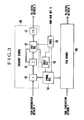
- a real and an imaginary part of a demodulated signal obtained as a result of product demodulation of a quadrature amplitude modulated signal in a demodulator circuit, not shown, are applied to terminals 1 and 2, respectively.
- the real and imaginary parts of the signal are sampled by sample/hold circuits 3 and 4, respectively.
- the sampled signals are converted through respective analog-to- digital (A/D) converters 5 and 6 into corresponding digital signals.
- A/D analog-to- digital
- the fast start-up system comprises a phase compensation network 7 for removing from the digital signals the phase disturbance such as frequency offsets and carrier phase jitters introduced into the digital signals in the transmission line, a fast learn network 8 for estimating the impulse response of the transmission line from the digital signals removed of the phase disturbances, and an equalization control network 9 for controlling the tap coefficient of a transversal filter constituting an equalizer 10 according to the estimated impulse response.
- a phase compensation network 7 for removing from the digital signals the phase disturbance such as frequency offsets and carrier phase jitters introduced into the digital signals in the transmission line
- a fast learn network 8 for estimating the impulse response of the transmission line from the digital signals removed of the phase disturbances
- an equalization control network 9 for controlling the tap coefficient of a transversal filter constituting an equalizer 10 according to the estimated impulse response.
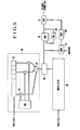
- the phase compensation network 7 materializing the first section in the principle underlying the invention will be described with reference to Figs. 2 and 7A to 7H. In the description below, processing of the real part of signal is discussed, and it is to be understood that a similar processing is made for the imaginary part of signal.
- the outputs of the A/D converters 5 and 6 shown in Fig. 1 are fed to a peak detector 13 which will be described later in detail. When the peak detector 13 detects the peak with +T/2 accuracy in the impulse response carrying the first symbol a 0 appearing at the outputs of the A/D converters 5 and 6, it generates a trigger pulse.
- the contents of the shift register 11 are shifted out and also recirculated under the control of L in-frame pulses generated from the pulse generator 16.
- the pulse output of the pulse generator 16 is also directed to a symbol generator 14 (to be described later in detail), and symbols (Fig. 7F) for one period are sequentially generated according to L in-frame pulses.
- Each shift-out output (Fig. 7E) of the shift register 11 and each generated symbol are multiplied by a multiplier 12, and the results are accumulated (Fig. 7G) in an accumulator 15 which is cleared by the frame pulse at the symbol rate.
- the symbol generator 14 is initialized such that it generates the sequence a 0 , a l , ...
- the result of accumulation is i in the equation (4).
- the result of accumulation is coupled at the symbol rate to a phase detector 17 in a phase detector section 170.
- the phase angle of i is calculated in the circuit 17 from the real and imaginary parts of the accumulation result, and the result of calculation is fed to a ROM 18 to generate complex numbers each consisting of a cosine real part and a minus sine imaginary part, i.e., exp (-j arg i ) at the symbol rate.
- exp (-j arg i ) is held.
- the output of the phase detector 170 is multiplied in multipliers 19 and 20 by the outputs of the A/D converters 5 and 6 for every period T/2.
- the outputs of the multipliers 19 and 20 are added together in an adder 21.
- the output of the adder is held for the period T/2.
- the network 8 for estimating the impulse-response which corresponds to the second section in the principle underlying the invention, will now be described with reference to Figs. 3 and 7I to 7M.
- the output of the adder 21 (Fig. 2) is multiplied in a multiplier 40 by a symbol generated from a symbol generator 44.
- the symbol generator 44 is driven by a frame pulse synchronized to the frame pulse from the pulse generator 16 (Fig. 2) and 2L in-frame pulses (Fig. 7J) generated from a pulse generator 45 and multiplies one output (in the period T/2) of the adder 21 by L symbols (Fig. 7K).
- the output of the multiplier 40 is added in an adder 41 to the output of an 2L-stage shift register 42, which shifts out under the control of L pulses (Fig. 7I) generated from the pulse generator 45 during the period T/2.
- the output of the adder 41 is shifted into a shift register 42.
- C l C 1 + ⁇ i a i
- ..., C L-1 C L-1 + ⁇ i a L-1 (Fi g . 7L).
- the contents of the shift register 42 are held cleared while a timer 46 is providing a reset pulse output.
- the timer 46 continues to provide the reset pulse until a predetermined period of time has elapsed from the appearance of the trigger signal from the aforementioned peak detector 13 (Fig. 2), and after the lapse of a period LT from the deactivation of delivery of the reset pulse, it transmits a signal to the pulse generator 45 to stop the generation of pulses.
- the timer 46 discontinues the provision of the reset pulse, the initial state of the symbol generator 44 is set to a predetermined value.
- 2L accumulators each constituted by the adder 41 and shift register 42 calculate H in the equation (11) and ⁇ ' which is out of phase relative to H by T/ 2.
- the contents of the shift register 42 are L times h L , h L-1 , ..., h L-(M-1) , h L-1/2 , h L-3/2 , ..., hL-(M-1)-1/2 ( F ig. 7 M ).
- An attenuator 43 multiplies the contents of the shift register 42 by a value corresponding to 1/L.
- the equalization control or tap coefficient control network 9 realizing the third portion of the principle underlying the invention will be described with reference to F ig. 4.
- the output of the attenuator (Fig. 3) is fed in the form expressed by the equation (16) to a memory section of a high rate Fourier transform processor 47.
- the processor 47 provides Fourier transform for N points, N being a power of 2 greater than 2L, and inserts 0 for N - 2L points.
- a divider 48 divides N Nyquist characteristic values stored in memory by the corresponding processor outputs. The result of division corresponds to the frequency characteristic that is to be realized by the equalizer.
- the result of division is returned by a high speed inverse Fourier converter 49 to a time region.
- the numerical value returned to the time region is directly supplied as the optimum complex values W 1 , ..., W k , where k is the number of taps, of tap gain of the transversal automatic equalizer 10 which is constituted by a delay line tapped at an interval of T/2.
- the impulse response of the transmission channel is estimated in the network 8 from the test signal free from phase variations that is provided from the phase compensation network 7, and the equalization control network 9 determines the optimum value of the filter coefficient of the equalization network 10 according to the estimated impulse response.
- F ig. 5 shows a block diagram showing an example of the peak detector 13 shown in Fig. 2.
- the outputs of the A/ D converters 5 and 6 (Fig. 2) are fed to a transversal filter 90, which includes a (2L-l)-stage shift register 22 for shifting in for every period T/2 and means for weighting the odd number order outputs of the shift register by a symbol sequence a 0 to a L-1 .
- the output of the transversal filter 90 is noise before the arrival of the first test signal energy at the receiving terminal and, after the arrival of the test signal, assumes sequential impulse response precursors h 0 , h l/2 , h 1 , ..., h p inclusive of phase rotation.
- the output of the transversal filter 90 is fed to an absolute value calculator 25, which calculates the sum of the squares of the real and imaginary parts and provides the square of the absolute value thereof.
- This value is compared-in a comparator 28 with a value stored in a register 29. If the compared output of the absolute value calculator 29 is greater, the contents of the register 28 are renewed with that value. If the output of the absolute value calculator 25 is less, a trigger pulse is gated through a gate 31 to the outside. The gate 31 is driven by the output of a comparator 27, which generates a trigger signal when the output of the absolute value calculator 25 exceeds a threshold higher than the noise level, and is held open for a definite period (for instance LT).
- Fig. 6 shows an example of the symbol sequence generator 14 in case when the period is 15.
- Flip-flops 32, 33, 34 and 35 are set to an initial state of 1 and are driven by the clock generated from the clock generator 16 (Fig. 2) mentioned before.
- the outputs of the flip-flops 34 and 35 are coupled to an exclusive OR gate 36, and the exclusive OR output thereform is fed back to the flip-flop 32 while it is also fed to an adder 37, to which a reference voltage generated from a reference voltage generator 38 is also supplied.
- the output of the adder is multiplied by a constant in an amplifier 39.
- the output of the amplifier 39 corresponds to a and S in the equation (7).
- test signal suited to the transmission line is generated according to the output signal of an amplifier 39 provided on the transmitting side.
Landscapes
- Engineering & Computer Science (AREA)
- Power Engineering (AREA)
- Computer Networks & Wireless Communication (AREA)
- Signal Processing (AREA)
- Cable Transmission Systems, Equalization Of Radio And Reduction Of Echo (AREA)
- Filters That Use Time-Delay Elements (AREA)
Applications Claiming Priority (4)
| Application Number | Priority Date | Filing Date | Title |
|---|---|---|---|
| JP161534/80 | 1980-11-17 | ||
| JP16153480A JPS5784632A (en) | 1980-11-17 | 1980-11-17 | Data transmission device |
| JP174198/80 | 1980-12-10 | ||
| JP55174198A JPS5797736A (en) | 1980-12-10 | 1980-12-10 | Phase compensator |
Publications (2)
| Publication Number | Publication Date |
|---|---|
| EP0052362A1 true EP0052362A1 (fr) | 1982-05-26 |
| EP0052362B1 EP0052362B1 (fr) | 1985-01-30 |
Family
ID=26487631
Family Applications (1)
| Application Number | Title | Priority Date | Filing Date |
|---|---|---|---|
| EP81109695A Expired EP0052362B1 (fr) | 1980-11-17 | 1981-11-14 | Système d'initialisation rapide d'égaliseurs transversaux |
Country Status (5)
| Country | Link |
|---|---|
| US (1) | US4430743A (fr) |
| EP (1) | EP0052362B1 (fr) |
| BR (1) | BR8107464A (fr) |
| CA (1) | CA1171470A (fr) |
| DE (1) | DE3168697D1 (fr) |
Cited By (10)
| Publication number | Priority date | Publication date | Assignee | Title |
|---|---|---|---|---|
| FR2528643A1 (fr) * | 1982-06-14 | 1983-12-16 | Trt Telecom Radio Electr | Procede destine a reduire le temps de convergence d'un annuleur d'echo et dispositif utilise pour mettre en oeuvre ce procede |
| GB2128456A (en) * | 1982-10-01 | 1984-04-26 | Standard Telephones Cables Ltd | Improvements in or relating to data transmission and receiving systems |
| FR2541837A1 (fr) * | 1983-02-25 | 1984-08-31 | Trt Telecom Radio Electr | Procede de reduction du temps de convergence d'un annuleur d'echo et dispositif pour mettre en oeuvre ce procede |
| EP0140809A1 (fr) * | 1983-10-28 | 1985-05-08 | Etablissement Public de Diffusion dit "Télédiffusion de France" | Dispositif de correction d'échos, notamment pour système de télédiffusion de données |
| EP0270706A1 (fr) * | 1982-06-14 | 1988-06-15 | Telecommunications Radioelectriques Et Telephoniques T.R.T. | Procédé destiné à réduire le temps de convergence d'un annuleur d'écho |
| EP0496677A3 (en) * | 1991-01-23 | 1992-09-23 | Fujitsu Limited | Adaptive equalizers |
| EP0454445A3 (en) * | 1990-04-26 | 1992-09-30 | Fujitsu Limited | Waveform equalizer using a neural network |
| EP0423775A3 (en) * | 1989-10-18 | 1993-02-24 | Nec Corporation | Receiver capable of removing both intersymbol interference and frequency offset |
| EP0604208A3 (fr) * | 1992-12-25 | 1995-01-18 | Nippon Electric Co | Equilibreur adaptatif. |
| WO1999050969A3 (fr) * | 1998-03-27 | 2000-01-13 | Ericsson Telefon Ab L M | Egaliseur utile dans des systemes de modulation a porteuses multiples |
Families Citing this family (19)
| Publication number | Priority date | Publication date | Assignee | Title |
|---|---|---|---|---|
| US4561100A (en) * | 1981-01-20 | 1985-12-24 | Sanyo Electric Co., Ltd. | Digital signal receiver |
| JPS58121838A (ja) * | 1981-12-28 | 1983-07-20 | Fujitsu Ltd | 自動等化器 |
| IT1158646B (it) * | 1982-06-11 | 1987-02-18 | Consiglio Nazionale Ricerche | Sistema di equalizzazione adattiva auto-ortogonalizzante nel dominio delle frequenze discrete ed equalizzatore che attua il sistema |
| DE3376943D1 (en) * | 1983-06-30 | 1988-07-07 | Ibm | Starting-up method for an echo canceller filter, and communication system using this method |
| US4675863A (en) | 1985-03-20 | 1987-06-23 | International Mobile Machines Corp. | Subscriber RF telephone system for providing multiple speech and/or data signals simultaneously over either a single or a plurality of RF channels |
| US4825448A (en) * | 1986-08-07 | 1989-04-25 | International Mobile Machines Corporation | Subscriber unit for wireless digital telephone system |
| US5168507A (en) * | 1986-08-07 | 1992-12-01 | International Mobile Machines Corporation | Automatic adaptive equalizer |
| US4811097A (en) * | 1987-10-29 | 1989-03-07 | Videotek, Inc. | Video signal processor |
| DK168750B1 (da) * | 1990-05-01 | 1994-05-30 | Dancall Telecom As | Fremgangsmåde til modforvrængning i en modtager af signaler, der har passeret en transmissionskanal |
| JPH06309794A (ja) * | 1993-04-26 | 1994-11-04 | Toshiba Corp | 再生信号等化装置 |
| US5778029A (en) * | 1993-05-13 | 1998-07-07 | Lockheed Martin Aerospace Corporation | Signal conditioner with symbol addressed lookup table producing values which compensate linear and non-linear distortion using transversal filter |
| US5546383A (en) * | 1993-09-30 | 1996-08-13 | Cooley; David M. | Modularly clustered radiotelephone system |
| US6018317A (en) * | 1995-06-02 | 2000-01-25 | Trw Inc. | Cochannel signal processing system |
| US6088389A (en) * | 1997-05-13 | 2000-07-11 | Lucent Technologies, Inc. | System and method for training a plurality of equalizers and a modem employing the system or method |
| US6891887B1 (en) | 1998-05-27 | 2005-05-10 | 3Com Corporation | Multi-carrier LAN adapter device using interpolative equalizer |
| US6704317B1 (en) | 1998-05-27 | 2004-03-09 | 3Com Corporation | Multi-carrier LAN modem server |
| US6507585B1 (en) | 1998-05-27 | 2003-01-14 | 3Com Corporation | Multi-carrier LAN adapter device using frequency domain equalizer |
| US6603811B1 (en) | 1998-05-29 | 2003-08-05 | 3Com Corporation | Low complexity frequency domain equalizer having fast re-lock |
| US6377683B1 (en) | 1998-05-29 | 2002-04-23 | 3Com Corporation | Low complexity frequency domain echo canceller for DMT transceivers |
Citations (5)
| Publication number | Priority date | Publication date | Assignee | Title |
|---|---|---|---|---|
| US3935535A (en) * | 1974-09-09 | 1976-01-27 | Hycom Incorporated | Fast equalization acquisition for automatic adaptive digital modem |
| US4027258A (en) * | 1976-06-01 | 1977-05-31 | Xerox Corporation | Time domain automatic equalizer with frequency domain control |
| US4047013A (en) * | 1975-07-09 | 1977-09-06 | International Business Machines Corporation | Method and apparatus for fast determination of initial transversal equalizer coefficient values |
| US4089061A (en) * | 1975-12-30 | 1978-05-09 | International Business Machines Corporation | Method and apparatus for determining the initial values of the coefficients of a complex transversal equalizer |
| US4152649A (en) * | 1976-07-08 | 1979-05-01 | International Business Machines Corporation | Channel equalization apparatus and method using the Fourier transform technique |
Family Cites Families (2)
| Publication number | Priority date | Publication date | Assignee | Title |
|---|---|---|---|---|
| US3715666A (en) | 1971-03-30 | 1973-02-06 | Bell Telephone Labor Inc | Fast start-up system for transversal equalizers |
| US4370726A (en) | 1980-07-25 | 1983-01-25 | Rca Corporation | Signal correlation means employing charged-coupled device type shift registers |
-
1981
- 1981-11-13 US US06/321,101 patent/US4430743A/en not_active Expired - Lifetime
- 1981-11-14 EP EP81109695A patent/EP0052362B1/fr not_active Expired
- 1981-11-14 DE DE8181109695T patent/DE3168697D1/de not_active Expired
- 1981-11-17 BR BR8107464A patent/BR8107464A/pt not_active IP Right Cessation
- 1981-11-17 CA CA000390250A patent/CA1171470A/fr not_active Expired
Patent Citations (5)
| Publication number | Priority date | Publication date | Assignee | Title |
|---|---|---|---|---|
| US3935535A (en) * | 1974-09-09 | 1976-01-27 | Hycom Incorporated | Fast equalization acquisition for automatic adaptive digital modem |
| US4047013A (en) * | 1975-07-09 | 1977-09-06 | International Business Machines Corporation | Method and apparatus for fast determination of initial transversal equalizer coefficient values |
| US4089061A (en) * | 1975-12-30 | 1978-05-09 | International Business Machines Corporation | Method and apparatus for determining the initial values of the coefficients of a complex transversal equalizer |
| US4027258A (en) * | 1976-06-01 | 1977-05-31 | Xerox Corporation | Time domain automatic equalizer with frequency domain control |
| US4152649A (en) * | 1976-07-08 | 1979-05-01 | International Business Machines Corporation | Channel equalization apparatus and method using the Fourier transform technique |
Non-Patent Citations (1)
| Title |
|---|
| IEEE 1974 International Conference on Communications, June 17-19, 1974, Minneapolis-New York (US) K.H. MUELLER: "Cyclic Equalization - A New Rapidly-Converging Adaptive Aqualization Technique for Synchronous Data Communication", page 9B-1 to 9B-5 * page 9B-1 to 9B-5 * * |
Cited By (17)
| Publication number | Priority date | Publication date | Assignee | Title |
|---|---|---|---|---|
| EP0096936A1 (fr) * | 1982-06-14 | 1983-12-28 | Telecommunications Radioelectriques Et Telephoniques T.R.T. | Procédé destiné à réduire le temps de convergence d'un annuleur d'écho et dispositif utilisé pour mettre en oeuvre ce procédé |
| EP0270706A1 (fr) * | 1982-06-14 | 1988-06-15 | Telecommunications Radioelectriques Et Telephoniques T.R.T. | Procédé destiné à réduire le temps de convergence d'un annuleur d'écho |
| FR2528643A1 (fr) * | 1982-06-14 | 1983-12-16 | Trt Telecom Radio Electr | Procede destine a reduire le temps de convergence d'un annuleur d'echo et dispositif utilise pour mettre en oeuvre ce procede |
| GB2128456A (en) * | 1982-10-01 | 1984-04-26 | Standard Telephones Cables Ltd | Improvements in or relating to data transmission and receiving systems |
| FR2541837A1 (fr) * | 1983-02-25 | 1984-08-31 | Trt Telecom Radio Electr | Procede de reduction du temps de convergence d'un annuleur d'echo et dispositif pour mettre en oeuvre ce procede |
| EP0117596A1 (fr) * | 1983-02-25 | 1984-09-05 | Telecommunications Radioelectriques Et Telephoniques T.R.T. | Procédé de réduction du temps de convergence d'un annuleur d'écho et dispositif pour mettre en oeuvre ce procédé |
| EP0140809A1 (fr) * | 1983-10-28 | 1985-05-08 | Etablissement Public de Diffusion dit "Télédiffusion de France" | Dispositif de correction d'échos, notamment pour système de télédiffusion de données |
| FR2556530A1 (fr) * | 1983-10-28 | 1985-06-14 | Telediffusion Fse | Dispositif de correction d'echos, notamment pour systeme de diffusion de donnees |
| EP0423775A3 (en) * | 1989-10-18 | 1993-02-24 | Nec Corporation | Receiver capable of removing both intersymbol interference and frequency offset |
| US5272723A (en) * | 1990-04-26 | 1993-12-21 | Fujitsu Limited | Waveform equalizer using a neural network |
| EP0454445A3 (en) * | 1990-04-26 | 1992-09-30 | Fujitsu Limited | Waveform equalizer using a neural network |
| EP0496677A3 (en) * | 1991-01-23 | 1992-09-23 | Fujitsu Limited | Adaptive equalizers |
| US5434883A (en) * | 1991-01-23 | 1995-07-18 | Fujitsu Limited | Adaptive equalizers |
| EP0604208A3 (fr) * | 1992-12-25 | 1995-01-18 | Nippon Electric Co | Equilibreur adaptatif. |
| WO1999050969A3 (fr) * | 1998-03-27 | 2000-01-13 | Ericsson Telefon Ab L M | Egaliseur utile dans des systemes de modulation a porteuses multiples |
| US6185251B1 (en) | 1998-03-27 | 2001-02-06 | Telefonaktiebolaget Lm Ericsson | Equalizer for use in multi-carrier modulation systems |
| US6408022B1 (en) | 1998-03-27 | 2002-06-18 | Telefonaktiebolaget L M Ericsson | Equalizer for use in multi-carrier modulation systems |
Also Published As
| Publication number | Publication date |
|---|---|
| CA1171470A (fr) | 1984-07-24 |
| DE3168697D1 (en) | 1985-03-14 |
| BR8107464A (pt) | 1982-08-10 |
| EP0052362B1 (fr) | 1985-01-30 |
| US4430743A (en) | 1984-02-07 |
Similar Documents
| Publication | Publication Date | Title |
|---|---|---|
| EP0052362B1 (fr) | Système d'initialisation rapide d'égaliseurs transversaux | |
| US4789994A (en) | Adaptive equalizer using precursor error signal for convergence control | |
| EP0316876B1 (fr) | Circuit de réception de signaux numériques avec des moyens pour commander la phase d'échantillonnage baud par une puissance des signaux échantillonnés | |
| US4539675A (en) | Echo canceller | |
| US3524169A (en) | Impulse response correction system | |
| EP0998785B1 (fr) | Recepteur en mode rafale a egalisation adaptative et procede applicable a la remontee des donnees large bande | |
| US4872184A (en) | Digital automatic line equalizer with means for controlling tap gains of transversal filter based on mean power of output from the filter | |
| US4285061A (en) | Equalizer sample loading in voiceband data sets | |
| EP0534489B1 (fr) | Filtre apparié pour utilisation avec un égalisateur à décision récursive | |
| GB1505139A (en) | Ultrafast adaptive digital modem | |
| EP0105513B1 (fr) | Procédé de mesure de qualité d'un signal reçu par un récepteur d'un système de communication de données bidirectionnel à modulation linéaire | |
| US4262360A (en) | Method and device for detecting a pseudo-random sequence of carrier phase changes of 0° and 180° in a data receiver | |
| US3368168A (en) | Adaptive equalizer for digital transmission systems having means to correlate present error component with past, present and future received data bits | |
| EP0529585A2 (fr) | Estimateur de la réponse impulsionelle d'un canal, pour récepteur à estimation de séquence à maximum de vraisemblance, pour canaux variants rapidement | |
| US4539689A (en) | Fast learn digital adaptive equalizer | |
| US3573624A (en) | Impulse response correction system | |
| US4745625A (en) | Transition detector | |
| US5995572A (en) | Method for measuring frequency shift in digital communications using synchronization sequence and channel step response | |
| EP0027314B1 (fr) | Récepteur de données comprenant des moyens pour former des échantillons de lignes et procédé pour l'opération d'un tel récepteur de données | |
| US4969163A (en) | Timing control for Modem receivers | |
| JP6975760B2 (ja) | 自己相関器および受信機 | |
| WO2007053842A2 (fr) | Procedes et appareil pour determiner la temporisation dans un systeme de communication sans fil | |
| US5278867A (en) | Receiver system for processing signals received on diversity channels | |
| US5790600A (en) | Method of compensating differences in group propagation times between the analog filters of a transmitter and between those of a receiver for signals in phase quadrature corresponding compensation apparatus and a corresponding transmission system | |
| JP3444549B2 (ja) | サンプリング位相同期装置 |
Legal Events
| Date | Code | Title | Description |
|---|---|---|---|
| PUAI | Public reference made under article 153(3) epc to a published international application that has entered the european phase |
Free format text: ORIGINAL CODE: 0009012 |
|
| AK | Designated contracting states |
Designated state(s): DE FR GB SE |
|
| 17P | Request for examination filed |
Effective date: 19821116 |
|
| RAP1 | Party data changed (applicant data changed or rights of an application transferred) |
Owner name: NEC CORPORATION |
|
| GRAA | (expected) grant |
Free format text: ORIGINAL CODE: 0009210 |
|
| AK | Designated contracting states |
Designated state(s): DE FR GB SE |
|
| REF | Corresponds to: |
Ref document number: 3168697 Country of ref document: DE Date of ref document: 19850314 |
|
| ET | Fr: translation filed | ||
| PLBE | No opposition filed within time limit |
Free format text: ORIGINAL CODE: 0009261 |
|
| STAA | Information on the status of an ep patent application or granted ep patent |
Free format text: STATUS: NO OPPOSITION FILED WITHIN TIME LIMIT |
|
| 26N | No opposition filed | ||
| EAL | Se: european patent in force in sweden |
Ref document number: 81109695.7 |
|
| PGFP | Annual fee paid to national office [announced via postgrant information from national office to epo] |
Ref country code: SE Payment date: 19981109 Year of fee payment: 18 |
|
| PGFP | Annual fee paid to national office [announced via postgrant information from national office to epo] |
Ref country code: GB Payment date: 19981120 Year of fee payment: 18 |
|
| PGFP | Annual fee paid to national office [announced via postgrant information from national office to epo] |
Ref country code: FR Payment date: 19981125 Year of fee payment: 18 |
|
| PGFP | Annual fee paid to national office [announced via postgrant information from national office to epo] |
Ref country code: DE Payment date: 19981203 Year of fee payment: 18 |
|
| PG25 | Lapsed in a contracting state [announced via postgrant information from national office to epo] |
Ref country code: GB Free format text: LAPSE BECAUSE OF NON-PAYMENT OF DUE FEES Effective date: 19991114 |
|
| PG25 | Lapsed in a contracting state [announced via postgrant information from national office to epo] |
Ref country code: SE Free format text: LAPSE BECAUSE OF NON-PAYMENT OF DUE FEES Effective date: 19991115 |
|
| GBPC | Gb: european patent ceased through non-payment of renewal fee |
Effective date: 19991114 |
|
| EUG | Se: european patent has lapsed |
Ref document number: 81109695.7 |
|
| PG25 | Lapsed in a contracting state [announced via postgrant information from national office to epo] |
Ref country code: FR Free format text: LAPSE BECAUSE OF NON-PAYMENT OF DUE FEES Effective date: 20000731 |
|
| PG25 | Lapsed in a contracting state [announced via postgrant information from national office to epo] |
Ref country code: DE Free format text: LAPSE BECAUSE OF NON-PAYMENT OF DUE FEES Effective date: 20000901 |
|
| REG | Reference to a national code |
Ref country code: FR Ref legal event code: ST |