EP0052383A1 - Kühlmediumsverteilkörper - Google Patents
Kühlmediumsverteilkörper Download PDFInfo
- Publication number
- EP0052383A1 EP0052383A1 EP81201009A EP81201009A EP0052383A1 EP 0052383 A1 EP0052383 A1 EP 0052383A1 EP 81201009 A EP81201009 A EP 81201009A EP 81201009 A EP81201009 A EP 81201009A EP 0052383 A1 EP0052383 A1 EP 0052383A1
- Authority
- EP
- European Patent Office
- Prior art keywords
- cooling medium
- pole
- rotor
- coolant
- distribution body
- Prior art date
- Legal status (The legal status is an assumption and is not a legal conclusion. Google has not performed a legal analysis and makes no representation as to the accuracy of the status listed.)
- Granted
Links
- 239000002826 coolant Substances 0.000 title claims abstract description 88
- 238000001816 cooling Methods 0.000 claims description 9
- 230000000694 effects Effects 0.000 claims description 3
- 238000005192 partition Methods 0.000 claims description 3
- 238000009423 ventilation Methods 0.000 claims 3
- 230000015572 biosynthetic process Effects 0.000 claims 1
- 230000003716 rejuvenation Effects 0.000 claims 1
- 125000006850 spacer group Chemical group 0.000 description 5
- 238000004804 winding Methods 0.000 description 4
- 229910000831 Steel Inorganic materials 0.000 description 2
- 230000003068 static effect Effects 0.000 description 2
- 239000010959 steel Substances 0.000 description 2
- 229910000838 Al alloy Inorganic materials 0.000 description 1
- 230000004323 axial length Effects 0.000 description 1
- 239000000969 carrier Substances 0.000 description 1
- 230000007423 decrease Effects 0.000 description 1
- 238000006073 displacement reaction Methods 0.000 description 1
- 239000011152 fibreglass Substances 0.000 description 1
- 230000017525 heat dissipation Effects 0.000 description 1
- 238000010438 heat treatment Methods 0.000 description 1
- 239000000463 material Substances 0.000 description 1
- 239000007769 metal material Substances 0.000 description 1
- 239000004033 plastic Substances 0.000 description 1
- 229920003023 plastic Polymers 0.000 description 1
- 230000000087 stabilizing effect Effects 0.000 description 1
Images


Classifications
-
- H—ELECTRICITY
- H02—GENERATION; CONVERSION OR DISTRIBUTION OF ELECTRIC POWER
- H02K—DYNAMO-ELECTRIC MACHINES
- H02K3/00—Details of windings
- H02K3/04—Windings characterised by the conductor shape, form or construction, e.g. with bar conductors
- H02K3/24—Windings characterised by the conductor shape, form or construction, e.g. with bar conductors with channels or ducts for cooling medium between the conductors
-
- H—ELECTRICITY
- H02—GENERATION; CONVERSION OR DISTRIBUTION OF ELECTRIC POWER
- H02K—DYNAMO-ELECTRIC MACHINES
- H02K1/00—Details of the magnetic circuit
- H02K1/06—Details of the magnetic circuit characterised by the shape, form or construction
- H02K1/22—Rotating parts of the magnetic circuit
- H02K1/32—Rotating parts of the magnetic circuit with channels or ducts for flow of cooling medium
- H02K1/325—Rotating parts of the magnetic circuit with channels or ducts for flow of cooling medium between salient poles
Definitions
- the invention relates to an axially ventilated electrical machine with a rotor with pronounced poles, cooling medium distribution bodies extending in the axial direction being arranged in the pole gaps.
- Such a machine is known from the German patent application 1 085 606.
- cooling electrical machines The purpose of cooling electrical machines is to dissipate the heat losses in such a way that the heating in the individual parts of the electrical machine does not exceed the given limit temperatures during nominal operation.
- Salient pole machines which receive their cooling medium symmetrically from both sides, are known to have higher temperatures at the pole windings in the middle than near the end faces, shortly after the cooling medium enters the pole gaps. This is caused by the fact that the cooling medium, seen through the air gap between the rotor and stator over the axial length of the machine, passes into the latter. As a result, the speed in the pole gaps decreases continuously up to the center of the machine, so that the small cooling medium speeds up sufficient heat transfer coefficient to dissipate losses is no longer achieved.
- the cooling medium is guided specifically to the surfaces to be cooled, in particular pole coils, and the speed of the cooling medium flowing radially into the pole gaps and thus the heat transfer coefficient of the cooling medium are increased , but this measure is bought by a higher static pressure drop in the machine cooling circuit and as a result of this results in an increased performance for the cooling current circulation and thus an increase in the fan drive performance. In unfavorable cases, it could even lead to the need to switch to other pressure generators.
- the invention will remedy this.
- the invention as characterized in the claims, solves the problem of creating an axially ventilated electrical machine with a rotor with pronounced poles, cooling medium distribution bodies extending in the axial direction being arranged in the pole gaps, which channel the coolant and raise the Enable coolant speed in an optimal way, adapting to the respective cooling conditions.
- the side surfaces of the tubular cooling medium distribution body run parallel to the flanks of the pole body and the pole coils to be cooled, which results in simple and clear coolant paths.
- the gap between the side surfaces of the tubular cooling medium distribution body and the flanks of the pole body and the pole coils to be cooled is tapered radially outward or expanded, and thus there is the possibility of controlling the cooling effect in the machine longitudinal direction.
- the tubular cooling medium distribution body is connected to the central body of the rotor by means of retaining bolts and, for example, is spaced from the latter by means of spacer sleeves.
- the effective cross section of the cooling medium flow openings in the axial flow direction in the cooling medium distribution body is varied, a measure that can be taken either alone or in combination of the subject matter of claim 3 and also causes a uniform cooling effect in the machine longitudinal direction.
- At least two cooling medium distribution bodies are arranged per pole gap, which extend approximately symmetrically from the end faces to the center of the rotor and are open or partially or completely closed there and which have guide devices according to claim 7.
- claim 8 relates to a one-piece embodiment of a cooling medium distribution body which, according to claim 9, is partially or completely separated in the rotor-central section by a partition which is designed according to claim 10 as a guide device.
- Fig. 1 shows a partial section of a rotor according to the invention.
- a central body 1 is placed on a shaft 2 and provided with pole cores 3 which carry pole shoes 4 and pole coils 5.
- the axial fan 6 is located in an opening of an outer fan casing.
- the shaft 2 is rotatably arranged in a bearing, not shown, which is located within the bearing plate 10.
- FIG. 1 For the sake of clarity, only one half of the rotor is shown in FIG. 1, the other end of the rotor also being provided with an axial fan.
- pole gap 11 in which a cooling medium distribution body 12 is located, is shown in the space between the surfaces of the pole cores 3 and the pole coils 5. Its side surfaces 13 run parallel to the side surfaces of the pole cores 3 or the pole coils 5 to be cooled.
- columns 14 become between the pages Surfaces 13 of the cooling medium distribution body 12 and the side surfaces of the pole cores 3 and the pole coils 5 are formed.
- the coolant distribution body 12 is open in the direction of the axial fan 6 and the central body 1.
- Reference number 16 denotes the openings which are made in the part of the coolant distribution body 12 'which faces the central body 1 of the rotor.
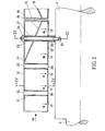
- FIG. 2 shows a longitudinal sectional illustration of an exemplary embodiment of the cooling medium distribution body 12, but instead of the continuous opening 16 shown in FIG. 1 in the form of a longitudinal gap, in the part 12 ′ of the cooling medium distribution body 12 facing the central body, several in FIG. 2 the fastening mechanism of the coolant distribution body 12 resulting interruptions of the openings 17 are formed.
- the direction of flow of the cooling medium is indicated by arrow 18.
- the effective cross section of the openings 17 is varied in the direction of the flow of the cooling medium up to the center of the machine.
- inclined guiding devices 19 are arranged, which at the same time serve to mechanically stiffen the cooling medium distribution body 12.
- a plurality of bores 20 are made in the cooling medium distribution body 12, into which sleeves 21 are inserted and solidified. These sleeves 21 are used for the passage of retaining bolts 22 which are screwed into bores 23 of the central body of the rotor 1.
- Spacer sleeves 25 are located between the cooling medium body 12 and the central body of the rotor 1, so that the space between the part 12 ′ of the cooling medium distribution body 12 facing the central body 1 and the central body 1 can be selectively spaced.
- the spacer sleeves 25 are made of a metallic material, e.g. austenitic steel.
- a cooling medium distribution body 12 is drawn, which extends from one end face of the rotor to the center of the rotor, symmetrically to this, a second cooling medium distribution body 12 is arranged in the right half of the rotor, which is only indicated in Fig. 2.
- FIG. 3 shows section III from FIG. 2.
- the same reference numerals apply to the same parts as in FIGS. 1 and 2.
- the spatial arrangement of the cooling medium distribution body 12 in the pole gap 11 is visible.
- the cooling medium distribution body 12 is spaced in the lower part 12 ′ by spacer sleeves 25 from the central body of the rotor 1 and the side surfaces 13 are spaced from the side surfaces of the pole coils 5 by winding supports 26.
- the winding supports 26 are preferably made of plastic. 3 shows how the design of the coolant distribution body 12 can be adapted to that of the pole cores 3, the pole shoes 4 and the pole coil 5.
- the cooling medium distribution bodies 12 consist of austenitic steel, aluminum alloy or glass fiber-reinforced plastic.
- the guide device 19 is made of the same material.
- FIG. 4 corresponds to the section IT of FIG. 2.
- pole shoes 4 and pole coils 5 a partial cross section through a rotor was shown in FIG. 4, the pole shoes 4 of which are considerably shorter than in FIG. 3, and the pole coils 5 protrude beyond the pole piece 4.
- the coolant distribution body 12 has another embodiment as shown in FIG. 3 in order to ensure optimal coolant guidance for this type of machine deliver.
- 4 shows the section through an opening 17 from which the cooling medium emerges from the cooling medium distribution body 12 and the direction of flow of the cooling medium along the side surfaces of the pole coils 5, which is shown in the direction of the arrows with the reference number 18.
- the mode of operation of the illustrated example of the cooling medium distribution body 12 is as follows:
- the cooling medium flow generated by the axial fans 6 located on the right and left outside of the rotor body is directed from the end faces of the rotor in the axial direction, according to the arrows 18 shown in FIG. 1, into the cooling medium distribution body 12 funded.
- the cooling medium flows through the cooling medium distribution body 12 on both sides in the longitudinal direction parallel to the machine axis and is deflected towards the central body of the rotor 1, passes through the openings 16 which are located in the part 12 'of the cooling medium distribution body 12 facing the central body and is introduced into the columns 14 that space the side faces 13 of the cooling medium distribution body 12 and the side faces of the pole cores 3 and the pole coils 5.
- the axial flow direction of the cooling medium within the cooling medium distribution body 12 is deflected into a radial flow according to the arrows 18 shown.
- This radial cooling medium flow is continuously guided along the side surfaces of the pole coils 5 or the pole cores 3 in all zones of the rotor and, with a corresponding adjustment of the coolant quantity and speed depending on the type of machine, enables optimal dissipation of the heat loss from the pole coils 5 or from the pole cores 3 in all parts of the rotor.
Landscapes
- Engineering & Computer Science (AREA)
- Power Engineering (AREA)
- Motor Or Generator Cooling System (AREA)
- Iron Core Of Rotating Electric Machines (AREA)
- Compression-Type Refrigeration Machines With Reversible Cycles (AREA)
- Superconductors And Manufacturing Methods Therefor (AREA)
- Turbine Rotor Nozzle Sealing (AREA)
- Separation Using Semi-Permeable Membranes (AREA)
Abstract
Description
- Die Erfindung bezieht sich auf eine axialbelüftete elektrische Maschine mit einem Rotor mit ausgeprägten Polen, wobei in den Pollücken in axialer Richtung sich erstreckende Kühlmediumverteilkörper angeordnet sind. Eine derartige Maschine ist aus der deutschen Auslegeschrift 1 085 606 bekannt.
- Zweck der Kühlung von elektrischen Maschinen ist es, die Wärmeverluste so abzuführen, dass beim Nennbetrieb die Erwärmung in den einzelnen Teilen der elektrischen Maschine die gegebenen Grenztemperaturen nicht überschreitet.
- Schenkelpolmaschinen, die ihr Kühlmedium symmetrisch von beiden Seiten zugeführt erhalten, weisen bekanntlich in der Mitte höhere Temperaturen an den Polwicklungen auf als in der Nähe der Stirnseiten, kurz nach Eintritt des Kühlmediums in die Pollücken. Dies wird dadurch verursacht, dass das Kühlmedium über den Luftspalt zwischen Rotor und Stator über die axiale Länge der Maschine gesehen, in den letztgenannten übertritt. Dadurch nimmt die Geschwindigkeit in den Pollücken bis zur Mitte der Maschine ständig ab, so dass mit den kleinen Kühlmediumgeschwindigkeiten keine ausreichende zur Verlustabführung genügende Wärmeübergangszahl mehr erreicht wird.
- Bei den aus der DE-AS 1 085 606 bekannten in den Pollücken zum Einbau gelangten Verdrängungskörpern wird zwar das Kühlmedium gezielt an die zu kühlenden Flächen, insbesondere Polspulen geführt und dabei die Geschwindigkeit des radial in die Pollücken einströmenden Kühlmediums und damit die Wärmeübergangszahl des Kühlmediums angehoben, aber diese Massnahme wird erkauft durch einen höheren statischen Druckabfall im Maschinenkühlkreis und als Folge daraus resultiert eine erhöhte Leistung für die Kühlstromumwälzung und damit gleichzeitig eine Erhöhung der Ventilatorantriebsleistung. In ungünstigen Fällen könnte es sogar dazu führen, dass zu anderen Druckerzeugern übergegangen werden muss.
- Hier wird die Erfindung Abhilfe schaffen. Die Erfindung, wie sie in den Ansprüchen gekennzeichnet ist, löst die Aufgabe, eine axialbelüftete elektrische Maschine mit einem Rotor mit ausgeprägten Polen zu schaffen, wobei in den Pollücken in axialer Richtung sich erstreckende Kühlmediumverteilkörper angeordnet sind, die eine Kanalisierung des Kühlmittels und ein Anheben der Kühlmittelgeschwindigkeit in optimaler Weise, unter Anpassung an die jeweiligen Kühlverhältnisse, ermöglichen.
- Die Anordnung und Verteilung der Kühlmediumverteilkörper in den Pollücken weisen folgende Vorteile auf:
- - Durch Verkleinerung des Querschnittes an den Polspulenlängsseiten wird die radiale Geschwindigkeit des Kühlmediums derart erhöht, dass eine ausreichende Wärmeübergangszahl zur Wärmeabfuhr erreicht wird;
- - die Einrichtung übernimmt durch ihre Form auch die Funktion des bekannten Pollückengrundkanales, d.h. sie sorgt dafür, dass ein grösserer Anteil des Kühlmediums unvorgewärmt in die Mitte der Maschine strömen kann;
- - der bisher bekannte Pollückengrundkanal wird nicht mehr in dem Ausmass wie bisher ausgeführt werden müssen;
- - es kann die gleiche sekundliche Kühlstrommenge ohne erhöhten statischen Druckabfall der Maschine zugeführt werden, da die Querschnittsverengung am Pollückeneintritt sehr gering ist, da nur die Wandstärke des Kühlmediumverteilkörpers den wirklichen Querschnitt vermindert;
- - es kann sogar zu einem erhöhten Kühlstrom führen, da die Druckerzeugung des Schenkelpolrades verbessert wird.
- Entsprechend Anspruch 2 verlaufen die Seitenflächen der rohrförmigen Kühlmediumverteilkörper parallel zu den zu kühlenden Flanken der Polkörper und der Polspulen, was einfache und übersichtliche Kühlmittelwege ergibt.
- Gemäss Anspruch 3 wird der Spalt zwischen den Seitenflächen der rohrförmigen Kühlmediumverteilkörper und den zu kühlenden Flanken der Polkörper und der Polspulen radial nach aussen verjüngt oder erweitert ausgebildet, und somit ergibt sich die Möglichkeit einer Steuerung der Kühlwirkung in Maschinenlängsrichtung.
- Gemäss Anspruch 4 wird der rohrförmige Kühlmediumverteilkörper mittels Haltebolzen mit dem Zentralkörper des Rotors verbunden und beispielsweise durch Distanzhülsen von den letztgenannten distanziert.
- Nach Anspruch 5 wird der wirksame Querschnitt der Kühlmediumsströmungsöffnungen in axialer Strömungsrichtung im Kühlmediumverteilkörper variiert, eine Massnahme, die entweder allein oder in Kombination des Gegenstandes des Anspruchs 3 ergriffen werden kann und gleichfalls eine gleichmässige Kühlwirkung in Maschinenlängsrichtung bewirkt.
- In den Ansprüchen 6, 7, 8, 9 und 10 wird die konstruktive Ausbildung des Kühlmediumverteilkörpers beschrieben.
- Bei beidseitig ventilierten Maschinen sind nach Anspruch 6 pro Pollücke wenigstens zwei Kühlmediumverteilkörper angeordnet, die sich annähernd symmetrisch von den Stirnseiten bis zur Rotormitte erstrecken und dort offen oder teilweise oder ganz geschlossen sind und die nach Anspruch 7 Leiteinrichtungen aufweisen.
- Alternativ zu Anspruch 6 und 7 betrifft Anspruch 8 eine einstückige Ausführungsform eines Kühlmediumverteilkörpers, der nach Anspruch 9 im rotormittigen Abschnitt teilweise oder ganz durch eine Trennwand separiert ist, die nach Anspruch 10 als Leiteinrichtung ausgebildet ist.
- Die Erfindung wird nachstehend anhand eines in der Zeichnung dargestellten Ausführungsbeispieles näher erläutert.
- In der Zeichnung zeigt:
- Fig. 1 eine perspektivische, teilweise Schnittdarstellung des erfindungsgemässen Rotors,
- Fig. 2 einen Längsschnitt durch einen Kühlmediumverteilkörper,
- Fig. 3 einen teilweisen Querschnitt durch einen erfindungsgemässen Rotor gemäss Fig. 1 und 2
- Fig. 4 einen teilweisen Querschnitt durch einen erfindungsgemässen Rotor gemäss Fig. 1 und 2 jedoch in anderer Schnittlage als Fig. 3 und einer anderen Ausgestaltung der Pole.
- Fig. 1 zeigt einen teilweisen Schnitt eines erfindungsgemässen Rotors.
- Ein Zentralkörper 1 ist auf einer Welle 2 aufgesetzt und mit Polkernen 3 versehen, die Polschuhe 4 und Polspulen 5 tragen. Auf der Rotorwelle 2 ist ein Axialventilator 6 angebracht, der aus einem Schaufelträger 7 und mehreren Ventilatorflügeln 8 besteht. Der Axialventilator 6 befindet sich in einer Oeffnung einer äusseren Ventilatorverschalung. Die Welle 2 ist in einem nicht näher dargestellten Lager, das sich innerhalb des Lagerschildes 10 befindet, drehbar angeordnet.
- Aus Gründen der Uebersichtlichkeit ist in Fig. 1 nur eine Hälfte des Rotors dargestellt, wobei auch das andere Ende des Rotors mit einem Axialventilator versehen ist.
- In diesem Beispiel sind nur zwei Polkerne 3 mit den dazugehörigen Polspulen 5 gezeichnet. In dem Zwischenraum zwischen den Flächen der Polkerne 3 bzw. der Polspulen 5 ist die Pollücke 11 dargestellt, in der sich ein Kühlmediumverteilkörper 12 befindet. Seine Seitenflächen 13 verlaufen parallel zu den zu kühlenden Seitenflächen der Polkerne 3 bzw. der Polspulen 5.
- Auf diese Weise werden Spalten 14 zwischen den Seitenflächen 13 des Kühlmediumverteilkörpers 12 und den Seitenflächen der Polkerne 3 bzw. der Polspulen 5 ausgebildet.
- Der Kühlmediumverteilkörper 12 ist in Richtung zum Axialventilator 6 und zum Zentralkörper 1 hin geöffnet.
- Demgegenüber ist er am anderen Ende, im rotormittigen Abschnitt mit einer Abschlussplatte 15 verschlossen, die in Fig. 1 nicht, jedoch auf den nachfolgenden Zeichnungen dargestellt ist.
- Aus Gründen der Uebersichtlichkeit sind in Fig. 1 keine Befestigungselemente des Kühlmediumverteilkörpers 12 gezeigt, diese werden jedoch in den folgenden Zeichnungen näher dargestellt. Mit Bezugsziffer 16 werden die Oeffnungen bezeichnet, die im Teil des Kühlmediumverteilkörpers 12' der dem Zentralkörper 1 des Rotors zugewandt ist, angebracht sind.
- Fig. 2 zeigt eine Längsschnittdarstellung einer beispielsweisen Ausführungsform des Kühlmediumverteilkörpers 12, wobei jedoch anstelle der in Fig. 1 gezeigten, ununterbrochenen Oeffnung 16 in Form eines Längsspaltes, in dem den Zentralkörper zugewandten Teils 12' des Kühlmediumverteilkörpers 12, in Fig. 2 mehrere, durch den Befestigungsmechanismus des Kühlmediumverteilkörpers 12 sich ergebende Unterbrechungen der Oeffnungen 17 ausgebildet sind. Mit Pfeil 18 ist die Strömungsrichtung des Kühlmediums angegeben.
- Wie aus Fig. 2 ersichtlich ist, wird der wirksame Querschnitt der Oeffnungen 17 in der Richtung der Strömung des Kühlmediums, bis zur Maschinenmitte variiert.
- Als weitere Massnahme zur Druck- bzw. Geschwindigkeitsstabilisierung des Kühlmediums im rotormittigen Teil sind schräg verlaufende Leiteinrichtungen 19 angeordnet, die gleichzeitig der mechanischen Versteifung des Kühlmediumverteilkörpers 12 dienen.
- Für die Befestigung der Kühlmediumverteilkörper 12 sind im Kühlmediumverteilkörper 12 mehrere Bohrungen 20 angebracht, in die Hülsen 21 eingesetzt und verfestigt sind. Diese Hülsen 21 dienen für den Durchgang von Haltebolzen 22, die in Bohrungen 23 des Zentralkörpers des Rotors 1 eingeschraubt sind.
- Im dargestellten Beispiel ist nur ein Haltebolzen 22 gezeichnet. Für die Befestigung der Kühlmediumverteilkörper 12 an den Haltebolzen 22 dient je eine Mutter 24.
- Zwischen dem Kühlmediumkörper 12 und dem Zentralkörper des Rotors 1 befinden sich Distanzhülsen 25, so dass der Raum zwischen dem den Zentralkörper 1 zugewandten Teil 12' des Kühlmediumverteilkörpers 12 und dem Zentralkörper 1 wählbar distanziert werden kann. Die Distanzhülsen 25 bestehen aus einem metallischen Werkstoff, z.B. austenitischer Stahl.
- In Fig. 2 ist lediglich ein Kühlmediumverteilkörper 12 gezeichnet, der sich von der einen Stirnseite des Rotors bis zur Rotormitte erstreckt, symmetrisch dazu ist in der rechten Rotorhälfte ein zweiter Kühlmediumverteilkörper 12 angeordnet, der in Fig. 2 nur andeutungsweise dargestellt ist.
- Fig. 3 zeigt den Schnitt III aus Fig. 2. Für die Fig. 3 gelten für dieselben Teile die gleichen Bezugsziffern wie in Fig. 1 und 2.
- Die räumliche Anordnung des Kühlmediumverteilkörpers 12 in der Pollücke 11 ist sichtbar. Der Kühlmediumverteilkörper 12 ist im unteren Teil 12' durch Distanzhülsen 25 vom Zentralkörper des Rotors 1 beabstandet und die Seitenflächen 13 werden durch Wicklungsabstützungen 26 von den Seitenflächen der Polspulen 5 distanziert. Die Wicklungsabstützungen 26 bestehen vorzugsweise aus Kunststoff. Aus Fig. 3 ist ersichtlich, wie die Ausbildungsform des Kühlmediumverteilkörpers 12 derjenigen der Polkerne 3, der Polschuhe 4 und Polspule 5 angepasst werden kann.
- Die Kühlmediumverteilkörper 12 bestehen in diesem Beispiel aus austenitischem Stahl, aus Aluminiumlegierung oder aus glasfaserverstärktem Kunststoff. Die Leiteinrichtung 19 besteht aus dem gleichen Material.
- Eine ähnliche erfindungsgemässe, beispielsweise Ausführungsform ist in Fig. 4 dargestellt, die dem Schnitt IT der Fig. 2 entspricht.
- Um die Anpassungsmöglichkeit des Kühlmediumverteilkörpers 12 an unterschiedliche konstruktive Ausführungsformen der Polkerne 3, Polschuhe 4 und Polspulen 5 zu zeigen, wurde in Fig. 4 ein Teilquerschnitt durch einen Rotor dargestellt, dessen Polschuhe 4 wesentlich kürzer sind als in Fig. 3, und die Polspulen 5 über den Polschuh 4 hinausragen.
- In diesem Fall hat der Kühlmediumverteilkörper 12 eine andere Ausführungsform wie in Fig. 3 dargestellt, um für diese Maschinenart eine optimale Kühlmittelführung sicherzustellen. In Fig. 4 sieht man den Schnitt durch eine Oeffnung 17, aus der das Kühlmedium aus dem Kühlmediumverteilkörper 12 austritt und die Strömungsrichtung des Kühlmediums entlang der Seitenflächen der Polspulen 5, die in Richtung der Pfeile mit der Bezugsziffer 18 dargestellt ist.
- Die Wirkungsweise des dargestellten Beispieles des Kühlmediumverteilkörpers 12 ist wie folgt: Der durch die rechts und links ausserhalb des Rotorkörpers befindlichen Axialventilatoren 6 erzeugte Kühlmediumstrom wird von den Stirnseiten des Rotors, in axialer Richtung, entsprechend der dargestellten Pfeile 18 in Fig. 1, in die Kühlmediumverteilkörper 12 gefördert. Das Kühlmedium durchströmt beidseitig die Kühlmediumverteilkörper 12 in Längsrichtung parallel zur Maschinenachse und wird zum Zentralkörper des Rotors 1 hin abgelenkt, tritt durch die Oeffnungen 16, die sich in dem, dem Zentralkörper zugewandte Teil 12' des Kühlmediumverteilkörpers 12 befinden und wird in die Spalten 14 hineingeführt, die die Seitenflächen 13 des Kühlmediumverteilkörpers 12 und die Seitenflächen der Polkerne 3 bzw. der Polspulen 5 beabstanden. Dabei wird die axiale Strömungsrichtung des Kühlmediums innerhalb der Kühlmediumverteilkörper 12 in eine radiale Strömung entsprechend der dargestellten Pfeile 18 umgelenkt. Dieser radiale Kühlmediumstrom wird kontinuierlich an den Seitenflächen der Polspulen 5 bzw. der Polkerne 3 in allen Zonen des Rotors entlanggeführt und ermöglicht bei entsprechender Anpassung der Kühlmittelmenge- und Geschwindigkeit je nach Maschinentyp eine optimale Abführung der Verlustwärme von den Polspulen 5 bzw. von den Polkernen 3 in allen Teilen des Rotors.
-
- 1 Zentralkörper des Rotors
- 2 Welle des Rotors
- 3 Polkerne
- 4 Polschuhe
- 5 Polspulen
- 6 Axialventilator
- 7 Schaufelträger
- 8 Ventilatorflügel
- 9 Aeussere Ventilatorverschalung
- 10 Lagerschild
- 11 Pollücke
- 12 Kühlmediumverteilkörper
- 12' Teil des Kühlmediumverteilkörpers, der dem Zentralkörper des Rotors zugewandt ist
- 13 Seitenflächen des Kühlmediumverteilkörpers
- 14 Spalten
- 15 Abschlussplatte
- 16 Oeffnungen (Längsspalt)
- 17 Oeffnungen (unterbrochene)
- 18 Pfeil für Strömungsrichtung des Kühlmediums
- 19 Leiteinrichtung
- 20 Bohrungen im Kühlmediumverteilkörper
- 21 Hülsen
- 22 Haltebolzen
- 23 Bohrungen im Zentralkörper
- 24 Mutter
- 25 Distanzhülsen
- 26 Wicklungsabstützung
Claims (10)
Priority Applications (1)
| Application Number | Priority Date | Filing Date | Title |
|---|---|---|---|
| AT81201009T ATE13374T1 (de) | 1980-11-17 | 1981-09-10 | Kuehlmediumsverteilkoerper. |
Applications Claiming Priority (2)
| Application Number | Priority Date | Filing Date | Title |
|---|---|---|---|
| CH8494/80 | 1980-11-17 | ||
| CH849480 | 1980-11-17 |
Publications (2)
| Publication Number | Publication Date |
|---|---|
| EP0052383A1 true EP0052383A1 (de) | 1982-05-26 |
| EP0052383B1 EP0052383B1 (de) | 1985-05-15 |
Family
ID=4341167
Family Applications (1)
| Application Number | Title | Priority Date | Filing Date |
|---|---|---|---|
| EP81201009A Expired EP0052383B1 (de) | 1980-11-17 | 1981-09-10 | Kühlmediumsverteilkörper |
Country Status (6)
| Country | Link |
|---|---|
| EP (1) | EP0052383B1 (de) |
| AT (1) | ATE13374T1 (de) |
| BR (1) | BR8107375A (de) |
| CA (1) | CA1181118A (de) |
| DE (1) | DE3170511D1 (de) |
| NO (1) | NO156550C (de) |
Cited By (8)
| Publication number | Priority date | Publication date | Assignee | Title |
|---|---|---|---|---|
| DE3314426A1 (de) * | 1982-04-22 | 1983-10-27 | Mitsubishi Denki K.K., Tokyo | Schenkelpollaeufer fuer eine elektrische rotationsmaschine |
| EP0198095A1 (de) * | 1985-04-11 | 1986-10-22 | Nippondenso Co., Ltd. | Rotor eines Generators montiert auf einem Fahrzeug |
| EP0680130A1 (de) * | 1994-04-29 | 1995-11-02 | Abb Industrie | Elektrische Synchronmaschine mit glatten Polen und konstantem Luftspalt |
| USRE36038E (en) * | 1983-12-19 | 1999-01-12 | Denso Corporation | Rotor of alternator mounted on vehicle |
| GB2410380A (en) * | 2000-11-30 | 2005-07-27 | Richard Julius Gozdawa | Air-cooled electric generator or motor, eg of gas turbomachinery |
| EP1564865A1 (de) * | 2004-02-12 | 2005-08-17 | Siemens Aktiengesellschaft | Schenkelpolmaschine mit mindestens einer Polspule |
| EP2690756A3 (de) * | 2012-07-27 | 2017-12-20 | Andreas Stihl AG & Co. KG | Elektrischer Antriebsmotor für ein Arbeitsgerät |
| EP4492641A1 (de) * | 2023-07-11 | 2025-01-15 | Abb Schweiz Ag | Elektrische drehmaschine mit spulenträgern |
Families Citing this family (2)
| Publication number | Priority date | Publication date | Assignee | Title |
|---|---|---|---|---|
| JPS6036701B2 (ja) * | 1979-12-14 | 1985-08-22 | 株式会社デンソー | 車両用交流発電機 |
| CA2010670C (en) * | 1990-02-22 | 1997-04-01 | James H. Dymond | Salient pole rotor for a dynamoelectric machine |
Citations (5)
| Publication number | Priority date | Publication date | Assignee | Title |
|---|---|---|---|---|
| DE1191475B (de) * | 1961-07-31 | 1965-04-22 | Licentia Gmbh | Anordnung zur Fuehrung des Kuehlmediums in den Polluecken von Schenkelpollaeufern elektrischer Maschinen |
| DE1225288B (de) * | 1962-07-26 | 1966-09-22 | Licentia Gmbh | Anordnung zur Fuehrung des Kuehlmediums in den Polluecken von Schenkelpollaeufern elektrischer Maschinen |
| US3514647A (en) * | 1968-09-30 | 1970-05-26 | Gen Electric | Cooling arrangement for dynamoelectric machines |
| US3846651A (en) * | 1973-06-12 | 1974-11-05 | Westinghouse Electric Corp | Dynamoelectric machine ventilating system |
| FR2433255A1 (fr) * | 1978-08-11 | 1980-03-07 | Cem Comp Electro Mec | Rotor de machine electrique a poles saillants |
-
1981
- 1981-09-10 AT AT81201009T patent/ATE13374T1/de active
- 1981-09-10 DE DE8181201009T patent/DE3170511D1/de not_active Expired
- 1981-09-10 EP EP81201009A patent/EP0052383B1/de not_active Expired
- 1981-11-10 NO NO813807A patent/NO156550C/no unknown
- 1981-11-13 BR BR8107375A patent/BR8107375A/pt unknown
- 1981-11-16 CA CA000390136A patent/CA1181118A/en not_active Expired
Patent Citations (5)
| Publication number | Priority date | Publication date | Assignee | Title |
|---|---|---|---|---|
| DE1191475B (de) * | 1961-07-31 | 1965-04-22 | Licentia Gmbh | Anordnung zur Fuehrung des Kuehlmediums in den Polluecken von Schenkelpollaeufern elektrischer Maschinen |
| DE1225288B (de) * | 1962-07-26 | 1966-09-22 | Licentia Gmbh | Anordnung zur Fuehrung des Kuehlmediums in den Polluecken von Schenkelpollaeufern elektrischer Maschinen |
| US3514647A (en) * | 1968-09-30 | 1970-05-26 | Gen Electric | Cooling arrangement for dynamoelectric machines |
| US3846651A (en) * | 1973-06-12 | 1974-11-05 | Westinghouse Electric Corp | Dynamoelectric machine ventilating system |
| FR2433255A1 (fr) * | 1978-08-11 | 1980-03-07 | Cem Comp Electro Mec | Rotor de machine electrique a poles saillants |
Cited By (14)
| Publication number | Priority date | Publication date | Assignee | Title |
|---|---|---|---|---|
| DE3314426A1 (de) * | 1982-04-22 | 1983-10-27 | Mitsubishi Denki K.K., Tokyo | Schenkelpollaeufer fuer eine elektrische rotationsmaschine |
| USRE36038E (en) * | 1983-12-19 | 1999-01-12 | Denso Corporation | Rotor of alternator mounted on vehicle |
| EP0198095A1 (de) * | 1985-04-11 | 1986-10-22 | Nippondenso Co., Ltd. | Rotor eines Generators montiert auf einem Fahrzeug |
| EP0680130A1 (de) * | 1994-04-29 | 1995-11-02 | Abb Industrie | Elektrische Synchronmaschine mit glatten Polen und konstantem Luftspalt |
| FR2719423A1 (fr) * | 1994-04-29 | 1995-11-03 | Abb Ind | Machine électrique synchrone à pôles lisses et à entrefer constant. |
| US5563460A (en) * | 1994-04-29 | 1996-10-08 | Abb Industrie | Electrical synchronous machine with smooth poles and with a constant air gap |
| GB2410380A (en) * | 2000-11-30 | 2005-07-27 | Richard Julius Gozdawa | Air-cooled electric generator or motor, eg of gas turbomachinery |
| GB2410380B (en) * | 2000-11-30 | 2005-08-31 | Richard Julius Gozdawa | Rotor for electric generator or motor |
| EP1564865A1 (de) * | 2004-02-12 | 2005-08-17 | Siemens Aktiengesellschaft | Schenkelpolmaschine mit mindestens einer Polspule |
| WO2005078898A1 (de) * | 2004-02-12 | 2005-08-25 | Siemens Aktiengesellschaft | Schenkelpolmaschine mit mindestens einer polspule |
| CN100588080C (zh) * | 2004-02-12 | 2010-02-03 | 西门子公司 | 具有至少一个极线圈的凸极电机 |
| US7915771B2 (en) | 2004-02-12 | 2011-03-29 | Siemens Aktiengesellschaft | Salient-pole machine comprising at least one field coil |
| EP2690756A3 (de) * | 2012-07-27 | 2017-12-20 | Andreas Stihl AG & Co. KG | Elektrischer Antriebsmotor für ein Arbeitsgerät |
| EP4492641A1 (de) * | 2023-07-11 | 2025-01-15 | Abb Schweiz Ag | Elektrische drehmaschine mit spulenträgern |
Also Published As
| Publication number | Publication date |
|---|---|
| EP0052383B1 (de) | 1985-05-15 |
| DE3170511D1 (en) | 1985-06-20 |
| NO156550C (no) | 1987-10-07 |
| CA1181118A (en) | 1985-01-15 |
| NO813807L (no) | 1982-05-18 |
| BR8107375A (pt) | 1982-08-10 |
| ATE13374T1 (de) | 1985-06-15 |
| NO156550B (no) | 1987-06-29 |
Similar Documents
| Publication | Publication Date | Title |
|---|---|---|
| DE102008064495B3 (de) | Elektrische Maschine mit mehreren Kühlströmen und Kühlverfahren | |
| DE10019230B4 (de) | Linearmotor | |
| DE102008064498A1 (de) | Elektrische Maschine mit radial versetztem Kühlstrom und Kühlverfahren | |
| DE102013020332A1 (de) | Elektrische Maschine, insbesondere Asynchronmaschine | |
| EP3046225A1 (de) | Elektrische rotierende Maschine mit einseitiger Kühlung und Verfahren zur einseitigen Kühlung | |
| EP2930827B1 (de) | Elektrische Maschine mit Strömungskühlung | |
| WO2017032538A1 (de) | Kühlsystem für eine elektrische maschine | |
| DE1939184A1 (de) | Anordnung zur Kuehlung der Rotoren elektrischer Maschinen,insbesondere elektrischer Kleinmotoren | |
| DE202011001558U1 (de) | Elektrische Maschine | |
| EP0052383B1 (de) | Kühlmediumsverteilkörper | |
| WO2023066648A1 (de) | Stator für eine elektrische maschine eines kraftfahrzeugs sowie elektrische maschine | |
| DE3101423C2 (de) | Elektrische Maschine | |
| DE3314426C2 (de) | Schenkelpolläufer für eine elektrische Maschine | |
| DE102023204449A1 (de) | Rotoranordnung zur verbesserten Kühlung eines Rotors | |
| EP4331095B1 (de) | Elektrische maschine | |
| DE102008044502A1 (de) | Generator mit einem Kühlstromverzweigungselement und Verfahren zur Steuerung einer Kühlströmung | |
| EP0415057B1 (de) | Anordnung zur Führung des Kühlmediums in Schenkelpolmaschinen | |
| EP0172397A1 (de) | Elektrische Maschine mit indirekt gekühlter Statorwicklung | |
| DE112016002394T5 (de) | Rotierende elektrische maschine | |
| WO2025021418A1 (de) | Axialflussmaschine mit einem rotor | |
| CH648439A5 (en) | Rotating electrical machine having a stator with radially arranged cooling channels with spacer webs | |
| WO2024184096A1 (de) | Elektrische maschine für ein kraftfahrzeug | |
| DE1191475B (de) | Anordnung zur Fuehrung des Kuehlmediums in den Polluecken von Schenkelpollaeufern elektrischer Maschinen | |
| DE102023119260A1 (de) | Rotor für eine elektrische Traktionsmaschine, Traktionsmaschine sowie Kraftfahrzeug | |
| AT233664B (de) | Anordnung zur Führung des Kühlmediums an Schenkelpolläufern elektrischer Maschinen |
Legal Events
| Date | Code | Title | Description |
|---|---|---|---|
| PUAI | Public reference made under article 153(3) epc to a published international application that has entered the european phase |
Free format text: ORIGINAL CODE: 0009012 |
|
| AK | Designated contracting states |
Designated state(s): AT CH DE GB SE |
|
| 17P | Request for examination filed |
Effective date: 19820927 |
|
| GRAA | (expected) grant |
Free format text: ORIGINAL CODE: 0009210 |
|
| AK | Designated contracting states |
Designated state(s): AT CH DE GB LI SE |
|
| REF | Corresponds to: |
Ref document number: 13374 Country of ref document: AT Date of ref document: 19850615 Kind code of ref document: T |
|
| REF | Corresponds to: |
Ref document number: 3170511 Country of ref document: DE Date of ref document: 19850620 |
|
| PLBE | No opposition filed within time limit |
Free format text: ORIGINAL CODE: 0009261 |
|
| STAA | Information on the status of an ep patent application or granted ep patent |
Free format text: STATUS: NO OPPOSITION FILED WITHIN TIME LIMIT |
|
| 26N | No opposition filed | ||
| PG25 | Lapsed in a contracting state [announced via postgrant information from national office to epo] |
Ref country code: SE Effective date: 19890911 |
|
| EUG | Se: european patent has lapsed |
Ref document number: 81201009.8 Effective date: 19900521 |
|
| PGFP | Annual fee paid to national office [announced via postgrant information from national office to epo] |
Ref country code: GB Payment date: 19990813 Year of fee payment: 19 |
|
| PGFP | Annual fee paid to national office [announced via postgrant information from national office to epo] |
Ref country code: CH Payment date: 19990816 Year of fee payment: 19 |
|
| PGFP | Annual fee paid to national office [announced via postgrant information from national office to epo] |
Ref country code: DE Payment date: 19990820 Year of fee payment: 19 |
|
| PGFP | Annual fee paid to national office [announced via postgrant information from national office to epo] |
Ref country code: AT Payment date: 19990824 Year of fee payment: 19 |
|
| PG25 | Lapsed in a contracting state [announced via postgrant information from national office to epo] |
Ref country code: GB Free format text: LAPSE BECAUSE OF NON-PAYMENT OF DUE FEES Effective date: 20000910 Ref country code: AT Free format text: LAPSE BECAUSE OF NON-PAYMENT OF DUE FEES Effective date: 20000910 |
|
| PG25 | Lapsed in a contracting state [announced via postgrant information from national office to epo] |
Ref country code: LI Free format text: LAPSE BECAUSE OF NON-PAYMENT OF DUE FEES Effective date: 20000930 Ref country code: CH Free format text: LAPSE BECAUSE OF NON-PAYMENT OF DUE FEES Effective date: 20000930 |
|
| GBPC | Gb: european patent ceased through non-payment of renewal fee |
Effective date: 20000910 |
|
| REG | Reference to a national code |
Ref country code: CH Ref legal event code: PL |
|
| PG25 | Lapsed in a contracting state [announced via postgrant information from national office to epo] |
Ref country code: DE Free format text: LAPSE BECAUSE OF NON-PAYMENT OF DUE FEES Effective date: 20010601 |