EP0052383A1 - Distributeur de réfrigérant - Google Patents
Distributeur de réfrigérant Download PDFInfo
- Publication number
- EP0052383A1 EP0052383A1 EP81201009A EP81201009A EP0052383A1 EP 0052383 A1 EP0052383 A1 EP 0052383A1 EP 81201009 A EP81201009 A EP 81201009A EP 81201009 A EP81201009 A EP 81201009A EP 0052383 A1 EP0052383 A1 EP 0052383A1
- Authority
- EP
- European Patent Office
- Prior art keywords
- cooling medium
- pole
- rotor
- coolant
- distribution body
- Prior art date
- Legal status (The legal status is an assumption and is not a legal conclusion. Google has not performed a legal analysis and makes no representation as to the accuracy of the status listed.)
- Granted
Links
- 239000002826 coolant Substances 0.000 title claims abstract description 88
- 238000001816 cooling Methods 0.000 claims description 9
- 230000000694 effects Effects 0.000 claims description 3
- 238000005192 partition Methods 0.000 claims description 3
- 238000009423 ventilation Methods 0.000 claims 3
- 230000015572 biosynthetic process Effects 0.000 claims 1
- 230000003716 rejuvenation Effects 0.000 claims 1
- 125000006850 spacer group Chemical group 0.000 description 5
- 238000004804 winding Methods 0.000 description 4
- 229910000831 Steel Inorganic materials 0.000 description 2
- 230000003068 static effect Effects 0.000 description 2
- 239000010959 steel Substances 0.000 description 2
- 229910000838 Al alloy Inorganic materials 0.000 description 1
- 230000004323 axial length Effects 0.000 description 1
- 239000000969 carrier Substances 0.000 description 1
- 230000007423 decrease Effects 0.000 description 1
- 238000006073 displacement reaction Methods 0.000 description 1
- 239000011152 fibreglass Substances 0.000 description 1
- 230000017525 heat dissipation Effects 0.000 description 1
- 238000010438 heat treatment Methods 0.000 description 1
- 239000000463 material Substances 0.000 description 1
- 239000007769 metal material Substances 0.000 description 1
- 239000004033 plastic Substances 0.000 description 1
- 229920003023 plastic Polymers 0.000 description 1
- 230000000087 stabilizing effect Effects 0.000 description 1
Images


Classifications
-
- H—ELECTRICITY
- H02—GENERATION; CONVERSION OR DISTRIBUTION OF ELECTRIC POWER
- H02K—DYNAMO-ELECTRIC MACHINES
- H02K3/00—Details of windings
- H02K3/04—Windings characterised by the conductor shape, form or construction, e.g. with bar conductors
- H02K3/24—Windings characterised by the conductor shape, form or construction, e.g. with bar conductors with channels or ducts for cooling medium between the conductors
-
- H—ELECTRICITY
- H02—GENERATION; CONVERSION OR DISTRIBUTION OF ELECTRIC POWER
- H02K—DYNAMO-ELECTRIC MACHINES
- H02K1/00—Details of the magnetic circuit
- H02K1/06—Details of the magnetic circuit characterised by the shape, form or construction
- H02K1/22—Rotating parts of the magnetic circuit
- H02K1/32—Rotating parts of the magnetic circuit with channels or ducts for flow of cooling medium
- H02K1/325—Rotating parts of the magnetic circuit with channels or ducts for flow of cooling medium between salient poles
Definitions
- the invention relates to an axially ventilated electrical machine with a rotor with pronounced poles, cooling medium distribution bodies extending in the axial direction being arranged in the pole gaps.
- Such a machine is known from the German patent application 1 085 606.
- cooling electrical machines The purpose of cooling electrical machines is to dissipate the heat losses in such a way that the heating in the individual parts of the electrical machine does not exceed the given limit temperatures during nominal operation.
- Salient pole machines which receive their cooling medium symmetrically from both sides, are known to have higher temperatures at the pole windings in the middle than near the end faces, shortly after the cooling medium enters the pole gaps. This is caused by the fact that the cooling medium, seen through the air gap between the rotor and stator over the axial length of the machine, passes into the latter. As a result, the speed in the pole gaps decreases continuously up to the center of the machine, so that the small cooling medium speeds up sufficient heat transfer coefficient to dissipate losses is no longer achieved.
- the cooling medium is guided specifically to the surfaces to be cooled, in particular pole coils, and the speed of the cooling medium flowing radially into the pole gaps and thus the heat transfer coefficient of the cooling medium are increased , but this measure is bought by a higher static pressure drop in the machine cooling circuit and as a result of this results in an increased performance for the cooling current circulation and thus an increase in the fan drive performance. In unfavorable cases, it could even lead to the need to switch to other pressure generators.
- the invention will remedy this.
- the invention as characterized in the claims, solves the problem of creating an axially ventilated electrical machine with a rotor with pronounced poles, cooling medium distribution bodies extending in the axial direction being arranged in the pole gaps, which channel the coolant and raise the Enable coolant speed in an optimal way, adapting to the respective cooling conditions.
- the side surfaces of the tubular cooling medium distribution body run parallel to the flanks of the pole body and the pole coils to be cooled, which results in simple and clear coolant paths.
- the gap between the side surfaces of the tubular cooling medium distribution body and the flanks of the pole body and the pole coils to be cooled is tapered radially outward or expanded, and thus there is the possibility of controlling the cooling effect in the machine longitudinal direction.
- the tubular cooling medium distribution body is connected to the central body of the rotor by means of retaining bolts and, for example, is spaced from the latter by means of spacer sleeves.
- the effective cross section of the cooling medium flow openings in the axial flow direction in the cooling medium distribution body is varied, a measure that can be taken either alone or in combination of the subject matter of claim 3 and also causes a uniform cooling effect in the machine longitudinal direction.
- At least two cooling medium distribution bodies are arranged per pole gap, which extend approximately symmetrically from the end faces to the center of the rotor and are open or partially or completely closed there and which have guide devices according to claim 7.
- claim 8 relates to a one-piece embodiment of a cooling medium distribution body which, according to claim 9, is partially or completely separated in the rotor-central section by a partition which is designed according to claim 10 as a guide device.
- Fig. 1 shows a partial section of a rotor according to the invention.
- a central body 1 is placed on a shaft 2 and provided with pole cores 3 which carry pole shoes 4 and pole coils 5.
- the axial fan 6 is located in an opening of an outer fan casing.
- the shaft 2 is rotatably arranged in a bearing, not shown, which is located within the bearing plate 10.
- FIG. 1 For the sake of clarity, only one half of the rotor is shown in FIG. 1, the other end of the rotor also being provided with an axial fan.
- pole gap 11 in which a cooling medium distribution body 12 is located, is shown in the space between the surfaces of the pole cores 3 and the pole coils 5. Its side surfaces 13 run parallel to the side surfaces of the pole cores 3 or the pole coils 5 to be cooled.
- columns 14 become between the pages Surfaces 13 of the cooling medium distribution body 12 and the side surfaces of the pole cores 3 and the pole coils 5 are formed.
- the coolant distribution body 12 is open in the direction of the axial fan 6 and the central body 1.
- Reference number 16 denotes the openings which are made in the part of the coolant distribution body 12 'which faces the central body 1 of the rotor.
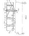
- FIG. 2 shows a longitudinal sectional illustration of an exemplary embodiment of the cooling medium distribution body 12, but instead of the continuous opening 16 shown in FIG. 1 in the form of a longitudinal gap, in the part 12 ′ of the cooling medium distribution body 12 facing the central body, several in FIG. 2 the fastening mechanism of the coolant distribution body 12 resulting interruptions of the openings 17 are formed.
- the direction of flow of the cooling medium is indicated by arrow 18.
- the effective cross section of the openings 17 is varied in the direction of the flow of the cooling medium up to the center of the machine.
- inclined guiding devices 19 are arranged, which at the same time serve to mechanically stiffen the cooling medium distribution body 12.
- a plurality of bores 20 are made in the cooling medium distribution body 12, into which sleeves 21 are inserted and solidified. These sleeves 21 are used for the passage of retaining bolts 22 which are screwed into bores 23 of the central body of the rotor 1.
- Spacer sleeves 25 are located between the cooling medium body 12 and the central body of the rotor 1, so that the space between the part 12 ′ of the cooling medium distribution body 12 facing the central body 1 and the central body 1 can be selectively spaced.
- the spacer sleeves 25 are made of a metallic material, e.g. austenitic steel.
- a cooling medium distribution body 12 is drawn, which extends from one end face of the rotor to the center of the rotor, symmetrically to this, a second cooling medium distribution body 12 is arranged in the right half of the rotor, which is only indicated in Fig. 2.
- FIG. 3 shows section III from FIG. 2.
- the same reference numerals apply to the same parts as in FIGS. 1 and 2.
- the spatial arrangement of the cooling medium distribution body 12 in the pole gap 11 is visible.
- the cooling medium distribution body 12 is spaced in the lower part 12 ′ by spacer sleeves 25 from the central body of the rotor 1 and the side surfaces 13 are spaced from the side surfaces of the pole coils 5 by winding supports 26.
- the winding supports 26 are preferably made of plastic. 3 shows how the design of the coolant distribution body 12 can be adapted to that of the pole cores 3, the pole shoes 4 and the pole coil 5.
- the cooling medium distribution bodies 12 consist of austenitic steel, aluminum alloy or glass fiber-reinforced plastic.
- the guide device 19 is made of the same material.
- FIG. 4 corresponds to the section IT of FIG. 2.
- pole shoes 4 and pole coils 5 a partial cross section through a rotor was shown in FIG. 4, the pole shoes 4 of which are considerably shorter than in FIG. 3, and the pole coils 5 protrude beyond the pole piece 4.
- the coolant distribution body 12 has another embodiment as shown in FIG. 3 in order to ensure optimal coolant guidance for this type of machine deliver.
- 4 shows the section through an opening 17 from which the cooling medium emerges from the cooling medium distribution body 12 and the direction of flow of the cooling medium along the side surfaces of the pole coils 5, which is shown in the direction of the arrows with the reference number 18.
- the mode of operation of the illustrated example of the cooling medium distribution body 12 is as follows:
- the cooling medium flow generated by the axial fans 6 located on the right and left outside of the rotor body is directed from the end faces of the rotor in the axial direction, according to the arrows 18 shown in FIG. 1, into the cooling medium distribution body 12 funded.
- the cooling medium flows through the cooling medium distribution body 12 on both sides in the longitudinal direction parallel to the machine axis and is deflected towards the central body of the rotor 1, passes through the openings 16 which are located in the part 12 'of the cooling medium distribution body 12 facing the central body and is introduced into the columns 14 that space the side faces 13 of the cooling medium distribution body 12 and the side faces of the pole cores 3 and the pole coils 5.
- the axial flow direction of the cooling medium within the cooling medium distribution body 12 is deflected into a radial flow according to the arrows 18 shown.
- This radial cooling medium flow is continuously guided along the side surfaces of the pole coils 5 or the pole cores 3 in all zones of the rotor and, with a corresponding adjustment of the coolant quantity and speed depending on the type of machine, enables optimal dissipation of the heat loss from the pole coils 5 or from the pole cores 3 in all parts of the rotor.
Landscapes
- Engineering & Computer Science (AREA)
- Power Engineering (AREA)
- Motor Or Generator Cooling System (AREA)
- Iron Core Of Rotating Electric Machines (AREA)
- Compression-Type Refrigeration Machines With Reversible Cycles (AREA)
- Superconductors And Manufacturing Methods Therefor (AREA)
- Turbine Rotor Nozzle Sealing (AREA)
- Separation Using Semi-Permeable Membranes (AREA)
Priority Applications (1)
| Application Number | Priority Date | Filing Date | Title |
|---|---|---|---|
| AT81201009T ATE13374T1 (de) | 1980-11-17 | 1981-09-10 | Kuehlmediumsverteilkoerper. |
Applications Claiming Priority (2)
| Application Number | Priority Date | Filing Date | Title |
|---|---|---|---|
| CH8494/80 | 1980-11-17 | ||
| CH849480 | 1980-11-17 |
Publications (2)
| Publication Number | Publication Date |
|---|---|
| EP0052383A1 true EP0052383A1 (fr) | 1982-05-26 |
| EP0052383B1 EP0052383B1 (fr) | 1985-05-15 |
Family
ID=4341167
Family Applications (1)
| Application Number | Title | Priority Date | Filing Date |
|---|---|---|---|
| EP81201009A Expired EP0052383B1 (fr) | 1980-11-17 | 1981-09-10 | Distributeur de réfrigérant |
Country Status (6)
| Country | Link |
|---|---|
| EP (1) | EP0052383B1 (fr) |
| AT (1) | ATE13374T1 (fr) |
| BR (1) | BR8107375A (fr) |
| CA (1) | CA1181118A (fr) |
| DE (1) | DE3170511D1 (fr) |
| NO (1) | NO156550C (fr) |
Cited By (8)
| Publication number | Priority date | Publication date | Assignee | Title |
|---|---|---|---|---|
| DE3314426A1 (de) * | 1982-04-22 | 1983-10-27 | Mitsubishi Denki K.K., Tokyo | Schenkelpollaeufer fuer eine elektrische rotationsmaschine |
| EP0198095A1 (fr) * | 1985-04-11 | 1986-10-22 | Nippondenso Co., Ltd. | Rotor de génératrice monté sur un véhicule |
| EP0680130A1 (fr) * | 1994-04-29 | 1995-11-02 | Abb Industrie | Machine électrique synchrone à pôles lisses et à entrefer constant |
| USRE36038E (en) * | 1983-12-19 | 1999-01-12 | Denso Corporation | Rotor of alternator mounted on vehicle |
| GB2410380A (en) * | 2000-11-30 | 2005-07-27 | Richard Julius Gozdawa | Air-cooled electric generator or motor, eg of gas turbomachinery |
| EP1564865A1 (fr) * | 2004-02-12 | 2005-08-17 | Siemens Aktiengesellschaft | Machine à pole saillant ayant au moins un enroulement autour du pôle |
| EP2690756A3 (fr) * | 2012-07-27 | 2017-12-20 | Andreas Stihl AG & Co. KG | Moteur d'entraînement électrique pour un appareil de travail |
| EP4492641A1 (fr) * | 2023-07-11 | 2025-01-15 | Abb Schweiz Ag | Machine électrique tournante comprenant des supports de bobine |
Families Citing this family (2)
| Publication number | Priority date | Publication date | Assignee | Title |
|---|---|---|---|---|
| JPS6036701B2 (ja) * | 1979-12-14 | 1985-08-22 | 株式会社デンソー | 車両用交流発電機 |
| CA2010670C (fr) * | 1990-02-22 | 1997-04-01 | James H. Dymond | Rotor a pole saillant pour machine dynamoelectrique |
Citations (5)
| Publication number | Priority date | Publication date | Assignee | Title |
|---|---|---|---|---|
| DE1191475B (de) * | 1961-07-31 | 1965-04-22 | Licentia Gmbh | Anordnung zur Fuehrung des Kuehlmediums in den Polluecken von Schenkelpollaeufern elektrischer Maschinen |
| DE1225288B (de) * | 1962-07-26 | 1966-09-22 | Licentia Gmbh | Anordnung zur Fuehrung des Kuehlmediums in den Polluecken von Schenkelpollaeufern elektrischer Maschinen |
| US3514647A (en) * | 1968-09-30 | 1970-05-26 | Gen Electric | Cooling arrangement for dynamoelectric machines |
| US3846651A (en) * | 1973-06-12 | 1974-11-05 | Westinghouse Electric Corp | Dynamoelectric machine ventilating system |
| FR2433255A1 (fr) * | 1978-08-11 | 1980-03-07 | Cem Comp Electro Mec | Rotor de machine electrique a poles saillants |
-
1981
- 1981-09-10 AT AT81201009T patent/ATE13374T1/de active
- 1981-09-10 DE DE8181201009T patent/DE3170511D1/de not_active Expired
- 1981-09-10 EP EP81201009A patent/EP0052383B1/fr not_active Expired
- 1981-11-10 NO NO813807A patent/NO156550C/no unknown
- 1981-11-13 BR BR8107375A patent/BR8107375A/pt unknown
- 1981-11-16 CA CA000390136A patent/CA1181118A/fr not_active Expired
Patent Citations (5)
| Publication number | Priority date | Publication date | Assignee | Title |
|---|---|---|---|---|
| DE1191475B (de) * | 1961-07-31 | 1965-04-22 | Licentia Gmbh | Anordnung zur Fuehrung des Kuehlmediums in den Polluecken von Schenkelpollaeufern elektrischer Maschinen |
| DE1225288B (de) * | 1962-07-26 | 1966-09-22 | Licentia Gmbh | Anordnung zur Fuehrung des Kuehlmediums in den Polluecken von Schenkelpollaeufern elektrischer Maschinen |
| US3514647A (en) * | 1968-09-30 | 1970-05-26 | Gen Electric | Cooling arrangement for dynamoelectric machines |
| US3846651A (en) * | 1973-06-12 | 1974-11-05 | Westinghouse Electric Corp | Dynamoelectric machine ventilating system |
| FR2433255A1 (fr) * | 1978-08-11 | 1980-03-07 | Cem Comp Electro Mec | Rotor de machine electrique a poles saillants |
Cited By (14)
| Publication number | Priority date | Publication date | Assignee | Title |
|---|---|---|---|---|
| DE3314426A1 (de) * | 1982-04-22 | 1983-10-27 | Mitsubishi Denki K.K., Tokyo | Schenkelpollaeufer fuer eine elektrische rotationsmaschine |
| USRE36038E (en) * | 1983-12-19 | 1999-01-12 | Denso Corporation | Rotor of alternator mounted on vehicle |
| EP0198095A1 (fr) * | 1985-04-11 | 1986-10-22 | Nippondenso Co., Ltd. | Rotor de génératrice monté sur un véhicule |
| EP0680130A1 (fr) * | 1994-04-29 | 1995-11-02 | Abb Industrie | Machine électrique synchrone à pôles lisses et à entrefer constant |
| FR2719423A1 (fr) * | 1994-04-29 | 1995-11-03 | Abb Ind | Machine électrique synchrone à pôles lisses et à entrefer constant. |
| US5563460A (en) * | 1994-04-29 | 1996-10-08 | Abb Industrie | Electrical synchronous machine with smooth poles and with a constant air gap |
| GB2410380A (en) * | 2000-11-30 | 2005-07-27 | Richard Julius Gozdawa | Air-cooled electric generator or motor, eg of gas turbomachinery |
| GB2410380B (en) * | 2000-11-30 | 2005-08-31 | Richard Julius Gozdawa | Rotor for electric generator or motor |
| EP1564865A1 (fr) * | 2004-02-12 | 2005-08-17 | Siemens Aktiengesellschaft | Machine à pole saillant ayant au moins un enroulement autour du pôle |
| WO2005078898A1 (fr) * | 2004-02-12 | 2005-08-25 | Siemens Aktiengesellschaft | Machine a poles saillants ayant au moins une bobine de champ |
| CN100588080C (zh) * | 2004-02-12 | 2010-02-03 | 西门子公司 | 具有至少一个极线圈的凸极电机 |
| US7915771B2 (en) | 2004-02-12 | 2011-03-29 | Siemens Aktiengesellschaft | Salient-pole machine comprising at least one field coil |
| EP2690756A3 (fr) * | 2012-07-27 | 2017-12-20 | Andreas Stihl AG & Co. KG | Moteur d'entraînement électrique pour un appareil de travail |
| EP4492641A1 (fr) * | 2023-07-11 | 2025-01-15 | Abb Schweiz Ag | Machine électrique tournante comprenant des supports de bobine |
Also Published As
| Publication number | Publication date |
|---|---|
| EP0052383B1 (fr) | 1985-05-15 |
| DE3170511D1 (en) | 1985-06-20 |
| NO156550C (no) | 1987-10-07 |
| CA1181118A (fr) | 1985-01-15 |
| NO813807L (no) | 1982-05-18 |
| BR8107375A (pt) | 1982-08-10 |
| ATE13374T1 (de) | 1985-06-15 |
| NO156550B (no) | 1987-06-29 |
Similar Documents
| Publication | Publication Date | Title |
|---|---|---|
| DE102008064495B3 (de) | Elektrische Maschine mit mehreren Kühlströmen und Kühlverfahren | |
| DE10019230B4 (de) | Linearmotor | |
| DE102008064498A1 (de) | Elektrische Maschine mit radial versetztem Kühlstrom und Kühlverfahren | |
| DE102013020332A1 (de) | Elektrische Maschine, insbesondere Asynchronmaschine | |
| EP3046225A1 (fr) | Machine électrique rotative avec refroidissement unilatéral et procédé de refroidissement unilatéral | |
| EP2930827B1 (fr) | Machine électrique à refroidissement par convection | |
| WO2017032538A1 (fr) | Système de refroidissement pour machine électrique | |
| DE1939184A1 (de) | Anordnung zur Kuehlung der Rotoren elektrischer Maschinen,insbesondere elektrischer Kleinmotoren | |
| DE202011001558U1 (de) | Elektrische Maschine | |
| EP0052383B1 (fr) | Distributeur de réfrigérant | |
| WO2023066648A1 (fr) | Stator pour une machine électrique d'un véhicule automobile et machine électrique | |
| DE3101423C2 (de) | Elektrische Maschine | |
| DE3314426C2 (de) | Schenkelpolläufer für eine elektrische Maschine | |
| DE102023204449A1 (de) | Rotoranordnung zur verbesserten Kühlung eines Rotors | |
| EP4331095B1 (fr) | Machine électrique | |
| DE102008044502A1 (de) | Generator mit einem Kühlstromverzweigungselement und Verfahren zur Steuerung einer Kühlströmung | |
| EP0415057B1 (fr) | Dispositif pour conduire l'agent de refroidissement dans les machines à pôles saillants | |
| EP0172397A1 (fr) | Machine électrique à enroulement statorique refroidi indirectement | |
| DE112016002394T5 (de) | Rotierende elektrische maschine | |
| WO2025021418A1 (fr) | Machine à flux axial dotée d'un rotor | |
| CH648439A5 (en) | Rotating electrical machine having a stator with radially arranged cooling channels with spacer webs | |
| WO2024184096A1 (fr) | Machine électrique pour véhicule à moteur | |
| DE1191475B (de) | Anordnung zur Fuehrung des Kuehlmediums in den Polluecken von Schenkelpollaeufern elektrischer Maschinen | |
| DE102023119260A1 (de) | Rotor für eine elektrische Traktionsmaschine, Traktionsmaschine sowie Kraftfahrzeug | |
| AT233664B (de) | Anordnung zur Führung des Kühlmediums an Schenkelpolläufern elektrischer Maschinen |
Legal Events
| Date | Code | Title | Description |
|---|---|---|---|
| PUAI | Public reference made under article 153(3) epc to a published international application that has entered the european phase |
Free format text: ORIGINAL CODE: 0009012 |
|
| AK | Designated contracting states |
Designated state(s): AT CH DE GB SE |
|
| 17P | Request for examination filed |
Effective date: 19820927 |
|
| GRAA | (expected) grant |
Free format text: ORIGINAL CODE: 0009210 |
|
| AK | Designated contracting states |
Designated state(s): AT CH DE GB LI SE |
|
| REF | Corresponds to: |
Ref document number: 13374 Country of ref document: AT Date of ref document: 19850615 Kind code of ref document: T |
|
| REF | Corresponds to: |
Ref document number: 3170511 Country of ref document: DE Date of ref document: 19850620 |
|
| PLBE | No opposition filed within time limit |
Free format text: ORIGINAL CODE: 0009261 |
|
| STAA | Information on the status of an ep patent application or granted ep patent |
Free format text: STATUS: NO OPPOSITION FILED WITHIN TIME LIMIT |
|
| 26N | No opposition filed | ||
| PG25 | Lapsed in a contracting state [announced via postgrant information from national office to epo] |
Ref country code: SE Effective date: 19890911 |
|
| EUG | Se: european patent has lapsed |
Ref document number: 81201009.8 Effective date: 19900521 |
|
| PGFP | Annual fee paid to national office [announced via postgrant information from national office to epo] |
Ref country code: GB Payment date: 19990813 Year of fee payment: 19 |
|
| PGFP | Annual fee paid to national office [announced via postgrant information from national office to epo] |
Ref country code: CH Payment date: 19990816 Year of fee payment: 19 |
|
| PGFP | Annual fee paid to national office [announced via postgrant information from national office to epo] |
Ref country code: DE Payment date: 19990820 Year of fee payment: 19 |
|
| PGFP | Annual fee paid to national office [announced via postgrant information from national office to epo] |
Ref country code: AT Payment date: 19990824 Year of fee payment: 19 |
|
| PG25 | Lapsed in a contracting state [announced via postgrant information from national office to epo] |
Ref country code: GB Free format text: LAPSE BECAUSE OF NON-PAYMENT OF DUE FEES Effective date: 20000910 Ref country code: AT Free format text: LAPSE BECAUSE OF NON-PAYMENT OF DUE FEES Effective date: 20000910 |
|
| PG25 | Lapsed in a contracting state [announced via postgrant information from national office to epo] |
Ref country code: LI Free format text: LAPSE BECAUSE OF NON-PAYMENT OF DUE FEES Effective date: 20000930 Ref country code: CH Free format text: LAPSE BECAUSE OF NON-PAYMENT OF DUE FEES Effective date: 20000930 |
|
| GBPC | Gb: european patent ceased through non-payment of renewal fee |
Effective date: 20000910 |
|
| REG | Reference to a national code |
Ref country code: CH Ref legal event code: PL |
|
| PG25 | Lapsed in a contracting state [announced via postgrant information from national office to epo] |
Ref country code: DE Free format text: LAPSE BECAUSE OF NON-PAYMENT OF DUE FEES Effective date: 20010601 |