EP0052385B1 - Dispositif de bague collectrice pour machines électriques - Google Patents
Dispositif de bague collectrice pour machines électriques Download PDFInfo
- Publication number
- EP0052385B1 EP0052385B1 EP81201079A EP81201079A EP0052385B1 EP 0052385 B1 EP0052385 B1 EP 0052385B1 EP 81201079 A EP81201079 A EP 81201079A EP 81201079 A EP81201079 A EP 81201079A EP 0052385 B1 EP0052385 B1 EP 0052385B1
- Authority
- EP
- European Patent Office
- Prior art keywords
- holes
- insulating tubes
- sliprings
- ventilator
- slipring
- Prior art date
- Legal status (The legal status is an assumption and is not a legal conclusion. Google has not performed a legal analysis and makes no representation as to the accuracy of the status listed.)
- Expired
Links
- 239000000112 cooling gas Substances 0.000 claims description 10
- 238000005192 partition Methods 0.000 claims description 4
- 238000001816 cooling Methods 0.000 description 12
- 239000002826 coolant Substances 0.000 description 8
- 239000007789 gas Substances 0.000 description 5
- 238000005299 abrasion Methods 0.000 description 3
- 230000005540 biological transmission Effects 0.000 description 2
- 238000011109 contamination Methods 0.000 description 2
- 230000000694 effects Effects 0.000 description 2
- 238000009413 insulation Methods 0.000 description 2
- 241001136792 Alle Species 0.000 description 1
- 238000013459 approach Methods 0.000 description 1
- 238000010276 construction Methods 0.000 description 1
- 239000000428 dust Substances 0.000 description 1
- 238000009434 installation Methods 0.000 description 1
- 238000004519 manufacturing process Methods 0.000 description 1
- 238000009423 ventilation Methods 0.000 description 1
Images
Classifications
-
- H—ELECTRICITY
- H02—GENERATION; CONVERSION OR DISTRIBUTION OF ELECTRIC POWER
- H02K—DYNAMO-ELECTRIC MACHINES
- H02K9/00—Arrangements for cooling or ventilating
- H02K9/28—Cooling of commutators, slip-rings or brushes e.g. by ventilating
-
- H—ELECTRICITY
- H01—ELECTRIC ELEMENTS
- H01R—ELECTRICALLY-CONDUCTIVE CONNECTIONS; STRUCTURAL ASSOCIATIONS OF A PLURALITY OF MUTUALLY-INSULATED ELECTRICAL CONNECTING ELEMENTS; COUPLING DEVICES; CURRENT COLLECTORS
- H01R39/00—Rotary current collectors, distributors or interrupters
- H01R39/02—Details for dynamo electric machines
- H01R39/08—Slip-rings
-
- H—ELECTRICITY
- H02—GENERATION; CONVERSION OR DISTRIBUTION OF ELECTRIC POWER
- H02K—DYNAMO-ELECTRIC MACHINES
- H02K13/00—Structural associations of current collectors with motors or generators, e.g. brush mounting plates or connections to windings; Disposition of current collectors in motors or generators; Arrangements for improving commutation
- H02K13/003—Structural associations of slip-rings
Definitions
- the invention relates to a slip ring arrangement for electrical machines according to the preamble of claim 1.
- Such an arrangement is known from DE-AS 1 488 655.
- slip ring arrangements for turbogenerators as are known for example from CH-PS 443 468, three radial fans are provided between two slip rings, the middle one sucking in fresh air through axial bores in both slip rings and the external fans along the surface of one slip ring and the heated one Transport air outside.
- GH-PS 410 152 relates to a slip ring arrangement with a device for cooling the slip rings by means of a coolant blown through channels of the slip rings, wherein grooves or grooves present in the slip ring surface cut axially parallel channels in the slip ring body, to which channels the gaseous coolant is fed via approximately radially extending channels becomes.
- this known slip ring arrangement it is proposed in DE-OS 24 26 823 to force the coolant flow through said channels through a radial fan arranged between the slip rings.
- a slip ring carrier designed as a hollow body is connected at one axial end to air suction pants and is provided on its circumference with air inlet openings lying between the slip rings is.
- Special air guidance attachments are attached to the slip ring carrier outside the air inlet openings for targeted air guidance.
- the lust suction pants are connected to a suction air line.
- channels are incorporated into these channels, which are provided with inlet and outlet openings for supplying and removing a gaseous coolant.
- the slip rings are hollow, and the interior is connected via the inlet openings at several locations distributed along the circumference to insulated pipes, each of which leads to the end face of the outermost slip ring.
- the outlet openings are formed by oblique, radially outwardly leading bores in the end walls of the slip ring.
- holes can also lead from the interior of the slip rings to the slip ring surface, the brushes having to be arranged in such a way that they do not cover these outlet openings, according to the information in the design specification.
- the known slip ring arrangement allows a specific coolant flow to the individual slip rings, but there are essentially two disadvantages: on the one hand, the design effort increases considerably by designing the slip ring as a hollow body, on the other hand, the described coolant flow causes serious contamination of the brush space, which on the one hand can impair the freedom of movement of the brushes in their holders and on the other hand endangers the insulation, d. H. the leakage current resistance is significantly reduced.
- the coolant supply or removal sought today is, if possible, led through the running surface of the brushes, thus expressly allowing the heat to be removed directly at the point at which it is generated.
- the invention has for its object to provide a slip ring assembly, which does not have the disadvantages of the known, a highly effective cooling of the slip rings, especially in their upper f smiley area, largely avoids contamination of the brush space by brush abrasion and is extremely simple in construction .
- the axial bores in the slip rings are designed as through-bores, while the insulating tubes are closed at the end facing away from the radial fan, plunge into the axial through-bores by approximately a slip ring width, and are provided with lateral, radially outward openings at the immersed end are.
- This embodiment is characterized by a simple structure and economical manufacturing options.
- the axial bores in the slip ring to be connected to an insulating tube as saakhole bores, which are too open towards the radial fan, into which sackhole bores the insulating tubes open.
- the insulating tubes are pressed into the axial bores of the slip rings or glued or cemented there.
- the fan which is preferably designed as a radial fan, has on its end face facing the slip rings a number of bores corresponding to the number of insulating tubes, into which the insulating tubes open.
- the fan blades are dimensioned so that they reach below the lower edge of the insulating pipes. Pre-twist losses are eliminated in this way.
- a fan arrangement can also be used in which the ends of the insulating tubes facing away from the slip rings are guided through a support ring and are bent radially outward behind the support ring.
- Pipes which are arranged radially outwards and are closed at the radially inner end and to which the axially extending insulating pipes are connected at the side can also take the place of a radial fan.
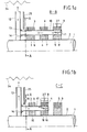
- slip rings 3, 4 and 5 are fastened on a shaft 1 of an electrical machine, in the present case an asynchronous machine, with the interposition of insulation 2.
- the slip rings in the longitudinal section to be considered first have all axially extending through holes 6, 7 and 8 which are aligned with one another. Spiral grooves 9 in the surface of the slip rings 3, 4 and 5 extend into these through bores 6, 7 and 8 and cut them.
- An insulating tube 10 leads through the through bores and is closed on the outer end face of the slip ring 5. In the area of the passage of the insulating tube 10 through the slip ring 5, the insulating tube 10 has a radially outward opening 11.
- the interior of the insulating tube 10 is thus connected to the grooves 9 of the slip ring 5 and thus to the exterior.
- the slip ring 5 is assigned four insulating tubes 10 which are uniformly distributed over the circumference.
- the insulating tubes 10 open at their free end in a radial fan 12 which is fixed on the shaft 1, and are held there in flange-like approaches 13, for. B. pressed, glued, cemented or screwed. By pulling down the fan blades 14 of the radial fan 12 to below the lower edge of the insulating tube 10, pre-twist losses are eliminated.
- the cooling connection of the slip ring 4 is illustrated in the longitudinal section of FIG. 1b.
- the slip rings 3 and 4 are provided with axially extending, mutually aligned through bores 15 and 16 through which an insulating tube 17 is guided.
- the insulating tube 17 is closed on the end face of the slip ring 4 facing the slip ring 5 and has an opening 18 directed radially outwards in the region of the passage through the slip ring 4.
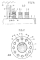
- the cooling connection of the Slip ring 3 according to FIG. 1c takes place in an analogous manner.
- Insulating tubes 20 are arranged in axial bores 21 of the slip ring 3.
- the insulating tubes 20 are closed on the end face of the slip ring 3 facing the slip ring 4. In the area of the passage through the slip ring 3, they have openings 22 directed radially outwards and open into the radial fan via flange-like projections 23.
- the slip ring 5 has four axial through-bores, the slip ring 4 has eight, four of which are used for the passage of the insulating tubes 10, the slip ring 3 has twelve through-bores, of which - as can be seen in FIG. 2 - eight bores for the passage of the insulating tubes 10 and 17 serve.
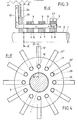
- FIGS. 1a, 1b, 1c and 2 illustrate a second embodiment of the subject matter of the invention, in which a cooling gas conveying device which has essentially the same effect takes the place of a radial fan.
- the slip rings 3, 4 and 5 are formed and connected to the insulating tubes 10, 17 and 20 in the same way as in the embodiment shown in FIGS. 1a, 1b, 1c and 2. Deviating from this, the ends 10 ', 17' and 20 'of the insulating tubes 10, 17 and 20 facing away from the slip rings are guided through a support ring 26 and bent radially outward behind the support ring. The ends of the insulating tubes protrude radially outward from the support ring 26 and are open there. Analogously to FIG.
- the partial cooling gas flows emerging from the bent ends of the insulating tubes are blown against a cooler 24 which surrounds the fan arrangement in a ring or reach the outside (in the case of open machines).
- a cooler 24 which surrounds the fan arrangement in a ring or reach the outside (in the case of open machines).
- the outflow space of the fan arrangement can be separated from the slip ring space by a fixed partition or partition 25 at the level of the supporting disk.
- cooling gas is drawn in through the insulating tubes by the fan.
- the (cold) cooling gas enters the grooves or grooves 9 in the surface of the slip rings and the radially outward openings 11, 18 and 22 in the insulating tubes 10, 17 and 20. Since cold cooling gas is also sucked out from under the brushes 27, in addition to the cooling effect on the brushes and the slip ring, brush abrasion is sucked off directly at the point of origin.
- the drawing omitted the (electrical) power supply or power dissipation for example. of the slip rings to illustrate.
- the electrical connection of the slip rings takes place on the side of the slip ring arrangement facing away from the fan, e.g. B. by one or more busbars or bolts per slip ring, the busbars associated with the slip rings 3 and 4 being passed through corresponding bores in the slip ring 4 and 5 isolated.
Landscapes
- Engineering & Computer Science (AREA)
- Power Engineering (AREA)
- Motor Or Generator Cooling System (AREA)
- Motor Or Generator Current Collectors (AREA)
Claims (9)
Priority Applications (1)
| Application Number | Priority Date | Filing Date | Title |
|---|---|---|---|
| AT81201079T ATE7988T1 (de) | 1980-11-13 | 1981-09-29 | Schleifringanordnung fuer elektrische maschinen. |
Applications Claiming Priority (2)
| Application Number | Priority Date | Filing Date | Title |
|---|---|---|---|
| CH8417/80 | 1980-11-13 | ||
| CH841780 | 1980-11-13 |
Publications (2)
| Publication Number | Publication Date |
|---|---|
| EP0052385A1 EP0052385A1 (fr) | 1982-05-26 |
| EP0052385B1 true EP0052385B1 (fr) | 1984-06-13 |
Family
ID=4340013
Family Applications (1)
| Application Number | Title | Priority Date | Filing Date |
|---|---|---|---|
| EP81201079A Expired EP0052385B1 (fr) | 1980-11-13 | 1981-09-29 | Dispositif de bague collectrice pour machines électriques |
Country Status (10)
| Country | Link |
|---|---|
| US (1) | US4410821A (fr) |
| EP (1) | EP0052385B1 (fr) |
| JP (1) | JPS57110051A (fr) |
| AR (1) | AR227564A1 (fr) |
| AT (1) | ATE7988T1 (fr) |
| BR (1) | BR8107314A (fr) |
| DE (1) | DE3164200D1 (fr) |
| ES (1) | ES8302959A1 (fr) |
| NO (1) | NO813766L (fr) |
| ZA (1) | ZA817789B (fr) |
Families Citing this family (27)
| Publication number | Priority date | Publication date | Assignee | Title |
|---|---|---|---|---|
| FR2559479B1 (fr) * | 1984-02-14 | 1986-07-18 | Atochem | Synthese d'acides perfluoroalcane-carboxyliques |
| FI96463C (fi) * | 1994-11-03 | 1996-06-25 | Abb Industry Oy | Järjestely sähkövirran, nestemäisen väliaineen ja kaasumaisen väliaineen siirtämiseksi asemaltaan kiinteän osan ja sen suhteen kiertyvän osan välillä |
| US5625244A (en) * | 1995-09-25 | 1997-04-29 | General Motors Corporation | Fan and slip ring assembly |
| BR0011512A (pt) * | 1999-05-10 | 2002-04-16 | Voith Siemens Hydro Power | Máquina elétrica |
| CA2412303C (fr) * | 2002-11-21 | 2010-05-04 | General Electric Canada Inc. | Nettoyage et refroidissement de collecteur de courant electrique pour machines tournantes a haute tension |
| DE102006050154A1 (de) * | 2006-10-21 | 2008-04-30 | Vem Sachsenwerk Gmbh | Kühlungsanordnung für Schleifringe bei rotierenden elektrischen Maschinen |
| DE102006058911B4 (de) * | 2006-12-13 | 2008-10-30 | Siemens Ag | Schleifringanordnung |
| US7750493B2 (en) * | 2007-08-14 | 2010-07-06 | General Electric Company | Wind turbine assemblies and slip ring assemblies for wind blade pitch control motors |
| JP5391657B2 (ja) * | 2008-11-14 | 2014-01-15 | 株式会社豊田中央研究所 | 回転電機用ブラシ摺接機構 |
| DE102009048265A1 (de) | 2009-10-05 | 2011-04-07 | Alstom Technology Ltd. | Schleifringanordnung für eine rotierende elektrische Maschine |
| EP2465185B1 (fr) | 2009-08-13 | 2013-12-25 | ALSTOM Renewable Technologies | Ensemble de bagues collectrices pour une machine électrique rotative |
| EP2317630A1 (fr) * | 2009-11-03 | 2011-05-04 | Alstom Technology Ltd | Système de refroidissement des traversées d'une génératrice électrique et méthode correspondante |
| US8558429B2 (en) | 2011-01-05 | 2013-10-15 | General Electric Company | Systems, methods, and apparatus for lifting brushes of an induction motor |
| US8674581B2 (en) | 2011-01-05 | 2014-03-18 | General Electric Company | Systems, methods, and apparatus for shorting slip rings of an induction motor |
| CN103081310B (zh) * | 2011-02-17 | 2015-08-12 | 三菱电机株式会社 | 集电环装置以及使用该集电环装置的旋转电机 |
| DE102011105759A1 (de) * | 2011-06-24 | 2012-12-27 | Kolektor Group D.O.O. | Dynamoelektrische Maschine |
| JP5862542B2 (ja) * | 2012-10-30 | 2016-02-16 | トヨタ自動車株式会社 | スリップリング装置 |
| JP5916223B2 (ja) * | 2012-12-05 | 2016-05-11 | トヨタ自動車株式会社 | スリップリング装置の冷却構造 |
| US9214777B2 (en) * | 2014-03-24 | 2015-12-15 | Goodrich Corporation | Landing gear electrical swivel |
| EP2924817B1 (fr) * | 2014-03-27 | 2018-08-29 | Schleifring GmbH | Bague collectrice avec refroidissement actif |
| EP3322047A1 (fr) | 2016-11-15 | 2018-05-16 | Siemens Aktiengesellschaft | Unité de bague collectrice comprenant un segment d'isolant de ventilateur |
| EP3599677A1 (fr) * | 2018-07-27 | 2020-01-29 | Siemens Aktiengesellschaft | Bague collectrice, unité de bague collectrice, machine électrique et éolienne |
| EP3599678A1 (fr) * | 2018-07-27 | 2020-01-29 | Siemens Aktiengesellschaft | Bague collectrice, unité de bague collectrice, machine électrique et éolienne |
| ES2866408T3 (es) * | 2018-08-21 | 2021-10-19 | Flender Gmbh | Puente de anillo colector, unidad de anillo colector, máquina eléctrica y turbina eólica |
| EP3618204A1 (fr) * | 2018-08-27 | 2020-03-04 | Siemens Aktiengesellschaft | Corps de bague collectrices |
| DE112022007666T5 (de) * | 2022-08-16 | 2025-05-28 | Cebes A.S. | Schleifringanordnung für einen doppelt gespeisten induktionsgenerator |
| EP4557588A1 (fr) * | 2023-11-17 | 2025-05-21 | Flender GmbH | Bague collectrice avec moyeu de ventilateur isolé |
Family Cites Families (15)
| Publication number | Priority date | Publication date | Assignee | Title |
|---|---|---|---|---|
| DE504351C (de) * | 1927-05-29 | 1930-08-02 | Siemens Schuckertwerke Akt Ges | Anordnung zur Entfernung des Buerstenstaubes von den ungekapselten Schleifringen elektrischer Maschinen |
| AT135609B (de) * | 1932-02-17 | 1933-11-25 | Bbc Brown Boveri & Cie | Drehstrommaschine mit Ventilator, Kommutator und Schleifringen. |
| DE854970C (de) * | 1944-10-22 | 1952-11-10 | Siemens Ag | Lueftungsanordnung fuer den Kommutator elektrischer Maschinen |
| DE1266866B (de) * | 1962-06-09 | 1968-04-25 | Siemens Ag | Gasgekuehlter Schleifring fuer elektrische Maschinen |
| BE633774A (fr) * | 1963-06-19 | 1963-12-19 | Acec | Collecteur à bagues |
| JPS5526669B1 (fr) * | 1970-10-05 | 1980-07-15 | ||
| CH530726A (de) * | 1970-10-27 | 1972-11-15 | Bbc Brown Boveri & Cie | Einrichtung an einer elektrischen Maschine zur Kühlung von deren Stromzu- oder Stromabnahmevorrichtung |
| CH524267A (de) * | 1970-11-20 | 1972-06-15 | Bbc Brown Boveri & Cie | Aus Schleifring und Bürsten bestehende Stromübertragungsvorrichtung an Generatoren |
| JPS49105104A (fr) * | 1973-02-12 | 1974-10-04 | ||
| US4137474A (en) * | 1974-06-04 | 1979-01-30 | Kraftwerk Union Aktiengesellschaft | Gas-cooled slip ring for electrical machines |
| JPS5120401U (fr) * | 1974-07-31 | 1976-02-14 | ||
| JPS52144702A (en) * | 1976-05-28 | 1977-12-02 | Hitachi Ltd | Current collector for rotary machine |
| DE2750410A1 (de) * | 1977-10-19 | 1979-04-26 | Bbc Brown Boveri & Cie | Schleifringanordnung |
| JPS554685A (en) * | 1978-06-27 | 1980-01-14 | Nec Corp | Microprogram control unit |
| JPS55157956A (en) * | 1979-05-29 | 1980-12-09 | Hitachi Ltd | Collector cooler for rotary electric machine |
-
1981
- 1981-09-29 AT AT81201079T patent/ATE7988T1/de not_active IP Right Cessation
- 1981-09-29 DE DE8181201079T patent/DE3164200D1/de not_active Expired
- 1981-09-29 EP EP81201079A patent/EP0052385B1/fr not_active Expired
- 1981-11-06 NO NO813766A patent/NO813766L/no unknown
- 1981-11-11 ES ES507032A patent/ES8302959A1/es not_active Expired
- 1981-11-11 AR AR287411A patent/AR227564A1/es active
- 1981-11-11 ZA ZA817789A patent/ZA817789B/xx unknown
- 1981-11-11 BR BR8107314A patent/BR8107314A/pt unknown
- 1981-11-12 US US06/320,438 patent/US4410821A/en not_active Expired - Fee Related
- 1981-11-13 JP JP56181246A patent/JPS57110051A/ja active Pending
Also Published As
| Publication number | Publication date |
|---|---|
| JPS57110051A (en) | 1982-07-08 |
| DE3164200D1 (en) | 1984-07-19 |
| NO813766L (no) | 1982-05-14 |
| ES507032A0 (es) | 1982-12-01 |
| AR227564A1 (es) | 1982-11-15 |
| ATE7988T1 (de) | 1984-06-15 |
| ES8302959A1 (es) | 1982-12-01 |
| BR8107314A (pt) | 1982-08-03 |
| US4410821A (en) | 1983-10-18 |
| ZA817789B (en) | 1982-10-27 |
| EP0052385A1 (fr) | 1982-05-26 |
Similar Documents
| Publication | Publication Date | Title |
|---|---|---|
| EP0052385B1 (fr) | Dispositif de bague collectrice pour machines électriques | |
| DE69411498T2 (de) | Staubsaugergerät | |
| WO2004093292A2 (fr) | Machine electrique a empilages de toles et bobines de stator et de rotor refroidis | |
| DE2714299C2 (de) | Zusatzkühlung für eine Offenendspinnvorrichtung mit einem Spinnrotor | |
| DE102010001437B4 (de) | Dynamoelektrische Maschine mit einem Schleifringläufer und geschlossener Schleifringanordnung | |
| DE1463874B2 (de) | Kuehlanordnung fuer die wickelkoepfe eines gasgekuehlten rotors einer elektrischen maschine, insbesondere eines wasserstoffgekuehlten generators | |
| DE102019217510A1 (de) | Rotor, Elektromaschine und Kraftfahrzeug | |
| DE102019113091A1 (de) | Führungsvorrichtung für ein Wicklungsköpfe einer elektrische Maschine umfließendes Kühlfluid und elektrische Maschine | |
| DE2422962A1 (de) | Schleifring- und buerstenanordnung | |
| EP0589187B1 (fr) | Machine électrique entièrement fermeé, refroidie en surface par liquide | |
| DE2743826B2 (de) | Elektromotor, der mit seinem abtriebsseitigen Ende an der Wand einer Arbeitsmaschine, insbesondere Geschirrspülmaschine, befestigt ist | |
| EP0585644B1 (fr) | Machine électrique entièrement fermée, refroidie en surface par liquide | |
| EP2982024B1 (fr) | Boîtier pour une machine électrique | |
| DE102006058911B4 (de) | Schleifringanordnung | |
| DE19608286B4 (de) | Belüftungssystem für den Ringmotor einer Rohrmühle | |
| DE102019113159A1 (de) | Elektrische Maschine mit Ölkühlung | |
| DE102021211920A1 (de) | Stator für eine elektrische Maschine | |
| EP0345667B1 (fr) | Dispositif de refroidissement pour une extrémité d'une machine textile en particulier une machine à filer | |
| WO2008107402A2 (fr) | Machine électrique rotative | |
| DE949756C (de) | Gekapselte elektrische Maschine mit im Kreislauf gefuehrtem Innenkuehlluftstrom | |
| EP1992054B1 (fr) | Dispositif pour enrouler un cable electrique | |
| DE1134189B (de) | Einrichtung zur Abfuehrung der in Elektromotoren entstehenden Verlustwaerme bei Seilwinden | |
| EP3211761B1 (fr) | Moteur électrique refroidi par air | |
| DE8525254U1 (de) | Brandgasventilator | |
| DE202006016164U1 (de) | Anordnung zur Kühlmediumführung zur Schleifringraumbelüftung für Schleifringläufermaschinen |
Legal Events
| Date | Code | Title | Description |
|---|---|---|---|
| PUAI | Public reference made under article 153(3) epc to a published international application that has entered the european phase |
Free format text: ORIGINAL CODE: 0009012 |
|
| AK | Designated contracting states |
Designated state(s): AT CH DE FR GB IT SE |
|
| 17P | Request for examination filed |
Effective date: 19820927 |
|
| GRAA | (expected) grant |
Free format text: ORIGINAL CODE: 0009210 |
|
| AK | Designated contracting states |
Designated state(s): AT CH DE FR GB IT LI SE |
|
| PG25 | Lapsed in a contracting state [announced via postgrant information from national office to epo] |
Ref country code: SE Effective date: 19840613 Ref country code: IT Free format text: LAPSE BECAUSE OF FAILURE TO SUBMIT A TRANSLATION OF THE DESCRIPTION OR TO PAY THE FEE WITHIN THE PRESCRIBED TIME-LIMIT;WARNING: LAPSES OF ITALIAN PATENTS WITH EFFECTIVE DATE BEFORE 2007 MAY HAVE OCCURRED AT ANY TIME BEFORE 2007. THE CORRECT EFFECTIVE DATE MAY BE DIFFERENT FROM THE ONE RECORDED. Effective date: 19840613 Ref country code: FR Free format text: THE PATENT HAS BEEN ANNULLED BY A DECISION OF A NATIONAL AUTHORITY Effective date: 19840613 |
|
| REF | Corresponds to: |
Ref document number: 7988 Country of ref document: AT Date of ref document: 19840615 Kind code of ref document: T |
|
| REF | Corresponds to: |
Ref document number: 3164200 Country of ref document: DE Date of ref document: 19840719 |
|
| PGFP | Annual fee paid to national office [announced via postgrant information from national office to epo] |
Ref country code: DE Payment date: 19840908 Year of fee payment: 4 |
|
| PGFP | Annual fee paid to national office [announced via postgrant information from national office to epo] |
Ref country code: CH Payment date: 19841023 Year of fee payment: 4 |
|
| PLBI | Opposition filed |
Free format text: ORIGINAL CODE: 0009260 |
|
| 26 | Opposition filed |
Opponent name: KRAFTWERK UNION AKTIENGESELLSCHAFT Effective date: 19850313 |
|
| EN | Fr: translation not filed | ||
| PGFP | Annual fee paid to national office [announced via postgrant information from national office to epo] |
Ref country code: AT Payment date: 19860909 Year of fee payment: 6 |
|
| PG25 | Lapsed in a contracting state [announced via postgrant information from national office to epo] |
Ref country code: LI Effective date: 19860930 Ref country code: CH Effective date: 19860930 |
|
| PLBN | Opposition rejected |
Free format text: ORIGINAL CODE: 0009273 |
|
| PLAE | Information related to rejection of opposition modified |
Free format text: ORIGINAL CODE: 0009299REJO |
|
| STAA | Information on the status of an ep patent application or granted ep patent |
Free format text: STATUS: OPPOSITION REJECTED |
|
| 27O | Opposition rejected |
Effective date: 19861121 |
|
| R27O | Information related to the rejection of opposition modified: opposition rejected |
Free format text: 860919 |
|
| REG | Reference to a national code |
Ref country code: CH Ref legal event code: PL |
|
| PG25 | Lapsed in a contracting state [announced via postgrant information from national office to epo] |
Ref country code: GB Effective date: 19880929 Ref country code: AT Effective date: 19880929 |
|
| GBPC | Gb: european patent ceased through non-payment of renewal fee | ||
| PG25 | Lapsed in a contracting state [announced via postgrant information from national office to epo] |
Ref country code: DE Effective date: 19890601 |
|
| ITTA | It: last paid annual fee | ||
| PLAB | Opposition data, opponent's data or that of the opponent's representative modified |
Free format text: ORIGINAL CODE: 0009299OPPO |