EP0052528A1 - Rolle für Wagen, insbesondere Selbstbedienungswagen, zum Blockiern des Wagens auf einer Rolltreppe und Wagen mit einer derartigen Rolle - Google Patents
Rolle für Wagen, insbesondere Selbstbedienungswagen, zum Blockiern des Wagens auf einer Rolltreppe und Wagen mit einer derartigen Rolle Download PDFInfo
- Publication number
- EP0052528A1 EP0052528A1 EP81401411A EP81401411A EP0052528A1 EP 0052528 A1 EP0052528 A1 EP 0052528A1 EP 81401411 A EP81401411 A EP 81401411A EP 81401411 A EP81401411 A EP 81401411A EP 0052528 A1 EP0052528 A1 EP 0052528A1
- Authority
- EP
- European Patent Office
- Prior art keywords
- wheel
- shoe
- fork
- carriage
- trolley
- Prior art date
- Legal status (The legal status is an assumption and is not a legal conclusion. Google has not performed a legal analysis and makes no representation as to the accuracy of the status listed.)
- Granted
Links
Images



Classifications
-
- B—PERFORMING OPERATIONS; TRANSPORTING
- B60—VEHICLES IN GENERAL
- B60B—VEHICLE WHEELS; CASTORS; AXLES FOR WHEELS OR CASTORS; INCREASING WHEEL ADHESION
- B60B33/00—Castors in general ; Anti-clogging castors
- B60B33/02—Castors in general ; Anti-clogging castors with disengageable swivel action, i.e. comprising a swivel locking mechanism
- B60B33/021—Castors in general ; Anti-clogging castors with disengageable swivel action, i.e. comprising a swivel locking mechanism combined with braking of castor wheel
-
- B—PERFORMING OPERATIONS; TRANSPORTING
- B62—LAND VEHICLES FOR TRAVELLING OTHERWISE THAN ON RAILS
- B62B—HAND-PROPELLED VEHICLES, e.g. HAND CARTS OR PERAMBULATORS; SLEDGES
- B62B5/00—Accessories or details specially adapted for hand carts
- B62B5/02—Accessories or details specially adapted for hand carts providing for travelling up or down a flight of stairs
- B62B5/021—Accessories or details specially adapted for hand carts providing for travelling up or down a flight of stairs specially adapted for escalators
-
- B—PERFORMING OPERATIONS; TRANSPORTING
- B60—VEHICLES IN GENERAL
- B60B—VEHICLE WHEELS; CASTORS; AXLES FOR WHEELS OR CASTORS; INCREASING WHEEL ADHESION
- B60B2200/00—Type of product being used or applied
- B60B2200/40—Articles of daily use
- B60B2200/43—Carts
- B60B2200/432—Shopping carts
Definitions
- the present invention relates to a wheel for trolleys, in particular self-service shops in which the floors are connected by escalators or ribbed conveyor belts.
- this wheel could be used for transporting trolleys of different types, on conveyors and / or ribbed escalators.
- French Patent 1,362,308 thus describes a carriage, the wheels of which are provided with lateral pads placed in the axis of the wheel, slightly above the bearing surface of the wheel on the ground, the wheel having projecting bands. of rolling.
- the projecting bands engage in the grooves of the treadmill, and the side runners automatically act as brakes by coming to bear on the ribs of the treadmill.
- German patent 2,656,322 also describes wheels fitted with a brake acting in a similar manner, but which is placed between the two treads of the wheel.
- the invention therefore aims to remedy these shortcomings by providing a wheel equipped with a carriage blocking pad in an escalator, designed so as not to rub on the entry or exit comb of the staircase .
- the wheel covered by the invention comprises a shoe located in the plane of the wheel, adapted to block the latter when the carriage is engaged in a rolling staircase.
- the tangent to the bearing surface of the skate on the staircase and to the lower part of the circumference of the wheel is inclined to the horizontal by an angle of between approximately 20 and 37 degrees, and the bearing surface of the pad is located at a height between about half the radius of the wheel and the axis thereof.
- the blocking shoe always remains sufficiently above the entry or exit comb of the staircase so as not to risk rubbing against it.
- the bearing surface of the blocking pad is situated practically at the height of the center of the wheel, which constitutes in practice the maximum acceptable height so that this skate can actually come into action taking into account the usual inclinations of escalators.
- the skate is integral with a fork whose arms extend on each side of the wheel and are fixed to a yoke in which the wheel is mounted.
- the fork being made in one piece, integral on the one hand with the axis of the wheel, and on the other hand with the upper part of the fork, this gives a particularly robust construction, which allows the blocking shoe to withstand significant forces during the ascent or descent of an escalator, without its support fork being likely to loosen.
- This also constitutes an advantage compared to the known embodiment mentioned above, in which the blocking stirrup is simply fixed to the lower part of the yoke of the wheel at the axis of the latter, by means of bolts that are likely to loosen gradually.
- the wheel according to the invention can be equipped with a front shoe and a rear shoe, serving alternately during the descent and during the ascent of an escalator, as well as in a known manner, with a lateral shoe placed in the axis of the wheel, and which acts when the wheel is on a ribbed conveyor or on the ribbed steps at the start of an escalator.
- a front shoe and a rear shoe serving alternately during the descent and during the ascent of an escalator, as well as in a known manner, with a lateral shoe placed in the axis of the wheel, and which acts when the wheel is on a ribbed conveyor or on the ribbed steps at the start of an escalator.
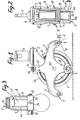
- the wheel shown in Figures 1 and 2 is intended to equip a trolley not shown, preferably but not exclusively a trolley for self-service stores in which the different floors are connected by escalators or ribbed conveyors.
- the wheel 1. is of the type comprising two peripheral treads 1a projecting from a central strip 1b, and by which the wheel 1 is supported on the ground.
- the projecting strips 1a are dimensioned so as to be able to be introduced into the grooves separating the ribs of the conveyor belts or the steps of the escalators.
- the wheel 1 is mounted in a yoke 2 on which is fixed in a known manner a lug 3 secured to the lower frame (not shown) of the carriage.
- the wheel is provided with a lateral braking pad 4, intended to brake or block the carriage when the latter engages on a ribbed conveyor belt or at the start of an escalator with ribbed steps, the projecting bands 1a engaging as indicated above between the ribs thereof.
- the wheel is also provided with two similar pads 5 placed in the general plane of the wheel 1, and adapted to block the latter when the trolley is engaged in an escalator.
- the tangent T to the bearing surface of the shoe 5 on the staircase and to the lower part of the circumference of the wheel 1, that is to say more precisely in the example described the part bottom of the central strip 1b, is inclined to the horizontal H by an angle ⁇ between about 20 and 37 degrees (26 degrees in Figure 1).
- the bearing surface of the shoe 5 is located at a height between approximately half the radius of the wheel 1, and more precisely of the treads 1a, and the height of the axis X-X thereof.
- the extreme positions of the blocking pads 5 are shown in dashed lines in FIG. 1, the right pad being in its maximum upper position, and the left pad in its lower limit position.
- Each shoe 5 is constituted, in the example described, by a knurled cylindrical spacer 6, the ends of which are crimped to the parallel arms 7 of a fork 8 which extend on each side of the wheel 1 and are connected by a part transverse upper 9 above the wheel 1.
- This intermediate part 9 comes cover part 2a of the yoke 2, on which it is kept applied strongly by bolts 11 passing through the fork 8 and the lower parts of the yoke 2, in the axis XX of the wheel 1.
- the stirrup or fork 8 thus comprises, for each blocking pad 5, a pair of arms 7 extending approximately radially with respect to the wheel 1, and which meet above the axis of the latter being extended by vertical arms 12 connected by the upper part 9.
- This assembly is completed by a lower radial arm 13 carrying at its lower end the lateral braking shoe 4.
- the elements 7, 12, 13 and 9 are made in one piece and thus constitute a piece coming from foundry or thick sheet metal stamped extremely solid.
- the assembly formed by the yoke 2 and the arms 7, 12, 13 with their shoes 4, 5 pivots about the axis XX, so that one of the shoes 5 comes into contact with the surface of the stairs while the other gets up; the shoe in contact with the staircase then ensures the blocking of the carriage as will be explained in more detail below.
- the angular position of the spacers or blocking pads 6, identified by the inclination 0 (of the tangent T on the horizontal, can be adjusted after proper positioning of the branches 12 of the stirrup 8 on the yoke 2, by tightening the bolts 11.
- means are provided for adjusting the angular position of the skids 5 as a function of the inclination of the staircase.
- These means consist of a bolt or stud 14, passing through the upper part 9 of the stirrup 8, as well as an oblong hole 15 formed in the transverse part. 2a of the yoke 2, and elongated in the vertical median plane of the wheel 1, as can be clearly seen in FIG. 3.
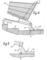
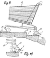
- Figures 4 to 10 show the successive phases of the rise of a carriage 17 on an escalator 18 whose steps have grooves 19 and move under an entry comb 21.
- the carriage 17 is equipped in this example rear wheels. 22 each provided with a single rear blocking block 5.
- Each wheel 22 is also provided with a lateral brake pad 4.
- the carriage 17 is mounted on the escalator 18 in the following manner.
- the wheel 22 lifts above the step 18a, and the rear runners 5 support most of the weight of the carriage.
- the pads can thus undergo without disadvantage high stresses during the ascent of the carriage, thanks to the very solid construction formed by the stirrup 8 locked at the axis of the wheel 1 and on the yoke 2.
- FIGS. 11 to 17 illustrate the successive phases of the descent of a carriage 26 on the staircase 18, this carriage being provided with rear wheels 27 identical to the wheel of FIGS. 1 and 2, that is to say each with two front and rear brakes 5.
- Figures 13 to 15 show the position of the carriage 26 and the brakes 4, 5 during the descent of the staircase 18: this having a slope of 35 degrees ( Figures 13 and 14), the assembly of the wheel 27 is raised above step 18a, and the front brake 5 is supported on it, blocking the carriage 26.
- the staircase 18 has a slope of only 30 degrees, and the treads of the wheel 1 are approximately tangent to the ribs of the step 18a.
- the front wheels 23 arrive in front of the outlet comb 21 while the carriage progressively lowers to the horizontal, the front brake 5 being raised above the step 18a and the side brake 4 coming back into contact with it.
- the lateral brake 4 blocks the carriage 27 while the wheels 23 advance on the comb 21, allowing the carriage to exit in the same way as it leaves at the top of the escalator 18.
- the wheel 22, provided with a single rear brake 5 makes it possible to block the carriage only during the ascent of the staircase, while the wheel 27 provided with two brakes 5 front and rear, makes it possible to block the carriage both during the ascent and during the descent of the staircase 18.
- the internal lateral brake 4 fixed in the axis of the wheel 1 serves as a blocking as the carriage remains horizontal on the steps of the escalator 18 as the carriage inclines, the spacer 5, before or rear, depending on whether the cart goes down or up, takes over and acts fully in the tilted position of the cart on the stairs.
- the invention is not limited to the embodiments described and may include alternative embodiments.
- the spacer 6 could be replaced by a lining similar to the lining constituting the brake 4. But this lining constituting a wearing part would be substantially less advantageous than the knurled spacer 6.
- the wheel could also be devoid of projecting treads and side brake shoe.
- the vertical distance between the bearing surface of the locking spacer 6 and the axis XX of the wheel can be 12 mm, 'and the height of the combs of the escalator 30 mm, and their inclination to the horizontal by 25 degrees.
Landscapes
- Engineering & Computer Science (AREA)
- Mechanical Engineering (AREA)
- Chemical & Material Sciences (AREA)
- Combustion & Propulsion (AREA)
- Transportation (AREA)
- Handcart (AREA)
- Escalators And Moving Walkways (AREA)
Applications Claiming Priority (2)
| Application Number | Priority Date | Filing Date | Title |
|---|---|---|---|
| FR8024216A FR2494193A1 (fr) | 1980-11-14 | 1980-11-14 | Roue pour chariots, notamment de magasins a libre-service, permettant le blocage du chariot dans des escaliers roulants et chariot muni de cette roue |
| FR8024216 | 1980-11-14 |
Publications (2)
| Publication Number | Publication Date |
|---|---|
| EP0052528A1 true EP0052528A1 (de) | 1982-05-26 |
| EP0052528B1 EP0052528B1 (de) | 1984-12-05 |
Family
ID=9247968
Family Applications (1)
| Application Number | Title | Priority Date | Filing Date |
|---|---|---|---|
| EP19810401411 Expired EP0052528B1 (de) | 1980-11-14 | 1981-09-11 | Rolle für Wagen, insbesondere Selbstbedienungswagen, zum Blockiern des Wagens auf einer Rolltreppe und Wagen mit einer derartigen Rolle |
Country Status (3)
| Country | Link |
|---|---|
| EP (1) | EP0052528B1 (de) |
| DE (2) | DE3167632D1 (de) |
| FR (1) | FR2494193A1 (de) |
Cited By (2)
| Publication number | Priority date | Publication date | Assignee | Title |
|---|---|---|---|---|
| FR2714007A1 (fr) * | 1993-12-21 | 1995-06-23 | Caddie Atel Reunis | Chariot à bagages pouvant être placé sur un escalier mécanique. |
| US9950564B2 (en) * | 2010-04-05 | 2018-04-24 | Douglas G. Willis | Articulating carriage |
Families Citing this family (6)
| Publication number | Priority date | Publication date | Assignee | Title |
|---|---|---|---|---|
| US4989920A (en) * | 1983-05-27 | 1991-02-05 | University Of Virginia Alumni Patents Found. | Self-damping caster wheel |
| DE19542310A1 (de) * | 1995-11-14 | 1997-05-15 | Wanzl Metallwarenfabrik Kg | Einrichtung zum Befördern von Gegenständen |
| DE19718060A1 (de) * | 1997-04-29 | 1998-11-05 | Wanzl Entwicklung Gmbh | Von Hand bewegbarer Transportwagen |
| US6126176A (en) * | 1997-09-08 | 2000-10-03 | Exedy Corporation | Fall suppressing device for a vehicle configured to ride on descending and ascending escalators |
| DE29919764U1 (de) * | 1999-11-10 | 2000-01-05 | Wanzl Metallwarenfabrik Gmbh, 89340 Leipheim | Gepäcktransportwagen |
| CN110902544B (zh) * | 2019-12-11 | 2024-07-26 | 广州广日电梯工业有限公司 | 一种购物车专用扶梯系统 |
Citations (1)
| Publication number | Priority date | Publication date | Assignee | Title |
|---|---|---|---|---|
| FR2099196A5 (de) * | 1970-06-20 | 1972-03-10 | Schulte & Co Kugelfab |
-
1980
- 1980-11-14 FR FR8024216A patent/FR2494193A1/fr active Granted
-
1981
- 1981-09-11 DE DE8181401411T patent/DE3167632D1/de not_active Expired
- 1981-09-11 EP EP19810401411 patent/EP0052528B1/de not_active Expired
- 1981-11-12 DE DE19818133435 patent/DE8133435U1/de not_active Expired
Patent Citations (1)
| Publication number | Priority date | Publication date | Assignee | Title |
|---|---|---|---|---|
| FR2099196A5 (de) * | 1970-06-20 | 1972-03-10 | Schulte & Co Kugelfab |
Cited By (2)
| Publication number | Priority date | Publication date | Assignee | Title |
|---|---|---|---|---|
| FR2714007A1 (fr) * | 1993-12-21 | 1995-06-23 | Caddie Atel Reunis | Chariot à bagages pouvant être placé sur un escalier mécanique. |
| US9950564B2 (en) * | 2010-04-05 | 2018-04-24 | Douglas G. Willis | Articulating carriage |
Also Published As
| Publication number | Publication date |
|---|---|
| DE3167632D1 (en) | 1985-01-17 |
| FR2494193B1 (de) | 1985-02-22 |
| DE8133435U1 (de) | 1982-04-29 |
| EP0052528B1 (de) | 1984-12-05 |
| FR2494193A1 (fr) | 1982-05-21 |
Similar Documents
| Publication | Publication Date | Title |
|---|---|---|
| EP0340260B1 (de) | Rollschuh mit mindestens zwei ausgerichteten rädern entlang einer mittelfläche | |
| EP0795348B1 (de) | Einspuriger Rollschuh mit Bremse | |
| CA2797678C (fr) | Siege de remontee mecanique a dispositif de transport de bicyclette | |
| FR2599700A1 (fr) | Chariot de transport de fauteuil roulant dans des escaliers | |
| EP0760295B1 (de) | Wagen mit einem auf Lenkrollen montierten Gestell und Lenkrollen für solchen Wagen | |
| FR2538245A1 (fr) | Dispositif de transport de secours pour malades | |
| EP0052528B1 (de) | Rolle für Wagen, insbesondere Selbstbedienungswagen, zum Blockiern des Wagens auf einer Rolltreppe und Wagen mit einer derartigen Rolle | |
| CH676086A5 (de) | ||
| FR2635296A1 (fr) | Roue pour chariot ou similaire comportant un dispositif de blocage sur un plan incline | |
| EP1156859A1 (de) | Einspurrollschuh mit bremsanordnung | |
| EP0572297B1 (de) | Haltervorrichtung für Fahrrollen und Koffer mit einer solchen Vorrichtung | |
| FR2481606A1 (fr) | Vehicule permettant de descendre une piste en forme de gouttiere | |
| WO2000064724A1 (fr) | Chariot de transport de skis | |
| CH628819A5 (fr) | Patin a roulettes et accessoire pour le patin a roulettes. | |
| EP0809600B1 (de) | Lastaufnahme-fahrzeug | |
| WO1993024029A1 (fr) | Bagage souple ou rigide a roulettes comportant une poignee | |
| FR2768113A1 (fr) | Mecanisme de freinage pour chariot | |
| FR2620995A1 (fr) | Chariot pour le transport de bagages, destine a pouvoir etre place sur un escalier mecanique | |
| FR2556228A1 (fr) | Patins a roulettes, dont les roues ont une inclinaison variable par rapport au sol | |
| FR2462378A1 (fr) | Installation pour le transport de chariot a bagages, etc. sur des escaliers roulants | |
| FR2714007A1 (fr) | Chariot à bagages pouvant être placé sur un escalier mécanique. | |
| FR2511644A1 (fr) | Chariot a bagages manoeuvrable a la main, emboitable avec des chariots similaires | |
| CA1316190C (fr) | Patin a roulettes comportant au moins deux roulettes alignees le long d'un plan median | |
| EP1029710A1 (de) | Wagen mit einem auf Lenkrollen montierten Gestell und Lenkrollen für solchen Wagen | |
| FR2854815A1 (fr) | Dispositif destine a faciliter le transport de skis |
Legal Events
| Date | Code | Title | Description |
|---|---|---|---|
| PUAI | Public reference made under article 153(3) epc to a published international application that has entered the european phase |
Free format text: ORIGINAL CODE: 0009012 |
|
| AK | Designated contracting states |
Designated state(s): DE GB |
|
| 17P | Request for examination filed |
Effective date: 19820408 |
|
| GRAA | (expected) grant |
Free format text: ORIGINAL CODE: 0009210 |
|
| AK | Designated contracting states |
Designated state(s): DE GB |
|
| REF | Corresponds to: |
Ref document number: 3167632 Country of ref document: DE Date of ref document: 19850117 |
|
| PLBE | No opposition filed within time limit |
Free format text: ORIGINAL CODE: 0009261 |
|
| STAA | Information on the status of an ep patent application or granted ep patent |
Free format text: STATUS: NO OPPOSITION FILED WITHIN TIME LIMIT |
|
| 26N | No opposition filed | ||
| PGFP | Annual fee paid to national office [announced via postgrant information from national office to epo] |
Ref country code: GB Payment date: 19910930 Year of fee payment: 11 |
|
| PGFP | Annual fee paid to national office [announced via postgrant information from national office to epo] |
Ref country code: DE Payment date: 19911001 Year of fee payment: 11 |
|
| PG25 | Lapsed in a contracting state [announced via postgrant information from national office to epo] |
Ref country code: GB Effective date: 19920911 |
|
| GBPC | Gb: european patent ceased through non-payment of renewal fee |
Effective date: 19920911 |
|
| PG25 | Lapsed in a contracting state [announced via postgrant information from national office to epo] |
Ref country code: DE Effective date: 19930602 |