EP0052773A2 - Dispositif de distribution - Google Patents
Dispositif de distribution Download PDFInfo
- Publication number
- EP0052773A2 EP0052773A2 EP81108787A EP81108787A EP0052773A2 EP 0052773 A2 EP0052773 A2 EP 0052773A2 EP 81108787 A EP81108787 A EP 81108787A EP 81108787 A EP81108787 A EP 81108787A EP 0052773 A2 EP0052773 A2 EP 0052773A2
- Authority
- EP
- European Patent Office
- Prior art keywords
- evaporator
- evaporator tubes
- distance
- distributor housing
- refrigerant
- Prior art date
- Legal status (The legal status is an assumption and is not a legal conclusion. Google has not performed a legal analysis and makes no representation as to the accuracy of the status listed.)
- Granted
Links
- 239000003507 refrigerant Substances 0.000 claims abstract description 23
- 239000007788 liquid Substances 0.000 claims abstract description 15
- 238000002347 injection Methods 0.000 claims abstract description 14
- 239000007924 injection Substances 0.000 claims abstract description 14
- 239000000203 mixture Substances 0.000 claims abstract description 11
- 239000007789 gas Substances 0.000 description 3
- 125000006850 spacer group Chemical group 0.000 description 3
- 239000007792 gaseous phase Substances 0.000 description 2
- 239000007791 liquid phase Substances 0.000 description 2
- 238000005452 bending Methods 0.000 description 1
- 230000001934 delay Effects 0.000 description 1
- 230000000694 effects Effects 0.000 description 1
- 238000013021 overheating Methods 0.000 description 1
- 230000000630 rising effect Effects 0.000 description 1
- 239000000243 solution Substances 0.000 description 1
- 238000011144 upstream manufacturing Methods 0.000 description 1
- XLYOFNOQVPJJNP-UHFFFAOYSA-N water Substances O XLYOFNOQVPJJNP-UHFFFAOYSA-N 0.000 description 1
Images

Classifications
-
- F—MECHANICAL ENGINEERING; LIGHTING; HEATING; WEAPONS; BLASTING
- F28—HEAT EXCHANGE IN GENERAL
- F28F—DETAILS OF HEAT-EXCHANGE AND HEAT-TRANSFER APPARATUS, OF GENERAL APPLICATION
- F28F9/00—Casings; Header boxes; Auxiliary supports for elements; Auxiliary members within casings
- F28F9/02—Header boxes; End plates
- F28F9/026—Header boxes; End plates with static flow control means, e.g. with means for uniformly distributing heat exchange media into conduits
- F28F9/027—Header boxes; End plates with static flow control means, e.g. with means for uniformly distributing heat exchange media into conduits in the form of distribution pipes
- F28F9/0275—Header boxes; End plates with static flow control means, e.g. with means for uniformly distributing heat exchange media into conduits in the form of distribution pipes with multiple branch pipes
-
- B—PERFORMING OPERATIONS; TRANSPORTING
- B01—PHYSICAL OR CHEMICAL PROCESSES OR APPARATUS IN GENERAL
- B01D—SEPARATION
- B01D1/00—Evaporating
- B01D1/30—Accessories for evaporators ; Constructional details thereof
-
- F—MECHANICAL ENGINEERING; LIGHTING; HEATING; WEAPONS; BLASTING
- F25—REFRIGERATION OR COOLING; COMBINED HEATING AND REFRIGERATION SYSTEMS; HEAT PUMP SYSTEMS; MANUFACTURE OR STORAGE OF ICE; LIQUEFACTION SOLIDIFICATION OF GASES
- F25B—REFRIGERATION MACHINES, PLANTS OR SYSTEMS; COMBINED HEATING AND REFRIGERATION SYSTEMS; HEAT PUMP SYSTEMS
- F25B39/00—Evaporators; Condensers
- F25B39/02—Evaporators
- F25B39/028—Evaporators having distributing means
-
- F—MECHANICAL ENGINEERING; LIGHTING; HEATING; WEAPONS; BLASTING
- F25—REFRIGERATION OR COOLING; COMBINED HEATING AND REFRIGERATION SYSTEMS; HEAT PUMP SYSTEMS; MANUFACTURE OR STORAGE OF ICE; LIQUEFACTION SOLIDIFICATION OF GASES
- F25B—REFRIGERATION MACHINES, PLANTS OR SYSTEMS; COMBINED HEATING AND REFRIGERATION SYSTEMS; HEAT PUMP SYSTEMS
- F25B41/00—Fluid-circulation arrangements
-
- F—MECHANICAL ENGINEERING; LIGHTING; HEATING; WEAPONS; BLASTING
- F25—REFRIGERATION OR COOLING; COMBINED HEATING AND REFRIGERATION SYSTEMS; HEAT PUMP SYSTEMS; MANUFACTURE OR STORAGE OF ICE; LIQUEFACTION SOLIDIFICATION OF GASES
- F25B—REFRIGERATION MACHINES, PLANTS OR SYSTEMS; COMBINED HEATING AND REFRIGERATION SYSTEMS; HEAT PUMP SYSTEMS
- F25B41/00—Fluid-circulation arrangements
- F25B41/40—Fluid line arrangements
- F25B41/42—Arrangements for diverging or converging flows, e.g. branch lines or junctions
-
- F—MECHANICAL ENGINEERING; LIGHTING; HEATING; WEAPONS; BLASTING
- F25—REFRIGERATION OR COOLING; COMBINED HEATING AND REFRIGERATION SYSTEMS; HEAT PUMP SYSTEMS; MANUFACTURE OR STORAGE OF ICE; LIQUEFACTION SOLIDIFICATION OF GASES
- F25B—REFRIGERATION MACHINES, PLANTS OR SYSTEMS; COMBINED HEATING AND REFRIGERATION SYSTEMS; HEAT PUMP SYSTEMS
- F25B2500/00—Problems to be solved
- F25B2500/01—Geometry problems, e.g. for reducing size
Definitions
- the invention relates to a distributor device for a refrigerant consisting of a gas-liquid mixture and to be supplied to the evaporator tubes of a coaxial evaporator, with a distributor housing into which the evaporator tubes and a refrigerant injection tube open.
- a device for dividing a flowing gas-liquid mixture into several partial flows in which the injection pipe for the mixture lies in the area of a liquid column that is set in the distributor housing.
- tubes are provided which extend through the bottom wall and open in the area of the top wall of the housing and in which at least one bore is made within the distributor housing and in the vicinity of the bottom wall, through which a liquid passes Partial flow flows into the pipe carrying a partial gas flow and is mixed with it.
- one causes by closing and Opening an upstream expansion valve changes the level of the liquid refrigerant in the distributor housing and regulates the output of the evaporator.
- the object of the invention is to design the distributor device for the refrigerant consisting of a gas-liquid mixture for use in a heat pump in such a way that, regardless of the type of refrigerant, the refrigerant throughput and different operating conditions, there is no time-delayed control between the expansion valve and the evaporator occurs and a distribution of the mixture into several equal partial streams is achieved.
- the evaporator tubes with open ends pointing downward are led into the distributor housing forming a closed pot and end at a distance above the bottom thereof, that the ends of the evaporator tubes are cut off at the same height and that the injection tube at a distance from the ends of the evaporator tubes opens into the distributor housing.
- the distance between the openings of the evaporator tubes from the bottom of the distributor housing should be 20 to 45 mm. Furthermore, it has proven to be expedient to cut off the ends of the evaporator tubes at an angle of 30 to 45 °. The open ends of the evaporator tubes should also be closed be brought together and cut obliquely from the inside to the outside. Finally, it has proven to be expedient to choose the distance of the injection pipe from the bottom of the distributor housing to be at least twice as large as the distance of the evaporator pipes from the bottom, so that the injected gas-liquid mixture of the refrigerant first segregates and then again in several the same can split large sub-streams.
- a distributor device designed according to the invention has the advantage that all evaporator tubes are acted upon with equal proportions of vaporous and liquid refrigerant, regardless of the type of refrigerant, the operating conditions and the refrigerant throughput. Furthermore, there are no time shifts in the control behavior because a continuous and stepless supply of refrigerant to the evaporator tubes is guaranteed. Another advantage is that after the heat pump system has been switched off, no liquid refrigerant runs into the evaporator and can lead to undesirable refrigerant blows in the compressor. Finally, a distributor device designed according to the invention also ensures that after the expansion valve is closed, no more liquid refrigerant runs from the distributor into the evaporator. This allows constant overheating to be maintained at the end of the evaporator, so that the compressor does not draw in any liquid refrigerant during operation.
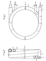
- the coaxial evaporator 1 shown consists of a helically coiled jacket tube 2 with internal evaporator tubes 3a.
- the free space between the casing tube 2 and the evaporator tubes 3a is flowed through by a heat exchange medium, for example water, which is introduced via an inlet connection 4, led out via an outlet connection 5 and is guided in counterflow to a refrigerant 6 in the evaporator tubes 3a.
- a heat exchange medium for example water
- a downwardly bent distributor housing 7 is arranged, which forms a closed pot and, in the exemplary embodiment shown, consists of a pipe bend 8 with a bottom cap 9 inserted in a pressure-tight manner.
- the individual evaporator tubes 3a in the casing tube 2 are extended by curved evaporator tubes 3b, which are guided with predetermined bending radii into the lower space of the distributor housing 7 and end at a distance a, which is preferably 20 to 45 mm, above the base cap 9.
- the distributor pipes 3b are bundled and their ends 10 are cut off at an angle ⁇ , which is preferably 30 to 45 °, rising obliquely from the inside to the outside.
- an injection pipe 11 is inserted into the distributor housing 7 above the bottom cap 9 of the pipe bend 8.
- the longitudinal axis of the injection pipe 11 is approximately aligned with the longitudinal axis of the casing pipe 2.
- the distance b is therefore at least twice the distance a.
- the distributor housing 7 is sealed off from the casing tube 2 with a perforated disk 13 in which the evaporator tubes 3a are fixed.
- Fig. 3 shows a practical embodiment in which the manifolds 3b are prefabricated and fixed in a spacer 12. Through the attached distributor housing 7, the spacer 12 also seals against the casing tube 2.
- the gas-liquid mixture of the refrigerant 6 is introduced through the injection pipe 11 into the distributor housing 7, in which a sump is formed from the liquid phase due to the higher specific weight.
- the gaseous phase of the refrigerant is present above the sump.
- the liquid level of the sump fluctuates between the lower and the upper end of the tapered ends 10 of the evaporator tubes 3b.
- the gaseous phase and the liquid phase of the mixture are evenly distributed into the same partial streams on the different evaporator tubes 3a and 3b.
Landscapes
- Engineering & Computer Science (AREA)
- Physics & Mathematics (AREA)
- Mechanical Engineering (AREA)
- Thermal Sciences (AREA)
- General Engineering & Computer Science (AREA)
- Chemical & Material Sciences (AREA)
- Chemical Kinetics & Catalysis (AREA)
- Heat-Exchange Devices With Radiators And Conduit Assemblies (AREA)
- Physical Deposition Of Substances That Are Components Of Semiconductor Devices (AREA)
- Vaporization, Distillation, Condensation, Sublimation, And Cold Traps (AREA)
Priority Applications (1)
| Application Number | Priority Date | Filing Date | Title |
|---|---|---|---|
| AT81108787T ATE13093T1 (de) | 1980-11-21 | 1981-10-23 | Verteilervorrichtung. |
Applications Claiming Priority (2)
| Application Number | Priority Date | Filing Date | Title |
|---|---|---|---|
| DE3043900 | 1980-11-21 | ||
| DE3043900A DE3043900C2 (de) | 1980-11-21 | 1980-11-21 | Verteilervorrichtung für Kältemittel |
Publications (3)
| Publication Number | Publication Date |
|---|---|
| EP0052773A2 true EP0052773A2 (fr) | 1982-06-02 |
| EP0052773A3 EP0052773A3 (en) | 1982-09-22 |
| EP0052773B1 EP0052773B1 (fr) | 1985-05-02 |
Family
ID=6117266
Family Applications (1)
| Application Number | Title | Priority Date | Filing Date |
|---|---|---|---|
| EP81108787A Expired EP0052773B1 (fr) | 1980-11-21 | 1981-10-23 | Dispositif de distribution |
Country Status (3)
| Country | Link |
|---|---|
| EP (1) | EP0052773B1 (fr) |
| AT (1) | ATE13093T1 (fr) |
| DE (1) | DE3043900C2 (fr) |
Cited By (1)
| Publication number | Priority date | Publication date | Assignee | Title |
|---|---|---|---|---|
| EP0172336A1 (fr) * | 1984-08-24 | 1986-02-26 | GebràDer Sulzer Aktiengesellschaft | Dispositif pour répartir uniformément un mélange à deux phases |
Family Cites Families (6)
| Publication number | Priority date | Publication date | Assignee | Title |
|---|---|---|---|---|
| US220595A (en) * | 1879-10-14 | Improvement in tapping and venting barrels | ||
| US2063380A (en) * | 1935-10-18 | 1936-12-08 | Peerless Ice Machine Company | Refrigerant distributor |
| US2193696A (en) * | 1937-08-23 | 1940-03-12 | Young Radiator Co | Distributor head for evaporators |
| US2220595A (en) * | 1938-11-17 | 1940-11-05 | Young Radiator Co | Distributor head for evaporators |
| US2196858A (en) * | 1938-12-03 | 1940-04-09 | Chrysler Corp | Distributor head |
| DE2731279C2 (de) * | 1977-07-11 | 1986-07-17 | KÜBA Kühlerfabrik Heinrich W. Schmitz GmbH, 8021 Baierbrunn | Vorrichtung zum Verteilen eines strömenden Flüssigkeits-Gas-Gemisches in mehrere Teilströme |
-
1980
- 1980-11-21 DE DE3043900A patent/DE3043900C2/de not_active Expired
-
1981
- 1981-10-23 AT AT81108787T patent/ATE13093T1/de active
- 1981-10-23 EP EP81108787A patent/EP0052773B1/fr not_active Expired
Cited By (1)
| Publication number | Priority date | Publication date | Assignee | Title |
|---|---|---|---|---|
| EP0172336A1 (fr) * | 1984-08-24 | 1986-02-26 | GebràDer Sulzer Aktiengesellschaft | Dispositif pour répartir uniformément un mélange à deux phases |
Also Published As
| Publication number | Publication date |
|---|---|
| DE3043900A1 (de) | 1982-07-22 |
| ATE13093T1 (de) | 1985-05-15 |
| DE3043900C2 (de) | 1983-01-05 |
| EP0052773A3 (en) | 1982-09-22 |
| EP0052773B1 (fr) | 1985-05-02 |
Similar Documents
| Publication | Publication Date | Title |
|---|---|---|
| EP2472211A2 (fr) | Dispositif de répartition et dispositif d'échangeur de chaleur | |
| DE19727493C2 (de) | Heizungsvorrichtung mit einer Wärmepumpe und einer Erdsonde | |
| DE2116982A1 (de) | Rohrleitungsverteileranlage für Vor- und Rücklaufleitungen, insbesondere für Warmwasser-Heizungsanlagen | |
| DE3513936C2 (de) | Kühleinrichtung für einen mehrstufigen Verdichter | |
| DE69102164T2 (de) | Wärmeaustauschvorrichtung, insbesondere für hybride, nichtazeotrope Arbeitsmedien verwendende Wärmepumpen. | |
| DE3026954C2 (de) | Wärmetauschvorrichtung | |
| DE69315199T2 (de) | Flüssigkeitsdurchströmtes verdichtersystem unter verwendung eines flüssigkeitsabscheiders | |
| DE2323678A1 (de) | Reaktor fuer die ammoniaksynthese | |
| EP0052773A2 (fr) | Dispositif de distribution | |
| DE3611696C2 (fr) | ||
| DE3522954A1 (de) | Verdampfer fuer ein kuehlsystem in form eines waermeaustauschers | |
| DE3304420A1 (de) | Schornsteinkessel | |
| DE3429366C2 (de) | Spaltgaskühler | |
| DE1901475A1 (de) | Vorrichtung zum Verteilen einer Zweiphasenstroemung auf Plattenwaermeaustauscher | |
| DE2611454A1 (de) | Abtreibkolonne | |
| DE2912011A1 (de) | Heizungskessel | |
| DE69805841T2 (de) | Flüssigkeitserhitzer | |
| DE2009377A1 (de) | Honzontalbefeuerter Wärmeaustauscher | |
| DE3129887C2 (fr) | ||
| DE3122520C2 (fr) | ||
| DE2437195B2 (de) | Vorrichtung zum Trocknen eines komprimierten Gases | |
| DE19517633A1 (de) | Kühlgerät für die Wetterkühlung in bergbaulichen Untertagebetrieben | |
| DE1938043A1 (de) | Durchlaufkessel | |
| DE807813C (de) | Vorrichtung zum Abtrennen von mindestens einer Komponente aus einem Fluessigkeitsgemisch durch Destillation | |
| DE711618C (de) | Fliehkraftabscheider fuer fluessige oder gasfoermige Gemische, die spezifisch verschieden schwere Bestandteile enthalten |
Legal Events
| Date | Code | Title | Description |
|---|---|---|---|
| PUAI | Public reference made under article 153(3) epc to a published international application that has entered the european phase |
Free format text: ORIGINAL CODE: 0009012 |
|
| AK | Designated contracting states |
Designated state(s): AT BE CH FR GB IT SE |
|
| PUAL | Search report despatched |
Free format text: ORIGINAL CODE: 0009013 |
|
| AK | Designated contracting states |
Designated state(s): AT BE CH FR GB IT SE |
|
| 17P | Request for examination filed |
Effective date: 19820810 |
|
| ITF | It: translation for a ep patent filed | ||
| GRAA | (expected) grant |
Free format text: ORIGINAL CODE: 0009210 |
|
| AK | Designated contracting states |
Designated state(s): AT BE CH FR GB IT LI SE |
|
| REF | Corresponds to: |
Ref document number: 13093 Country of ref document: AT Date of ref document: 19850515 Kind code of ref document: T |
|
| ET | Fr: translation filed | ||
| PLBE | No opposition filed within time limit |
Free format text: ORIGINAL CODE: 0009261 |
|
| STAA | Information on the status of an ep patent application or granted ep patent |
Free format text: STATUS: NO OPPOSITION FILED WITHIN TIME LIMIT |
|
| 26N | No opposition filed | ||
| ITTA | It: last paid annual fee | ||
| PGFP | Annual fee paid to national office [announced via postgrant information from national office to epo] |
Ref country code: BE Payment date: 19930930 Year of fee payment: 13 |
|
| PGFP | Annual fee paid to national office [announced via postgrant information from national office to epo] |
Ref country code: GB Payment date: 19931013 Year of fee payment: 13 |
|
| PGFP | Annual fee paid to national office [announced via postgrant information from national office to epo] |
Ref country code: SE Payment date: 19931018 Year of fee payment: 13 |
|
| PG25 | Lapsed in a contracting state [announced via postgrant information from national office to epo] |
Ref country code: GB Effective date: 19941023 |
|
| PG25 | Lapsed in a contracting state [announced via postgrant information from national office to epo] |
Ref country code: SE Effective date: 19941024 |
|
| PG25 | Lapsed in a contracting state [announced via postgrant information from national office to epo] |
Ref country code: BE Effective date: 19941031 |
|
| EAL | Se: european patent in force in sweden |
Ref document number: 81108787.3 |
|
| BERE | Be: lapsed |
Owner name: R. & G. SCHMOLE METALLWERKE G.M.B.H. & CO. K.G. Effective date: 19941031 |
|
| GBPC | Gb: european patent ceased through non-payment of renewal fee |
Effective date: 19941023 |
|
| EUG | Se: european patent has lapsed |
Ref document number: 81108787.3 |
|
| PGFP | Annual fee paid to national office [announced via postgrant information from national office to epo] |
Ref country code: FR Payment date: 19991022 Year of fee payment: 19 |
|
| PGFP | Annual fee paid to national office [announced via postgrant information from national office to epo] |
Ref country code: AT Payment date: 19991025 Year of fee payment: 19 |
|
| PGFP | Annual fee paid to national office [announced via postgrant information from national office to epo] |
Ref country code: CH Payment date: 19991027 Year of fee payment: 19 |
|
| PG25 | Lapsed in a contracting state [announced via postgrant information from national office to epo] |
Ref country code: AT Free format text: LAPSE BECAUSE OF NON-PAYMENT OF DUE FEES Effective date: 20001023 |
|
| PG25 | Lapsed in a contracting state [announced via postgrant information from national office to epo] |
Ref country code: LI Free format text: LAPSE BECAUSE OF NON-PAYMENT OF DUE FEES Effective date: 20001031 Ref country code: CH Free format text: LAPSE BECAUSE OF NON-PAYMENT OF DUE FEES Effective date: 20001031 |
|
| REG | Reference to a national code |
Ref country code: CH Ref legal event code: PL |
|
| PG25 | Lapsed in a contracting state [announced via postgrant information from national office to epo] |
Ref country code: FR Free format text: LAPSE BECAUSE OF NON-PAYMENT OF DUE FEES Effective date: 20010629 |
|
| REG | Reference to a national code |
Ref country code: FR Ref legal event code: ST |