EP0052832B1 - Control-head for pneumatic springs, particularly for adjusting seats of sitting furniture - Google Patents
Control-head for pneumatic springs, particularly for adjusting seats of sitting furniture Download PDFInfo
- Publication number
- EP0052832B1 EP0052832B1 EP81109614A EP81109614A EP0052832B1 EP 0052832 B1 EP0052832 B1 EP 0052832B1 EP 81109614 A EP81109614 A EP 81109614A EP 81109614 A EP81109614 A EP 81109614A EP 0052832 B1 EP0052832 B1 EP 0052832B1
- Authority
- EP
- European Patent Office
- Prior art keywords
- control
- housing
- shift
- pneumatic
- guide
- Prior art date
- Legal status (The legal status is an assumption and is not a legal conclusion. Google has not performed a legal analysis and makes no representation as to the accuracy of the status listed.)
- Expired
Links
Images

Classifications
-
- A—HUMAN NECESSITIES
- A47—FURNITURE; DOMESTIC ARTICLES OR APPLIANCES; COFFEE MILLS; SPICE MILLS; SUCTION CLEANERS IN GENERAL
- A47C—CHAIRS; SOFAS; BEDS
- A47C3/00—Chairs characterised by structural features; Chairs or stools with rotatable or vertically-adjustable seats
- A47C3/20—Chairs or stools with vertically-adjustable seats
- A47C3/30—Chairs or stools with vertically-adjustable seats with vertically-acting fluid cylinder
Definitions
- the invention relates to a control head for gas spring actuation, in particular for the seat plate adjustment on seating.
- Gas springs are used in seating, such as chairs, armchairs, vehicle seats and the like, both for the seat height adjustment and for the seat inclination adjustment. While the ejection force of the gas spring piston rod is usually only used for the upward movement of the unloaded seat plate and the piston rod is blocked after setting the desired seat height when adjusting the seat height, the damping-free mobility of the gas spring piston rod in connection with the natural ejection tendency and enable a weighing or rocking effect in cooperation with other suspension elements.
- the spring ratios can be selected so that the seat arrangement remains "braked" in the current state of equilibrium.
- the control element of the gas spring must be pressed in permanently, which can lead to complicated locking and unlocking mechanisms on seating furniture or to operating difficulties when adjusting the inclination.
- the resulting inadequacies also include that a seating position that is currently perceived as pleasant is changed again with a slight shift in body weight.
- the free mobility of the seat arrangement which is often too extensive as a result of the described control difficulties, also has the consequence that the seat arrangement can move back to an optically or usefully unfavorable starting position after being fully relieved, and / or immediately starts moving again when reloaded.
- the object of the invention is therefore to provide a means which allows the user of the seating furniture to select the type of seat inclination adjustment on gas spring-supported seating furniture in any hunt of the seating plate by a momentary push of a button.
- control head to be actuated by an impulse control command for determining the mode of operation of a gas spring is proposed, which control head is characterized by patent claim 1. Embodiments thereof are defined by the dependent claims.
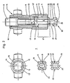
- 1A, 1B, 1 denotes the upper or piston rod-side end of a gas spring
- 2 the gas spring piston rod
- 3 the fastening end provided with a screw thread.
- This can be inserted directly, or, as shown, with the interposition of a threaded press-in bush 4 ', into the assembly opening 4 of the control head housing 5.
- the gas spring control rod is designated, which coaxially passes through the piston rod 2 and acts on one (not shown) gas spring valve arrangement.
- Fig. 1A the gas spring control rod 6 is in the ejected position (piston rod blocked), in Fig. 1 B, however, in the depressed position (piston rod "freely” movable).
- a locking mechanism, generally designated 7, in the interior of the control head housing 5 defines these two positions of the control rod 6, as will be described in detail later. From this latching mechanism 7, the end 8 of a control sleeve 9, which is designed, for example, in the form of a push button, also protrudes below the upper housing end.
- protruding coupling members are designated, which can be designed as a pivot pin, for example, when the gas spring is suspended. It goes without saying that the housing 5, which in the design of the gas spring control head according to the invention which is firmly connected to the piston rod 2, can also be provided with differently designed connection means.
- the housing 5 shown in more detail in FIG. 2 contains a continuous cylindrical recess 11 with a connection section 12 containing the already mentioned assembly opening 4, a (central) guide zone 13 and a centering and coupling section 14 on the actuating side.
- the one on the left in FIG. 2 the vertical sectional view shown plan view or front view shows the housing 5 seen from the piston rod side.
- the (middle) guide zone 13 preferably has a number of two to four guide cams 15 which are directed radially inward via a narrowed, offset base bore 13 'and which are arranged uniformly distributed over the circumference of the base bore 13' and are spaced apart from one another by an axially oriented guide groove 16 .
- the guide cams 15 are provided on their axial end facing the connection section 12 with locking teeth 17, the peripheral profile of which best emerges from FIGS. 3a-c and will be explained later with reference to these figures.
- a centering and stop sleeve 18 is pressed into the base bore 13 '.
- the sleeve 18 serves both as a movement limiting element for the control sleeve 9 already mentioned in the latching mechanism 7 and also for centering the end 8 of the control sleeve 9 in the housing 5 designed as a pushbutton element.
- a differently designed centering and stop means can also be provided. If necessary, a reduction of the base bore 13 ′ that extends at least over part of the sleeve length can also be provided, the movement stop for the control sleeve 9 having to be provided, for example, at the outer ends of the guide grooves 16.
- the control sleeve 9 is displaceably mounted in the central section of the cylindrical recess 11 located within the guide cams 15 in the housing 5 and, as the relevant front view to the left of the side view of the guide area 9 'shows, corresponding axially oriented guide wedges 19 corresponding to guide area 9', which engage in the guide grooves 16 between the cams 15 and secure the control sleeve 9 against rotation in the housing 5.
- the control sleeve 9 also has a central blind hole 20 and has on its opening side a toothing 21, the peripheral profile of which is shown in FIGS. 3a-c and will be explained in detail later.
- the switching element 23 (see also FIGS. 1A, 1B) contains a switching head 24 formed on one end of the centering pin 22, consisting of a disk-shaped stop plate 25 and centering pin 22, axially oriented switching wedges 26 formed uniformly distributed.
- the switching wedges 26 are like the associated front view 2 to the left of the switching element 23 shown in side view in the main illustration of FIG. 2 shows, just as the guide wedges 19 are dimensioned such that they can be partially inserted into the guide grooves 16 and thereby secure the switching element 23 in the cylindrical recess 11 in the housing 5 against rotation .
- the ends of the switching wedges 26 facing the centering pin 22 are provided with inclined switching surfaces 27.
- the inclined surfaces 27 are oriented in the same direction as viewed in the circumferential direction and work together with the locking teeth 17 on the guide cams 15 and on the transport teeth 21 of the control sleeve 9 in the manner described below with reference to FIGS. 3a-c.
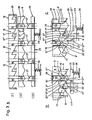
- FIG. 3a shows schematically and in an exploded view, which is only intended for explanatory purposes, the developments of: (I) the guide cams 15 spaced apart by the guide grooves 16 and their locking teeth 17 in the interior of the control head housing 5, (11) the guide region 9 'of the control sleeve 9 with the guide wedges 19 arranged thereon and the end toothing 21; and (111) the switching element 23 or the switching head 24 with the switching wedges 26 arranged thereon, including the oblique switching surfaces 27, and the stop plate 25.
- the housing containing the guide zone 13 will be described below in accordance with the arrangement of the mechanical parts in the control head and the related construction details 5 as "fixed" component (1), the control sleeve 9 designated as (11) as the actuating member, and the switching element 23 designated as (111) generally referred to as the control member.
- the (longer) tooth surface 17 'of the locking toothing 17 in the fixed component is referred to as the locking surface and the (shorter) tooth surface 17 "is referred to as the sliding surface.
- the tooth surfaces 17 ', 17 "and the inclined surfaces 21' are clearly effective here as cam follower surfaces.
- the spring symbols 28 are intended to indicate that the switching element 23 is always operationally under a pressure force exerted by the gas spring control rod 6 (FIGS. 1A, 1 B), which is supported on the housing 5 via the piston rod end 3.
- FIG. 3b The components of the control head symbolized and drawn apart in FIG. 3a with (I), (11) and (111) are shown in solid lines in FIG. 3b in the locked position of the gas spring piston rod 2 (FIGS. 1A, 1B), in which the control rod 6 is ejected.
- the switching element 23 is pushed into its inserted position in the locking mechanism 7.
- the switching wedge 26 In this position of the components 1, 11 and 111, the switching wedge 26 is caught in the guide groove 16, and its inclined surface 27 lies against the relative feed surface 21 'of the transport toothing 21 on the actuating member (control sleeve 9), which in turn via the Free ends 30 of the wedges 19 is supported on the stop shoulder 29 fixed to the housing.
- control head described above for the actuation of the control elements of a gas spring thus makes it possible, in a compact arrangement, to provide a latching mechanism 7 with which the two working methods of the gas spring can be selected by pulse actuation: piston rod "blocked” and piston rod “freely movable” can be selected. It is essential that the control head according to the invention can be firmly attached as a self-contained device on the piston rod 2 of the gas spring, and that the mode of operation of the gas spring selected by pulse actuation is maintained after the preselection has been made without external force or control action.
- This impulse actuation can of course take place in the manner of a push button actuation as well as by other actuation means such as piston-cylinder units or by electromechanical means.
- the anti-rotation lock of the control sleeve 9 could be achieved with a single guide wedge 19 or with a cross-sectional shape that generally deviates from around.
- the locking of the switching element 23 can be achieved with differently designed locking zones in the locking teeth 17 fixed to the housing. Finally, this can be profiled in such a way that when switching element 23 is shifted forward, it moves to the right.
Landscapes
- Fluid-Damping Devices (AREA)
Abstract
Description
Die Erfindung bezieht sich auf einen Steuerkopf für Gasfederbetätigung, insbesondere für die Sitzplattenverstellung an Sitzmöbeln.The invention relates to a control head for gas spring actuation, in particular for the seat plate adjustment on seating.
Gasfedern werden bei Sitzmöbeln, wie Stühlen, Sesseln, Fahrzeugsitzen und dergl., sowohl für die Sitzhöhenverstellung als auch für die Sitzflächenneigungseinstellung verwendet. Während bei der Sitzhöhenverstellung die Ausstosskraft der Gasfeder-Kolbenstange in der Regel nur für die Aufwärtsbewegung der unbelasteten Sitzplatte ausgenützt und die Kolbenstange nach Einstellung der gewünschten Sitzhöhe blockiert wird, kann bei der Sitzflächenneigungsverstellung die gedämpftfreie Beweglichkeit der Gasfeder-Kolbenstange in Verbindung mit der natürlichen Ausstosstendenz und im Zusammenwirken mit weiteren Federungselementen einen Wiege- oder Schaukeleffekt ermöglichen. Dabei können die Federverhältnisse so gewählt werden, dass die Sitzanordnung jeweils in dem sich momentan einspielenden Gleichgewichtszustand "gebremst" verharrt.Gas springs are used in seating, such as chairs, armchairs, vehicle seats and the like, both for the seat height adjustment and for the seat inclination adjustment. While the ejection force of the gas spring piston rod is usually only used for the upward movement of the unloaded seat plate and the piston rod is blocked after setting the desired seat height when adjusting the seat height, the damping-free mobility of the gas spring piston rod in connection with the natural ejection tendency and enable a weighing or rocking effect in cooperation with other suspension elements. The spring ratios can be selected so that the seat arrangement remains "braked" in the current state of equilibrium.
Zu beachten ist indessen, dass zur Erzielung dieser freien Beweglichkeit das Steuerorgan der Gasfeder dauernd eingedrückt sein muss, was zu komplizierten Sperr- und Freigabe-Mechanismen an Sitzmöbel oder zu Betätigungsschwierigkeiten bei der Neigungseinstellung führen kann. Zu den daraus resultierenden Unzulänglichkeiten gehört auch, dass eine als momentan angenehm empfundene Sitzstellung schon bei einer allenfalls geringfügigen Körpergewichtsverlagerung wieder verändert wird. Die infolge der beschriebenen Steuerungsschwierigkeiten vielfach zu weit gehende freie Beweglichkeit der Sitzanordnung hat auch zur Folge, dass sich die Sitzanordnung nach voller Entlastung in eine optisch oder benützungsmässig ungünstige Ausgangsstellung zurückbewegen kann, und/oder sich bei Wiederbelastung sofort wieder in Bewegung setzt.It should be noted, however, that in order to achieve this free mobility, the control element of the gas spring must be pressed in permanently, which can lead to complicated locking and unlocking mechanisms on seating furniture or to operating difficulties when adjusting the inclination. The resulting inadequacies also include that a seating position that is currently perceived as pleasant is changed again with a slight shift in body weight. The free mobility of the seat arrangement, which is often too extensive as a result of the described control difficulties, also has the consequence that the seat arrangement can move back to an optically or usefully unfavorable starting position after being fully relieved, and / or immediately starts moving again when reloaded.
Die Aufgabe der Erfindung besteht somit darin, ein Mittel zu schaffen, das es dem Benützer des Sitzmöbels erlaubt, die Art der Sitzneigungseinstellung an gasfedergestützten Sitzmöbeln in jeder beliebigen Jage der Sitzplatte durch einen momentanen Tastendruck auszuwählen.The object of the invention is therefore to provide a means which allows the user of the seating furniture to select the type of seat inclination adjustment on gas spring-supported seating furniture in any hunt of the seating plate by a momentary push of a button.
Zur Lösung dieser Aufgabe wird erfindungsgemäss ein durch einen Impulssteuerbefehl zu betätigender Steuerkopf für die Festlegung der Betriebsweise einer Gasfeder vorgeschlagen, welcher Steuerkopf durch den Patentanspruch 1 gekennzeichnet ist. Ausführungsformen davon sind durch die abhängigen Ansprüche definiert.To achieve this object, a control head to be actuated by an impulse control command for determining the mode of operation of a gas spring is proposed, which control head is characterized by
Ein Ausführungsbeispiel des erfindungsgemässen Steuerkopfes ist nachstehend anhand der Zeichnung erläutert. In dieser zeigt:
- Fig. 1A, 1 B den auf die Kolbenstange einer Gasfeder aufgesetzten Steuerkopf in A - blockierter und B = freibeweglicher Stellung der Kolbenstange, bei jeweils partiell geschnittenem Gehäuse und in Seitenansicht gezeigten teleskopisch ineinander greifenden Steuerteilen,
- Fig. 2 eine Schnittdarstellung des Steuerkopfes nach Fig. 1 in grösserem Maßstab, wobei die koaxial zueinander angeordneten Bauteile eines Verrastungsmechanismus auseinandergezogen dargestellt, und die für die einzelnen Bauteile charakteristischen Eingriffszonen jeweils links in der Figur einzeln in der jeweils funktionsmässig interessierenden Grundrissdarstellung gezeigt sind, und
- Fig. 3a, b und c die Eingriffszonen am Steuerkopf-Gehäuse und an den beiden teleskopierenden Steuerteilen in a) auseinandergezogener Abwicklung (Prinzipdarstellung), auf Nute-Keil ausgerichtet und vier Nuten-Keil-Eingriffsbereichen, b) beim Uebergang von der Steuerstellung "Kolbenstange blockiert" in die Steuerstellung "Kolbenstange frei", und c) beim Uebergang von der Steuerstellung "Kolbenstange frei" in die Steuerstellung "Kolbenstange blockiert", jeweils in Vorwärtsschaltrichtung zwischen benachbarten Nuten-Keil- bzw. Schrägfläche-Keil-Eingriffsbereichen, und jeweils einem Nuten-Keil-Eingriffsbereich.
- 1A, 1 B the control head placed on the piston rod of a gas spring in A - blocked and B = freely movable position of the piston rod, with a partially cut housing and a telescopically interlocking control parts shown in side view,
- 2 shows a sectional view of the control head according to FIG. 1 on a larger scale, the components of a latching mechanism arranged coaxially to one another being shown pulled apart, and the engagement zones which are characteristic of the individual components are shown individually on the left in the figure in the functional representation of the floor plan, and
- 3a, b and c, the engagement zones on the control head housing and on the two telescopic control parts in a) pulled-apart development (schematic diagram), aligned to the slot wedge and four slot-wedge engagement areas, b) at the transition from the control position "piston rod blocked "in the control position" piston rod free ", and c) at the transition from the control position" piston rod free "to the control position" piston rod blocked ", in each case in the forward switching direction between adjacent groove-wedge or inclined surface-wedge engagement areas, and one Groove-wedge engagement area.
In den Fig. 1A, 1 B bezeichnet 1 jeweils das obere bzw. kolbenstangenseitige Ende einer Gasfeder, 2 die Gasfeder-Kolbenstange, und 3 deren mit einem Schraubgewinde versehenes Befestigungsende. Dieses kann direkt, oder wie gezeigt unter Zwischenschaltung einer Gewinde-Einpressbüchse 4', in die Montageöffnung 4 des Steuerkopfgehäuses 5 eingesetzt sein. Mit 6 ist die Gasfeder-Steuerstange bezeichnet, welche die Kolbenstangs 2 koaxial durchsetzt und auf eins (nicht gezeigte) Gasfeder-Ventilanordnung einwirkt. In Fig. 1A befindet sich die Gasfeder-Steuerstange 6 in ausgestossener Stellung (Kolbenstange blockiert), in Fig. 1 B dagegen in eingedrückter Stellung (Kolbenstange "frei" beweglich). Ein allgemein mit 7 bezeichneter Verrastungsmechanismus im Innern des Steuerkopfgehäuses 5 legt diese beiden Stellungen der Steuerstange 6, wie später im Detail beschrieben, fest. Von diesem Verrastungsmechanismus 7 ragt das beispielsweise druckknopfförmig gestaltete Ende 8 einer ebenfalls nachstehend detailliert beschriebenen Steuerhülse 9 über das obere Gehäuseende hinaus.1A, 1B, 1 denotes the upper or piston rod-side end of a gas spring, 2 the gas spring piston rod, and 3 the fastening end provided with a screw thread. This can be inserted directly, or, as shown, with the interposition of a threaded press-in bush 4 ', into the assembly opening 4 of the
Mit 10 sind seitlich über das Steuerkopfgehäuse herausragende Kupplungsglieder bezeichnet, die beispielsweise bei pendelnder Aufhängung der Gasfeder als Gelenkzapfen gestaltet sein können. Es versteht sich, dass das Gehäuse 5, welches in der gezeigten Gestaltung des erfindungsgemässen Gasfeder-Steuerkopfes der der Kolbenstange 2 fest verbunden ist, auch mit anders gestalteten Anschlussmitteln versehen werden kann.With 10 laterally over the control head housing protruding coupling members are designated, which can be designed as a pivot pin, for example, when the gas spring is suspended. It goes without saying that the
Gestaltungsdetails und Arbeitsweise der Teile bei der in der Zeichnung gezeigten Ausführungsform des erfindungsgemässen Steuerkopfes werden nun anhand der Fig. 2 und 3a-c erläutert. Gleiche Referenzzeichen in den Figuren der Zeichnung bezeichnen gleiche oder funktionell übereinstimmende Bauteile.Design details and operation of the parts in the shown in the drawing Embodiment of the control head according to the invention will now be explained with reference to FIGS. 2 and 3a-c. Identical reference symbols in the figures of the drawing denote identical or functionally identical components.
Das in Fig. 2 mit mehr Details dargestellte Gehäuse 5 enthält eine durchgehende zylindrische Ausnehmung 11 mit einem die bereits erwähnte Montageöffnung 4 enthaltenden Anschlussabschnitt 12, einer (mittleren) Führungszone 13 und einem betätigungsseitigen Zentrier- und Ankupplungsabschnitt 14. Die in Fig. 2 links von der Vertikalschnittdarstellung gezeigte Grundriss- oder Stirnseitenansicht zeigt das Gehäuse 5 von der Kolbenstangenseite her gesehen.The
Die (mittlere) Führungszone 13 weist eine Anzahl vorzugsweise zwei bis vier über eine verengt-abgesetzte Basisbohrung 13' radial einwärts gerichtete Führungsnocken 15 auf, die über den Umfang der Basisbohrung 13' gleichmässig verteilt angeordnet und jeweils durch eine axial orientierte Führungsnute 16 voneinander distanziert sind. Die Führungsnocken 15 sind auf ihrem dem Anschlussabschnitt 12 zugewandten axialen Ende mit einer Rastverzahnung 17 versehen, deren peripheres Profil am besten aus den Fig. 3a-c hervorgeht und anhand dieser Figuren später erläutert wird. Am andern axialen Ende der Führungsnocken 15 ist eine Zentrier- und Anschlaghülse 18 in die Basisbohrung 13' eingepresst. Die Hülse 18 dient sowohl als Bewegungsbegrenzungselement für die bereits erwähnte Steuerhülse 9 im Verrastungsmechanismus 7, als auch zur Zentrierung des als Drucktastglied gestalteten Endes 8 der Steuerhülse 9 im Gehäuse 5. Anstelle der Hülse 18 kann auch ein anders gestaltetes Zentrier- und Anschlagmittel vorgesehen werden. Gegebenenfalls kann auch eine wenigstens über einen Teil der Hülsenlänge reichende Reduktion der Basisbohrung 13' vorgesehen sein, wobei der Bewegungsanschlag für die Steuerhülse 9 etwa bei den äusseren Enden der Führungsnuten 16 vorzusehen wäre.The (middle)
Die Steuerhülse 9 ist in dem innerhalb der Führungsnocken 15 liegenden zentralen Abschnitt der zylindrischen Ausnehmung 11 im Gehäuse 5 verschiebbar gelagert und weist, wie die bezügliche Stirnansicht links neben der Seitenansicht des Führungsbereiches 9' zeigt, entsprechend Führungsbereich 9' reichende axial orientierte Führungskeile 19 auf, die in die Führungsnuten 16 zwischen den Nocken 15 eingreifen und die Steuerhülse 9 gegen Verdrehen im Gehäuse 5 sichern. Die Steuerhülse 9 besitzt ferner eine zentrale Sacklochbohrung 20 und weist auf deren Oeffnungsseite eine Transportverzahnung 21 auf, deren peripheres Profil aus den Fig. 3a-c hervorgeht und später im Detail erläutert wird.The
In der Sackloch-Bohrung 20 ist der Zentrierzapfen 22 eines Schaltgliedes 23 drehbar gelagert. Das Schaltglied 23 (siehe auch Fig. 1A, 1B) enthält einen am einen Ende des Zentrierzapfens 22 angeformten Schaltkopf 24, bestehend aus einer scheibenförmigen Anschlagplatte 25 und Zentrierzapfens 22 gleichmässig verteilt angeformten axial orientierten Schaltkeilen 26. Die Schaltkeile 26 sind, wie die zugeordnete Stirnansicht links von dem in der Hauptdarstellung der Fig. 2 in Seitenansicht gezeigten Schaltglied 23 zeigt, gleich wie die Führungskeile 19 so dimensioniert, dass sie einesteils in die Führungsnuten 16 einschiebbar sind und dabei das Schaltglied 23 in der zylindrischen Ausnehmung 11 im Gehäuse 5 gegen Verdrehen sichern. Andernteils zentrieren sie das Schaltglied 23 wenn es sich ausserhalb der Führungsnuten 16 befindet und sich dabei in der zylindrischen Ausnehmung 11 im Gehäuse 5 frei drehen kann. Die den Zentrierzapfen 22 zugewandten Enden der Schaltkeile 26 sind mit schrägen Schaltanflächungen 27 versehen. Die Schrägflächen 27 sind in Umlaufrichtung betrachtet gleichlaufend orientiert und arbeiten mit den Rastverzahnungen 17 an den Führungsnocken 15 und an der Transportverzahnung 21 der Steuerhülse 9 in der anhand der Fig. 3a-c nachstehend beschriebenen Weise zusammen.In the
Fig. 3a zeigt schematisch und in einer nur zu Erläuterungszwecken gedachten auseinandergezogenen Darstellungsweise die Abwicklungen von: (I) den durch die Führungsnuten 16 voneinander distanzierten Führungsnocken 15 und ihren Rastverzahnungen 17 im Innern des Steuerkopfgehäuses 5, (11) dem Führungsbereich 9' der Steuerhülse 9 mit den darauf angeordneten Führungskeilen 19 und der endseitigen Transportverzahnung 21; und (111) dem Schaltglied 23 bzw. dem Schaltkopf 24 mit den darauf angeordneten Schaltkeilen 26 inklusive den schrägen Schaltanflächungen 27, und der Anschlagplatte 25. Entsprechend der Anordnung der mechanischen Teile im Steuerkopf bzw. der bezüglichen Konstruktionsdetails wird nachfolgend das die Führungszone 13 enthaltende Gehäuse 5 als "festes" Bauteil (1), die mit (11) bezeichnete Steuerhülse 9 als Betätigungsorgan, und das mit (111) bezeichnete Schaltglied 23 allgemein als Steuerorgan bezeichnet. Weiterhin werden entsprechend ihren aus den Fig. 3b und 3c erkennbaren Punktionen die (längere) Zahnfläche 17' der Rastverzahnung 17 im festen Bauteil als Rastfläche, und die (kürzere) Zahnfläche 17" als Gleitfläche bezeichnet. Desgleichen werden die Schrägflächen 21' der Transportverzahnung 21 an der Steuerhülse 9 als Vorschubfläche, und die bezügliche des Schaltvorgangs passive Gegenschrägung 21" als Stoppfläche benannt. Die Zahnflächen 17', 17" und die Schrägflächen 21' sind hier deutlich als Nockenfolgeflächen wirksam.3a shows schematically and in an exploded view, which is only intended for explanatory purposes, the developments of: (I) the
Die Federsymbole 28 sollen darauf hinweisen, dass das Schaltglied 23 betriebsmässig stets unter einer von der Gasfeder-Steuerstange 6 (Fig. 1A, 1 B) ausgeübten Andruckkraft steht, die über das Kolbenstangenende 3 am Gehäuse 5 abgestützt ist. Desgleichen bezeichnet 29 am "festen" Bauteil (I) die Anschlagschulter an der Zentrier- und Anschlaghülse 18 (Fig. 2), und 30 die freien Enden der Führungskeile 19 an der Steuerhülse 9, welche Enden in der Schaltstellung nach Fig. 3b wie nachstehend beschrieben gegen die Hülse 18 bewegungsbegrenzend anliegen.The
Die in Fig. 3a mit (I), (11) und (111) symbolisierten und auseinandergezogen gezeigten Bauteile des Steuerkopfes sind in Fig. 3b mit ausgezogenen Linien in der Blockierstellung der Gasfeder- Kolbenstange 2 (Fig. 1A, 1 B) gezeigt, in welcher die Steuerstange 6 ausgestossen ist. Entsprechend ist das Schaltglied 23 in seine eingeschobene Stellung im Verrastungsmechanismus 7 gedrängt. In dieser Stellung der Bauteile 1, 11 und 111 befindet sich der Schaltkeil 26 in der Führungsnute 16 gefangen, und seine Schrägfläche 27 liegt gegen die bezügliche Vorschubfläche 21' der Transportverzahnung 21 am Betätigungsorgan (Steuerhülse 9) an, das (die) ihrerseits über die freien Enden 30 der Keile 19 an der gehäusefesten Anschlagschulter 29 abgestützt ist.The components of the control head symbolized and drawn apart in FIG. 3a with (I), (11) and (111) are shown in solid lines in FIG. 3b in the locked position of the gas spring piston rod 2 (FIGS. 1A, 1B), in which the
Hier sei darauf hingewiesen, dass für die Erläuterung der Schaltgliedbewegungen nach den Fig. 3a und 3b jeweils nur ein Schaltkeil 26 und nur die diesem in der betrachteten Stellung benachbarten Partien der Rastverzahnung 17 und der Transportverzahnung 21 angefürht werden. Es versteht sich, dass an jedem der Schaltkeile 26/Fig. 3a die gleichen Bewegungs- und Eingriffsverhältnisse auftreten.It should be pointed out here that for the explanation of the switching element movements according to FIGS. 3a and 3b, only one switching
Wird das Betätiguhgsorgan II = Steuerhülse 9 in Pfeilrichtung A abwärts gedrängt, so wird der Schaltkeil 26 durch den Eingriff der Schrägflächen 21', 27 nach unten aus der Führungsnute 16 herausgeschoben. Sobald der Schaltkeil 26 die Nute 16 verlässt, gleitet seine Schrägfläche 27 auf der Schrägfläche 21' bzw. 21 + nach links in die mit unterbrochenen Linien gezeigte Anschlagstellung zwischen den Steuerhülsen-Schrägflächen 21 + und 21 + +. Lässt man nun das Betätigungsorgan II gemäss Pfeil B in seine Ausgangslage zurückgleiten, so gelangt die Schrägfläche 27 bzw. 27 + am ausgeschobenen Schaltkeil 26 zunächst mit dem höhern Ende der Rastfläche 17' in Berührung und gleitet dann unter Einwirkung der Federkraft 28 dieser Fläche entlang nach links-aufwärts in die mit strichpunktierten Linien gezeigte weitere Keil-Stellung. In dieser Stellung ruht die Schrägfläche 27+ + auf der Schrägfläche 17' des "festen" Bauteils (I) und der Schaltkeil 26' liegt links an der Anschlagfläche 17+ der Rastverzahnung 17 an. Diese Stellung entspricht etwa einer Mittellage zwischen zwei benachbarten Führungsnuten, wobei das Schaltglied 23' um das Mass h aus seiner Ausgangslage ausgeschoben ist. Der Weg h ist so bemessen, dass die Gasfeder-Steuerstange 6 (Fig. 1 A, 1 B) die Arbeitsweise der Kolbenstange 2 auf "frei beweglich" umschaltet.If the actuating member II =
Kurz: durch einen impulsförmigen Druck auf das druckknopfförmige Ende 8 der Steuerhülse 9 wird der in der Führungsnute 16 liegende Schaltkeil 26 aus der Nute 16 herausgeschoben und das Schaltglied 23 hierauf unter Einwirkung der Rückstosskraft (symbolisch: Feder 28) der Gasfeder-Steuerstange 6 mit einer Links-Drehbewegung in eine Zwischenraststellung auf der Transportverzahnung 21 der Steuerhülse 9 gebracht. Nach Loslassen des Druckes auf die Steuerhülse 9 gleitet der Schaltkeil 26 längs der Rastfläche 17' am Steuerkopfgehäuse 5 in eine "ausgestossene" (stabile) Zwischen-Raststellung, in welcher die Gasfeder-Kolbenstange 2 nun frei beweglich ist.In short: by a pulsed pressure on the push-button-shaped
Die Rückschaltung aus der "ausgestossenen" (stabilen) Zwischen-Raststellung gemäss Fig. 3b in die ebenfalls "stabile" eingefahrene Stellung des Schaltgliedes 23 wird nun anhand der Fig. 3c erläutert. Gleiche Referenzzeichen wie in Fig. 3b bezeichnen gleiche Konstruktionsoder Funktionselemente. Die strichpunktierte Endlage des Schaltkeils 26' in Fig. 3b entspricht der mit ausgezogenen Linien gezeigten Ausgangslage des Schaltkeils 26 in Fig. 3c.The downshift from the "ejected" (stable) intermediate detent position according to FIG. 3b to the likewise "stable" retracted position of the switching
Drückt man das Betätigungsorgan II = Steuerhülse 9 durch Druck auf ihr Ende 8 in Pfeilrichtung A' abwärts, so wird der Schaltkeil 26 durch den Eingriff der Schrägflächen 21', 27 längs der Anschlagfläche 17+ nach unten geschoben. Sobald der Schaltkeil 26 ausser Eingriff mit der Anschlagfläche 17+ gelangt, gleitet seine Schrägfläche 27 auf der Vorschubfläche 21' bzw. 21 + nach links in die mit unterbrochenen Linien gezeigte Anschlagstellung zwischen den Steuerhülsen-Schrägflächen 21 + und 21 + +.If the actuating member II =
Lässt man nun das Betätigungsorgan II gemäss Pfeil B' in seine Ausgangslage zurückgleiten, so gelangt die Schrägfläche 27 bzw. 27 + am ausgeschobenen Schaltkeil 26' zunächst mit der schrägen Gleitfläche 17" der gehäusefesten Rastverzahnung 17 in Berührung und gleitet dann unter Einwirkung der Federkraft 28 der Gleitfläche 17" entlang nach links-aufwärts in die mit strichpunktierten Linien gezeigte Stellung in der Nut 16. In dieser Stellung ruht die Schrägfläche 27 auf der Vorschubfläche 21' der Transportverzahnung 21. Diese Stellung des Schaltkeils 26 bzw. des Schaltgliedes 23 entspricht im Prinzip der Ausgangsstellung nach Fig. 3b, wobei das Schaltglied 23' wieder um das Mass h weiter in den Verrastungsmechanismus 7 eingetaucht ist. Die Gasfeder-Steuerstange 6 (Fig. 1A, 1B) ist wieder entlastet und die Kolbenstange 2 ist auf "blockiert" umgeschaltet.If the actuating element II is now slid back into its starting position according to arrow B ', then the
Kurz: durch einen weitern impulsförmigen Druck auf das Ende 8 der Steuerhülse 9 wird der Schaltkeil 26 aus seiner "ausgestossenen" Zwischen-Raststellung in der Rastverzahnung 17 herausgeschoben. Unter Einwirkung der Rückstosskraft (symbolisch: Feder 28) der Gasfeder-Steuerstange 6 wird das Schaltglied 23 längs der Steuerhülsen-Schrägfläche 21 + auf die Gleitfläche 17" der gehäusefesten Rastverzahnung 17 gebracht. Nach Loslassen des Druckes auf die Steuerhülse 9 gleitet der Schaltkeil 26 längs der Gleitfläche 17" unter weiterer Einwirkung der Rückstosskraft der Gasfeder-Steuerstange 6 und Fortsetzung der Links-Drehbewegung in die nächstliegende Führungsnute 16 der gehäusefesten Rastverzahnung 17 hinein. Weil dabei die Gasfeder-Steuerstange 6 entlastet wird, schaltet sie die (nicht gezeigte) Gasfeder-Ventilanordnung in die Stellung "Kolbenstange blockiert" um.In short: by a further pulse-shaped pressure on the
Der vorstehend beschriebene Steuerkopf für die Betätigung der Steuerorgane einer Gasfeder ermöglicht somit in einer kompakten Anordnung einen Verrastungsmechanismus 7 zu schaffen, mit welchem durch Impulsbetätigung die beiden Arbeitsweisen der Gasfeder: Kolbenstange "blockiert" und Kolbenstange "frei beweglich" vorwählbar sind. Von wesentlicher Bedeutung ist, dass der erfindungsgemässe Steuerkopf als in sich geschlossene Vorrichtung auf der Kolbenstange 2 der Gasfeder fest aufsetzbar ist, und dass die durch Impulsbetätigung ausgewählte Arbeitsweise der Gasfeder nach getroffener Vorwahl ohne äussere Kraft- oder Steuereinwirkung aufrechterhalten wird. Diese Impulsbetätigung kann selbstverständlich sowohl in der Art einer Druckknopfbetätigung als auch durch andere Betätigungsmittel wie Kolben-Zylinder-Aggregate oder auf elektromechanischem Weg erfolgen.The control head described above for the actuation of the control elements of a gas spring thus makes it possible, in a compact arrangement, to provide a
Es versteht sich weiter, dass gegenüber der gezeigten Ausführungsform des erfindungsgemässen Steuerkopfes eine Anzahl Variationen möglich sind. So könnte beispielsweise die Verdrehsicherung der Steuerhülse 9 mit einem einzigen Führungskeil 19 oder mit einer allgemein von rund abweichenden Querschnittsform erzielt werden. Ebenso kann die Verrastung des Schaltgliedes 23 mit anders gestalteten Rastzonen in der gehäusefesten Rastverzahnung 17 erzielt werden. Diese kann schliesslich so profiliert sein, dass bei der Vorwärtsschaltung des Schaltgliedes 23 dieses nach rechts läuft.It is further understood that a number of variations are possible compared to the shown embodiment of the control head according to the invention. For example, the anti-rotation lock of the
Claims (11)
Priority Applications (1)
| Application Number | Priority Date | Filing Date | Title |
|---|---|---|---|
| AT81109614T ATE17436T1 (en) | 1980-11-21 | 1981-11-11 | CONTROL HEAD FOR GAS SPRING ACTUATION, PARTICULARLY FOR SEAT ADJUSTMENT ON SEAT FURNITURE. |
Applications Claiming Priority (2)
| Application Number | Priority Date | Filing Date | Title |
|---|---|---|---|
| CH8633/80A CH652902A5 (en) | 1980-11-21 | 1980-11-21 | CONTROL HEAD FOR ACTUATING THE CONTROL ROD OF THE VALVE ARRANGEMENT OF A GAS SPRING. |
| CH8633/80 | 1980-11-21 |
Publications (3)
| Publication Number | Publication Date |
|---|---|
| EP0052832A2 EP0052832A2 (en) | 1982-06-02 |
| EP0052832A3 EP0052832A3 (en) | 1983-04-20 |
| EP0052832B1 true EP0052832B1 (en) | 1986-01-15 |
Family
ID=4342877
Family Applications (1)
| Application Number | Title | Priority Date | Filing Date |
|---|---|---|---|
| EP81109614A Expired EP0052832B1 (en) | 1980-11-21 | 1981-11-11 | Control-head for pneumatic springs, particularly for adjusting seats of sitting furniture |
Country Status (4)
| Country | Link |
|---|---|
| EP (1) | EP0052832B1 (en) |
| AT (1) | ATE17436T1 (en) |
| CH (1) | CH652902A5 (en) |
| DE (1) | DE3173534D1 (en) |
Families Citing this family (13)
| Publication number | Priority date | Publication date | Assignee | Title |
|---|---|---|---|---|
| DE8320621U1 (en) * | 1983-07-16 | 1989-01-26 | Bürositzmöbelfabrik Friedrich-W. Dauphin GmbH & Co, 8561 Offenhausen | Gas spring, especially for adjusting the backrests of chairs, such as office swivel chairs, etc. |
| DE3602441A1 (en) * | 1986-01-28 | 1987-07-30 | Bauer Fritz & Soehne Ohg | LENGTH ADJUSTABLE GAS SPRINGS WITH PERMANENT RELEASE DEVICE |
| CH676417A5 (en) * | 1988-07-15 | 1991-01-31 | Giroflex Entwicklungs Ag | |
| DE4235435A1 (en) * | 1992-10-21 | 1994-04-28 | Martin Steifensand Sitzmoebel | Seat supports for seating |
| DE19502649A1 (en) * | 1995-01-28 | 1996-08-01 | Stoll Kg Christof | Locking mechanism for the reclining back of a chair |
| US5577804A (en) * | 1995-06-30 | 1996-11-26 | Global Upholstery Company | Seat height adjustment mechanism for a chair |
| US5899530A (en) * | 1995-08-23 | 1999-05-04 | Global Upholstery Company | Control mechanism for a chair |
| IT242153Y1 (en) * | 1996-01-08 | 2001-06-04 | Alta Srl | DEVICE FOR REGULATING THE INCLINATION OF THE SEAT IN CHAIRS AND ARMCHAIRS IN GENERAL |
| CA2207192C (en) * | 1997-06-05 | 2000-10-10 | Global Upholstery Company | Chair equipped with massage apparatus |
| ITTO980034A1 (en) | 1998-01-16 | 1999-07-16 | Miotto Int Comp | MECHANICAL DEVICE FOR THE CONTROL OF THE SYNCHRONOUS MOVEMENT OF THE SEAT AND BACKREST OF A SEAT. |
| US6845734B2 (en) * | 2002-04-11 | 2005-01-25 | Micron Technology, Inc. | Deposition apparatuses configured for utilizing phased microwave radiation |
| DE10353903A1 (en) * | 2003-11-18 | 2005-06-16 | Suspa Holding Gmbh | Length adjustable compression spring |
| US20070102979A1 (en) | 2005-10-25 | 2007-05-10 | GLOBAL TOTAL OFFICE an Ontario limited partnership having GLOBAL UPHOLSTERY CO. | Adjustment mechanism for a chair and method for replacing a telescoping cylinder in a reconfigurable chair |
Family Cites Families (2)
| Publication number | Priority date | Publication date | Assignee | Title |
|---|---|---|---|---|
| GB930464A (en) * | 1960-04-05 | 1963-07-03 | Roll Tip England Ltd | Improvements in writing instruments |
| DE7831578U1 (en) * | 1978-10-23 | 1979-02-08 | Drabert Soehne Minden (Westf.), 4950 Minden | ADJUSTMENT DEVICE, IN PARTICULAR FOR GAS SPRINGS OF SEAT FURNITURE |
-
1980
- 1980-11-21 CH CH8633/80A patent/CH652902A5/en not_active IP Right Cessation
-
1981
- 1981-11-11 EP EP81109614A patent/EP0052832B1/en not_active Expired
- 1981-11-11 DE DE8181109614T patent/DE3173534D1/en not_active Expired
- 1981-11-11 AT AT81109614T patent/ATE17436T1/en not_active IP Right Cessation
Also Published As
| Publication number | Publication date |
|---|---|
| EP0052832A2 (en) | 1982-06-02 |
| ATE17436T1 (en) | 1986-02-15 |
| EP0052832A3 (en) | 1983-04-20 |
| DE3173534D1 (en) | 1986-02-27 |
| CH652902A5 (en) | 1985-12-13 |
Similar Documents
| Publication | Publication Date | Title |
|---|---|---|
| DE69600110T2 (en) | Improvements to the adjustment and operating devices of moving and deformable parts of an office chair | |
| DE2948081A1 (en) | LENGTH ADJUSTABLE SPRING ELEMENT | |
| EP0052832A2 (en) | Control-head for pneumatic springs, particularly for adjusting seats of sitting furniture | |
| DE69221004T2 (en) | Infinitely adjustable stroke limiter for hydraulic actuator | |
| EP0179216B1 (en) | Device for operating the plunger of a pneumatic spring | |
| DE602004011940T2 (en) | REMOTE CONTROL FOR HEAVY MACHINERY WITH PISTON BAR | |
| EP0394860A1 (en) | Hydraulic valve | |
| DE2136724C3 (en) | Seat with adjustable back | |
| DE69712951T2 (en) | Mechanical remote control assembly with low profile push button switch | |
| EP0772412A1 (en) | Progressively braked locking device | |
| DE4092384C2 (en) | Three-position actuator | |
| DE2745886C2 (en) | Workpiece feed device with differential feed on sewing machines | |
| DE3924309A1 (en) | Gas compression spring of blockable type - has axially displaceable control member associated with closing valve | |
| DE102007020041A1 (en) | support arm | |
| DE3743944A1 (en) | Adjustable suspension strut | |
| DE3603421A1 (en) | ACTUATING DEVICE FOR RIVETING TOOL | |
| DE3325798C2 (en) | Gas spring for adjusting the backrests of chairs, such as office swivel chairs, etc. | |
| DE4318516C2 (en) | Chair with a device for changing the range of motion of a movable component | |
| CH664679A5 (en) | ADJUSTABLE SWIVEL CHAIR COLUMN. | |
| DE19649720C2 (en) | linear actuator | |
| DE3229497C2 (en) | Fine lead pencil with automatic lead advance | |
| DE1908689A1 (en) | Magnetic switching valve, especially multi-way valve with manual actuation | |
| DE4118806C2 (en) | Guide and adjustment device for the mast base of a sailing board | |
| DE2710083C2 (en) | Motion sensor | |
| DE2620495A1 (en) | Remote control for vehicle ignition - has single solenoid and two setting stepping switch operated by third ridged element |
Legal Events
| Date | Code | Title | Description |
|---|---|---|---|
| PUAI | Public reference made under article 153(3) epc to a published international application that has entered the european phase |
Free format text: ORIGINAL CODE: 0009012 |
|
| AK | Designated contracting states |
Designated state(s): AT DE FR GB IT |
|
| PUAL | Search report despatched |
Free format text: ORIGINAL CODE: 0009013 |
|
| AK | Designated contracting states |
Designated state(s): AT DE FR GB IT |
|
| 17P | Request for examination filed |
Effective date: 19830527 |
|
| ITF | It: translation for a ep patent filed | ||
| GRAA | (expected) grant |
Free format text: ORIGINAL CODE: 0009210 |
|
| AK | Designated contracting states |
Designated state(s): AT DE FR GB IT |
|
| REF | Corresponds to: |
Ref document number: 17436 Country of ref document: AT Date of ref document: 19860215 Kind code of ref document: T |
|
| REF | Corresponds to: |
Ref document number: 3173534 Country of ref document: DE Date of ref document: 19860227 |
|
| ET | Fr: translation filed | ||
| R20 | Corrections of a patent specification |
Effective date: 19860407 |
|
| PLBE | No opposition filed within time limit |
Free format text: ORIGINAL CODE: 0009261 |
|
| STAA | Information on the status of an ep patent application or granted ep patent |
Free format text: STATUS: NO OPPOSITION FILED WITHIN TIME LIMIT |
|
| 26N | No opposition filed | ||
| PGFP | Annual fee paid to national office [announced via postgrant information from national office to epo] |
Ref country code: GB Payment date: 19901017 Year of fee payment: 10 |
|
| PGFP | Annual fee paid to national office [announced via postgrant information from national office to epo] |
Ref country code: FR Payment date: 19901029 Year of fee payment: 10 Ref country code: AT Payment date: 19901029 Year of fee payment: 10 |
|
| ITTA | It: last paid annual fee | ||
| PGFP | Annual fee paid to national office [announced via postgrant information from national office to epo] |
Ref country code: DE Payment date: 19910102 Year of fee payment: 10 |
|
| PG25 | Lapsed in a contracting state [announced via postgrant information from national office to epo] |
Ref country code: GB Effective date: 19911111 Ref country code: AT Effective date: 19911111 |
|
| GBPC | Gb: european patent ceased through non-payment of renewal fee | ||
| PG25 | Lapsed in a contracting state [announced via postgrant information from national office to epo] |
Ref country code: FR Effective date: 19920731 |
|
| PG25 | Lapsed in a contracting state [announced via postgrant information from national office to epo] |
Ref country code: DE Effective date: 19920801 |
|
| REG | Reference to a national code |
Ref country code: FR Ref legal event code: ST |